Effects of thermal rippling on the frictional properties of free-standing graphene

A. Smolyanitsky*
Applied Chemicals and Materials Division, National Institute of Standards and Technology, Boulder, CO 80305, USA. E-mail: alex.smolyanitsky@nist.gov

Received 26th January 2015 , Accepted 16th March 2015

First published on 16th March 2015


Abstract

With the use of simulated friction force microscopy, we present the first study of the effect of varying temperature on the frictional properties of suspended graphene. In contrast with the theory of thermally activated friction on the dry surfaces of three-dimensional materials, kinetic friction is demonstrated to both locally increase and decrease with increasing temperature, depending on sample size, scanning tip diameter, scanning rate, and the externally applied normal load. We attribute the observed effects to the thermally excited flexural ripples intrinsically present in graphene, demonstrating a unique case of temperature-dependent dynamic roughness in atomically thin layers. Consequently, our results suggest strain-induced control of friction in nanoelectromechanical systems involving free-standing regions of atomically thin membranes.

Introduction

The use of free-standing and substrate-bound atomically thin layers in electronics and nanomechanical devices requires understanding of their interfacial properties, which include kinetic friction. Not surprisingly, friction at the nanoscale has recently joined the list of interesting phenomena observed for these materials. Among key results, friction force microscopy (FFM) measurements on epitaxial few-layer graphene revealed extremely low kinetic friction, which suggested use of graphene as a solid-state lubricant.1–5 Experimental studies6 and numerical simulations7–9 demonstrated a distinct reduction of kinetic friction with increasing number of suspended stacked layers. Highly nonlinear friction-load dependencies were predicted for free-standing10 and experimentally observed for substrate-bound and free-standing few-layer graphene.11 In addition, increasing friction with decreased applied load was reported for the oxidized surfaces of lamellar materials.12–14 Finally, the effects of surface roughness on the frictional properties of fluorinated15 and hydrogenated16 graphene were reported.

The majority of studies to date have focused on the structural properties, including the effects of impurities and graphene–substrate interactions. The dependence of friction on temperature in the case of atomically thing layers, of utmost importance for technological applications, is currently unknown. Here, we present a carefully designed molecular dynamics (MD) simulation study of the effects of varying temperature on the kinetic friction observed on locally suspended graphene, as described in Fig. 1. In particular, we demonstrate the effect of thermally excited dynamic ripples17,18 on the frictional properties of free-standing graphene laterally scanned by a simulated FFM tip, presenting a case of dynamic roughness in atomically thin membranes.


image file: c5ra01581b-f1.tif
Fig. 1 Simulation setup depicting the thermal control, boundary conditions, and the direction of the scan. In the supported graphene sample (inset on the left) the boundaries and the thermostatted regions are set up identically to the suspended samples, while all atoms in this case are harmonically restrained against displacement.

System description

The systems simulated here employed the geometry presented earlier,8,10 shown in Fig. 1. The main simulated graphene sample consisted of 8192 atoms (13.6 nm × 15.8 nm); additional samples consisted of 5408 atoms (11.1 nm × 12.8 nm) and 1352 atoms (5.5 nm × 6.4 nm). The tips were modelled by (5,5) and (10,10) capped single-wall carbon nanotubes (SWCNTs) with effective tip diameters d = 1.2 nm and 2.2 nm, respectively. All graphene samples were statically pre-relaxed with use of the optimized second-generation bond-order potential.19 The scans were initiated by a rigidly translated virtual cantilever connected to the upper part of the scanning tip via lateral springs. The effective lateral stiffness was 10 N m−1, in accord with previous simulations and consistent with the typical lateral compliance of FFM cantilevers.9,16,20 The cantilever's constant scan velocity was v = 1 m s−1, unless stated otherwise. Weak integral feedback control was imposed on the tip's vertical position to maintain average prescribed normal loads, mimicking a constant-load FFM scan. Previously parameterized8 thermal control via Langevin thermostat20 was applied to the boundary regions, as shown in Fig. 1. All tip-sample interactions were simulated via Lennard-Jones potential21 with ε = 7.5 meV and σ = 0.31 nm, resulting in a flat-on-flat graphene interlayer adhesion strength of 42.8 meV per atom, in agreement with ab initio and experimental data for graphite.22–24 The intramolecular interactions within the tip and the graphene layer were maintained with use of the computationally efficient bond-order19 informed harmonic model,25 shown to reproduce the structural properties of graphene and carbon nanotubes26 and demonstrate reasonable accuracy in the qualitative description of thermal fluctuations in graphene, as compared with the bond-order potential.27 See ESI for further detail on the computational methods and calculations of friction forces (time-averaged lateral forces experienced by the tip in the direction of the scan). Unless stated otherwise, the simulated time was 10 ns.

Results and discussion

Shown in Fig. 2(a) is a set of friction forces as functions of increasing temperature normalized with respect to the friction force at the lowest temperature of 2 K at various normal loads for a 8192-atom graphene sample. For the lowest normal load of 0 nN, the average friction force increases considerably throughout the entire simulated temperature range. The relative effect decreases with increasing normal loads with friction force very slightly decreasing at T > 250 K in the 6 nN load curve, qualitatively starting to approach the experimentally supported behavior for graphite.28 From the classical standpoint of the Tomlinson model,29 as well as from the modern view of thermally-activated friction,30 the amount of sliding friction decreases with increasing temperature as a direct result of thermal “smoothing” of the periodic tip-sample energy profile (see Fig. 3(b)). Consequently, the effective lateral force peak value decreases, along with the average friction force offset. Therefore, the image file: c5ra01581b-t1.tif (where F is the average friction force) trends are generally not expected for the dry surfaces of three-dimensional solids, as supported by experiment,28,31 although possible for a wet contact32 and in humid environments.33 Friction increasing within a short temperature range around 100 K was previously reported for the dry silicon–silicon contact.31 Here, however, the amount of friction is observed to increase in the entire simulated temperature range. A possible contribution to the observed effect is from the temperature-varying tip indentation depth, which effectively controls the viscoelastic contribution to friction.8,10 However, given the data in Fig. 2(b), where we show the out-of-plane deformation profiles of the 8192-atom graphene sample presented in Fig. 2(a) (obtained from mapping the atomic position snapshots on a grid along the scan vector), such a contribution is unlikely. For the temperatures considered, the largest indentation depth in Fig. 2(b) is in fact at the lowest temperature of 2 K, as can be expected from membrane's self-stiffening as the temperature increases. This effect is due to nonlinear coupling between the in- and the out-of-plane vibrational modes, resulting in an increase of the bending rigidity of the membrane at finite temperatures.34 At the normal load of 0 nN in Fig. 2(c), where the effect of friction increasing with temperature is most greatly pronounced, the differences are only in the flexural corrugation of the sample at higher temperatures. The high crystalline order of the small scanning tips at all simulated temperatures also suggests that the idea of temperature-dependent individual contacts formed between an amorphous tip and the sample surfaces35 proposed to explain the previous experimental observation of local image file: c5ra01581b-t2.tif trends31 is not applicable in our case.
image file: c5ra01581b-f2.tif
Fig. 2 Normalized (with respect to the value at lowest T = 2 K) average force as a function of temperature at various normal loads for a suspended monolayer graphene sample consisting of 8192 atoms (a) and out-of-plane deformation profiles along the simulated lateral scan vector for various temperatures and normal loads of 2 nN (b) and 0 nN (c). The inset in (a) shows the friction force at 2 K as a function of the normal load.

image file: c5ra01581b-f3.tif
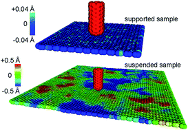
Fig. 3 Dependence of friction force on temperature at various normal loads for a supported sample scanned by a d = 1.2 nm tip (a), schematic representation of the rippling process (b), and typical simulated surface morphology snapshots in supported and suspended samples at 0 nN load and T = 300 K (c). The color ranges in (c) correspond to the atomic out-of-plane positions in the corresponding samples.

In addition to free-standing samples, we studied the dependence of friction on temperature in the case of a 1352-atom sample, in which all atoms were harmonically restrained to their initial positions in the flat phase (left inset of Fig. 1), effectively representing a sample strongly supported by substrate. The results are shown in Fig. 3(a), where we observe image file: c5ra01581b-t3.tif trends similar to the experimental data on graphite28 and in agreement with existing theory.29,30 Simulations of the same sample performed at a lower scan rate of 0.1 m s−1 revealed identical decreasing trends.

It is noteworthy that high simulated scan rates can have a profound effect on the friction's dependence on temperature, such as that in Fig. 2(a) and 3(a). According to the existing theory, the dependence of friction on temperature is ultimately affected by the so-called critical sliding velocity,30 applicable in our case, because the lateral force profile remains periodic (see Section S1 of the ESI). This threshold velocity separates the regimes of stick-slip and continuous sliding along a periodic energy profile, and is equal to image file: c5ra01581b-t4.tif, where f0 is the maximum lateral attempt frequency (a fitting parameter in this case), kB is the Boltzmann constant, a = 0.246 nm is the lattice constant of graphene, and k is the tip-sample lateral stiffness.30 With k ≅ 1.5 N m−1 (from the typical lateral force as a function of the lateral sliding distance) and f0 ≈ 100 GHz, the critical velocity limits for the suspended and supported samples at T = 2 K and 500 K are 2 cm s−1 and 4.2 m s−1, respectively. The value of v0 reaches 1 m s−1 at T = 120 K, which suggests that the simulated scans at 1 m s−1 were performed in the continuous sliding regime at T < 120 K (see ESI). Despite the v0T dependence, theory predicts image file: c5ra01581b-t5.tif for the suspended and the supported samples in the entire simulated temperature range (see ESI). We therefore have an outstanding qualitative difference observed between the free-standing and the supported samples at low normal loads, which cannot be explained within the current theoretical model. The observed difference therefore suggests an applicability limit of the existing theoretical model for the free-standing atomically thin membranes. Importantly, as we show further, lateral scans performed at 0.1 m s−1 yield a friction vs. temperature dependence similar to that shown in Fig. 2(a). We therefore believe that a different, more general mechanism is responsible for the differences observed between the free-standing and supported samples.

We propose that the behavior observed in Fig. 2(a) is a direct effect of the tip interacting with the thermally excited dynamic ripples intrinsic for free-standing atomically thin membranes.17,18 Atomically thin crystals are fundamentally barred from strict two-dimensionality at finite temperatures,17,18,34,36,37 and thermally excited flexural ripples were recently measured with use of scanning tunneling microscopy (STM).38 Such ripples effectively present dynamic random asperities in front of the moving tip. The effect is not present in supported samples, because the ripples are effectively suppressed, allowing only for the high-frequency atomic vibration around the equilibrium sites. As a result of rippling in free-standing samples (as clearly observed in Fig. 2(c)), during lateral scanning, the tip is probing a dynamically corrugated surface, as shown schematically in Fig. 3(b) and also directly visualized from our simulations in Fig. 3(c). It is important to realize that the dynamic rippling effects considered here are separate from (and additional to) the quasistatic wrinkles induced in atomically thin layers by strain, or boundaries,39–41 also structurally expected from considerably thicker polymer layers.42

According to the theory of thermally fluctuating membranes, the ripples' Fourier amplitudes h(q) scale with the membrane temperature T (ref. 17 and 34) as

 
image file: c5ra01581b-t6.tif(1)
where κ is the membrane's bending rigidity. Eqn (1) implies h(q) ∝ 1/q2 and yields the following average:17,34
 
image file: c5ra01581b-t7.tif(2)
where L is the characteristic membrane size. For the membrane dimensions considered here, both theoretically calculated and simulated root-mean-square heights image file: c5ra01581b-t8.tif are non-negligible compared to the 1.42 Å C–C bond length (see ESI), in accord with previous reports on graphene membranes of similar dimensions.17,18,37 Further, the STM measurement yields image file: c5ra01581b-t9.tif for a considerably larger free-standing membrane,38 suggesting a possibly significant effect of ripples in experimental FFM scans. Such rippling magnitudes suggest that free-standing graphene cannot be assumed to be atomically flat during a FFM scan at normal loads sufficiently low not to suppress the rippling process via membrane stretching.

It is straightforward to demonstrate that for a static corrugated surface, according to the Tabor model,43 the friction force F increases with the effective roughness as

 
F = F0(T)(1 + εφ2〉), (3)
where F0 is the friction force on an atomically flat surface subject to thermal activation, ε is a dimensionless coefficient corresponding to the degree of plasticity in the tip-sample interactions, and φ is the tip-asperity effective incidence angle assumed to be small. Regardless of the dynamic nature of the ripples considered here, a similar discussion is possible at least in the qualitative sense due to the overall statistical effect the of ripples' presence, which strongly contributes to the tip-sample energy dissipation during a FFM scan. Note that eqn (3) is qualitatively valid only at normal loads close to zero, as it generally neglects the viscoelastic frictional component from sample indentation, described earlier for higher loads in smaller samples,8 where the rippling process was suppressed and thus conventional frictional mechanisms dominated. Also, the additive form of eqn (3) in this case is unlikely to capture the complete physical picture, because the presence of ripples affects the thermal activation mechanism itself, as discussed below. Nevertheless, a qualitative discussion is possible. Let us consider an additive correction to the conventional thermally activated van der Waals bonding–debonding process (corresponding to the results in Fig. 3(a)) so that total friction takes the form of eqn (3). In this case, ε is a dimensionless parameter depending on the normal load, scan velocity, and possibly boundary conditions (including the boundary dissipative properties), and F0(T) is the thermally activated friction force, which, as we show further, should include the effect of rippling. For a point slider, φ is the angle between the local normal and the 001 direction,43 while for a tip of finite diameter d, image file: c5ra01581b-t10.tif. Substituting the latter expression with use of eqn (2) into eqn (3), we obtain
 
image file: c5ra01581b-t11.tif(4)

Approximating the thermally activated mechanism as F0(T) = F0 K − ΔF(T) (e.g. Fig. 3(a)), the normalized values in Fig. 2 are given by

 
image file: c5ra01581b-t12.tif(5)
with image file: c5ra01581b-t13.tif, describing an effective competition between the product terms. Eqn (5) reduces to the standard thermally activated model for large κ (corresponding effectively to the surfaces of three-dimensional solids). It also suggests a image file: c5ra01581b-t14.tif dependence for b(T) ≪ 1, similar to the results in Fig. 2(a). In addition, within eqn (5) the observation of increasing load-induced gradual return to the conventional behavior can be explained by ripple suppression due to membrane stretching due to external loads and any boundary-induced pre-strain, which affects both κ and b(T). A more subtle point should be made regarding the effect of finite tip size even within the simplified view of eqn (5). A finitely-sized round slider of diameter d, as is often the case for FFM tips, is ripple-selective beyond the 1/d dependence in eqn (5). The ripples with wavelengths below d are not expected to present considerable asperities in front of the tip. Instead, such short ripples will be located under the tip (see Fig. 3(b)), contributing to the thermally activated component F0(T). Therefore, the shortest ripple wavelength capable of introducing a randomly present asperity in front of the tip is d, for dL resulting in a further tip size effect:
 
image file: c5ra01581b-t15.tif(6)
The effect of short ripples under the tip is expected to be significant for the thermally activated mechanism itself, even if we neglect the strong Bragg peaks in the short-wavelength part of the distribution (see ESI). The overall amount of rippling under the tip from eqn (1) is image file: c5ra01581b-t16.tif for T = 300 K, d = 1.2 nm, κ = 2.2 eV27 – an order of magnitude larger than the Debye–Waller factor of graphene,44,45 critical to the thermal activation mechanism. The overall effect of rippling can therefore be summarized as follows: increasing temperature causes the presence of long-wave asperities of increasing height in front of the tip (via the image file: c5ra01581b-t17.tif term), while each asperity becomes more “slippery” via short ripple-enhanced thermal activation (via the (1 − b(T)) term).

The discussion above leads us to an important point: in deriving eqn (6), we utilized eqn (1) from the classical theory of thermally fluctuating membranes, resulting in the linear image file: c5ra01581b-t18.tif scaling of the image file: c5ra01581b-t19.tif term. In reality (at least partially represented by an atomistic model), the height distribution of ripples can strongly depart from the 1/q2 scaling in eqn (1) due to coupling between stretching and bending modes17,18 (also see ESI). Therefore, given the competitive nature of eqn (6), one can expect a far more intricate dependence of the low-load friction on the sample size, and/or local boundary-induced lateral strains via modification of the ripple height distribution, resulting in a significant modification to the entire long-ripple contribution. Of particular importance, the linear scaling with the effective membrane size L may have to be replaced with L(1−η/2) where η is an effective, possibly temperature (and size) dependent fitting parameter described elsewhere,18 especially relevant to membranes considerably larger than those discussed here. Therefore, as stated above, significant changes to both the image file: c5ra01581b-t20.tif and b(T) terms in eqn (6) are contributed to by the ripples in front of and under the tip, respectively (also see section 4 of ESI).

In addition to the discussion above, the effect of tip diameter in eqn (6) for a given 8192-atom sample can be observed in Fig. 4(a), where we compare friction vs. temperature, as obtained with tip diameters of 1.2 nm and 2.2 nm. For the d = 2.2 nm tip, the normalized friction values are lower than those obtained with a d = 1.2 nm tip, consistent with our earlier suggestion that the tip diameter scaled image file: c5ra01581b-t21.tif term in eqn (6) dominates the results in Fig. 2(a). In general, we believe that the effects described here are observable for larger tips, provided that FFM scans are performed on L ≪ d membrane samples due to membrane size scaling. Interestingly, the sensitive dependence of friction on the rippling distribution and the tip size suggests a possibility of externally excited ripples,37,38 as well as strain-induced modification of the rippling patterns for controlling friction in nanoelectromechanical applications, possibly including controlled superlubricity.


image file: c5ra01581b-f4.tif
Fig. 4 Normalized friction vs. temperature for d = 2.2 nm and d = 1.2 nm tips (0 nN load) for the 8192-atom sample (a); normalized friction as a function of temperature for a 5408-atom sample scanned by a d = 1.2 nm tip at various scan rates (b).

Experimental observability of the rippling effects at considerably lower lateral scan rates is important, provided the vast difference between experimental FFM scan rates and those used in MD simulations. We therefore performed additional simulations at considerably lower scan rates of 0.1 m s−1 (simulated for 40 ns) and 0.25 m s−1 (simulated for 20 ns). We selected the 5408-atom sample, which exhibits a image file: c5ra01581b-t22.tif trend during a 1 m s−1 scan. As shown in Fig. 4(b), local image file: c5ra01581b-t23.tif regions are observed at lower scan rates. The changes in monotonicity of F(T) again suggest a strong velocity dependence in the competing terms in eqn (5) and (6). Our results therefore indicate a possibility of observing the effects of thermally induced ripples on friction at lower lateral scanning rates.

Conclusions

Our work demonstrates a unique case of temperature-dependent dynamic roughness observed in suspended graphene as a result of thermally excited flexural waves. In contrast with the existing theory and experimental results for the surfaces of ordinary solids, we demonstrate the possibility of kinetic friction to both increase and decrease with increasing temperature, depending on the tip size, scanning rate, and lateral strain imposed upon the membrane sample. The effects reported are likely be observable experimentally and can occur under low normal loads in other free-standing atomically thin membranes. The sensitive dependence of friction to the flexural ripple patterns suggests control of frictional properties of atomically thin membranes (including imposed superlubricity) via externally excited flexural vibrations, as well as via externally applied lateral strains.

Acknowledgements

The author is grateful to R. J. Cannara, J. P. Killgore, A. F. Kazakov, V. K. Tewary, and K. Kroenlein for useful discussions and comments. This work is a contribution of the National Institute of Standards and Technology, an agency of the US government. Not subject to copyright in the USA.

References

  1. T. Filleter, et al., Friction and Dissipation in Epitaxial Graphene Films, Phys. Rev. Lett., 2009, 102(8), 08610 CrossRef.
  2. D. Berman, A. Erdemir and A. V. Sumant, Few layer graphene to reduce wear and friction on sliding steel surfaces, Carbon, 2013, 54(0), 454–459 CrossRef CAS PubMed.
  3. D. Berman, A. Erdemir and A. V. Sumant, Reduced wear and friction enabled by graphene layers on sliding steel surfaces in dry nitrogen, Carbon, 2013, 59(0), 167–175 CrossRef CAS PubMed.
  4. D. Berman, A. Erdemir and A. V. Sumant, Graphene: a new emerging lubricant, Mater. Today, 2014, 17(1), 31–42 CrossRef CAS PubMed.
  5. D. Berman, et al., Extraordinary Macroscale Wear Resistance of One Atom Thick Graphene Layer, Adv. Funct. Mater., 2014, 6640–6646 CrossRef CAS.
  6. C. Lee, et al., Frictional Characteristics of Atomically Thin Sheets, Science, 2010, 328(5974), 76–80 CrossRef CAS PubMed.
  7. P. Liu and Y. W. Zhang, A theoretical analysis of frictional and defect characteristics of graphene probed by a capped single-walled carbon nanotube, Carbon, 2011, 49(11), 3687–3697 CrossRef CAS PubMed.
  8. A. Smolyanitsky, J. P. Killgore and V. K. Tewary, Effect of elastic deformation on frictional properties of few-layer graphene, Phys. Rev. B: Condens. Matter Mater. Phys., 2012, 85(3), 035412 CrossRef.
  9. Z. Ye, et al., Role of wrinkle height in friction variation with number of graphene layers, J. Appl. Phys., 2012, 112(11), 116102 CrossRef PubMed.
  10. A. Smolyanitsky and J. P. Killgore, Anomalous friction in suspended graphene, Phys. Rev. B: Condens. Matter Mater. Phys., 2012, 86(12), 125432 CrossRef.
  11. Z. Deng, et al., Nanoscale Interfacial Friction and Adhesion on Supported versus Suspended Monolayer and Multilayer Graphene, Langmuir, 2013, 29(1), 235–243 CrossRef CAS PubMed.
  12. Z. Deng, et al., Adhesion-dependent negative friction coefficient on chemically modified graphite at the nanoscale, Nat. Mater., 2012, 11(12), 1032–1037 CAS.
  13. X.-Z. Liu, et al., Nanoscale Adhesive Properties of Graphene: The Effect of Sliding History, Adv. Mater. Interfaces, 2014, 1(2), 1300053 Search PubMed.
  14. A. Smolyanitsky, et al., Effects of surface compliance and relaxation on the frictional properties of lamellar materials, RSC Adv., 2014, 4(51), 26721–26728 RSC.
  15. S. Kwon, et al., Enhanced Nanoscale Friction on Fluorinated Graphene, Nano Lett., 2012, 12(12), 6043–6048 CrossRef CAS PubMed.
  16. Y. Dong, X. Wu and A. Martini, Atomic roughness enhanced friction on hydrogenated graphene, Nanotechnology, 2013, 24(37), 375701 CrossRef PubMed.
  17. A. Fasolino, J. H. Los and M. I. Katsnelson, Intrinsic ripples in graphene, Nat. Mater., 2007, 6(11), 858–861 CrossRef CAS PubMed.
  18. J. H. Los, et al., Scaling properties of flexible membranes from atomistic simulations: application to graphene, Phys. Rev. B: Condens. Matter Mater. Phys., 2009, 80(12), 121405 CrossRef.
  19. L. Lindsay and D. A. Broido, Optimized Tersoff and Brenner empirical potential parameters for lattice dynamics and phonon thermal transport in carbon nanotubes and graphene, Phys. Rev. B: Condens. Matter Mater. Phys., 2010, 81(20), 205441 CrossRef.
  20. S. A. Adelman and J. D. Doll, Generalized Langevin equation approach for atom/solid-surface scattering: general formulation for classical scattering off harmonic solids, J. Chem. Phys., 1976, 64(6), 2375–2388 CrossRef CAS PubMed.
  21. J. E. Jones, On the Determination of Molecular Fields. II. From the Equation of State of a Gas. Proceedings of the Royal Society of London. Series A, Containing Papers of a Mathematical and Physical Character, 1924, vol. 106(738), pp. 463–477 Search PubMed.
  22. R. Zacharia, H. Ulbricht and T. Hertel, Interlayer cohesive energy of graphite from thermal desorption of polyaromatic hydrocarbons, Phys. Rev. B: Condens. Matter Mater. Phys., 2004, 69(15), 155406 CrossRef.
  23. L. Spanu, S. Sorella and G. Galli, Nature and Strength of Interlayer Binding in Graphite, Phys. Rev. Lett., 2009, 103(19), 196401 CrossRef.
  24. M. Hasegawa, K. Nishidate and H. Iyetomi, Energetics of interlayer binding in graphite: the semiempirical approach revisited, Phys. Rev. B: Condens. Matter Mater. Phys., 2007, 76(11), 115424 CrossRef.
  25. S. L. Mayo, B. D. Olafson and W. A. Goddard, DREIDING: a generic force field for molecular simulations, J. Phys. Chem., 1990, 94(26), 8897–8909 CrossRef CAS.
  26. A. Shakouri, T. Y. Ng and R. M. Lin, A new REBO potential based atomistic structural model for graphene sheets, Nanotechnology, 2011, 22(29), 295711 CrossRef CAS PubMed.
  27. A. Smolyanitsky, Molecular dynamics simulation of thermal ripples in graphene with bond-order-informed harmonic constraints, Nanotechnology, 2014, 25(48), 485701 CrossRef PubMed.
  28. X. Zhao, et al., Thermally Activated Friction, Tribol. Lett., 2007, 27(1), 113–117 CrossRef CAS PubMed.
  29. G. A. Tomlinson, A Molecular Theory of Friction. Philosophical Magazine, 1929. vol. 7(46): pp. 905–939 Search PubMed.
  30. E. Riedo, et al., Interaction Potential and Hopping Dynamics Governing Sliding Friction, Phys. Rev. Lett., 2003, 91(8), 084502 CrossRef CAS.
  31. A. Schirmeisen, et al., Temperature dependence of point contact friction on silicon, Appl. Phys. Lett., 2006, 88(12), 123108 CrossRef PubMed.
  32. R. Szoszkiewicz and E. Riedo, Nucleation Time of Nanoscale Water Bridges, Phys. Rev. Lett., 2005, 95(13), 135502 CrossRef.
  33. C. Greiner, et al., Local Nanoscale Heating Modulates Single-Asperity Friction, Nano Lett., 2010, 10(11), 4640–4645 CrossRef CAS PubMed.
  34. Statistical Mechanics of Membranes and Surfaces, ed. D. Nelson, S.Weinberg, and T.Piran, World Scientific: Singapore, 2nd edn, 2004 Search PubMed.
  35. I. Barel, et al., Multibond Dynamics of Nanoscale Friction: The Role of Temperature, Phys. Rev. Lett., 2010, 104(6), 066104 CrossRef.
  36. N. D. Mermin, Crystalline Order in Two Dimensions, Phys. Rev., 1968, 176(1), 250–254 CrossRef.
  37. A. Smolyanitsky and V. K. Tewary, Manipulation of graphene's dynamic ripples by local harmonic out-of-plane excitation, Nanotechnology, 2013, 24(5), 055701 CrossRef CAS PubMed.
  38. P. Xu, et al., Unusual ultra-low-frequency fluctuations in freestanding graphene, Nat. Commun., 2014, 5, 3720 CAS.
  39. J. C. Meyer, et al., The structure of suspended graphene sheets, Nature, 2007, 446(6), 60–63 CrossRef CAS PubMed.
  40. W. Zhu, et al., Structure and electronic transport in graphene wrinkles, Nano Lett., 2012, 12(7), 3431–3436 CrossRef CAS PubMed.
  41. P. Egberts, et al., Frictional Behavior of Atomically Thin Sheets: Hexagonal-Shaped Graphene Islands Grown on Copper by Chemical Vapor Deposition, ACS Nano, 2014, 8(5), 5010–5021 CrossRef CAS PubMed.
  42. B. Gotsmann and U. Dürig, Thermally Activated Nanowear Modes of a Polymer Surface Induced by a Heated Tip, Langmuir, 2004, 20(4), 1495–1500 CrossRef CAS.
  43. I. J. Ford, Roughness effect on friction for multi-asperity contact between surfaces, J. Phys. D: Appl. Phys., 1993, 26(12), 2219 CrossRef.
  44. B. Shevitski, et al., Dark-field transmission electron microscopy and the Debye–Waller factor of graphene, Phys. Rev. B: Condens. Matter Mater. Phys., 2013, 87(4), 045417 CrossRef PubMed.
  45. V. K. Tewary and B. Yang, Singular behavior of the Debye–Waller factor of graphene, Phys. Rev. B: Condens. Matter Mater. Phys., 2009, 79(12), 125416 CrossRef.

Footnote

Electronic supplementary information (ESI) available. See DOI: 10.1039/c5ra01581b

This journal is © The Royal Society of Chemistry 2015
Click here to see how this site uses Cookies. View our privacy policy here.