K. Balakumar and
N. Kalaiselvi*
Electrochemical Power System Division, CSIR-Central ElectroChemical Research Institute, Karaikudi–630 006, India. E-mail: kalaiselvicecri@gmail.com
First published on 31st March 2015
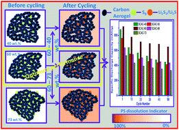
An attempt made to improve sulfur loading in a template-free porous carbon to the extent of 70 wt% has led to two interesting observations being inferred, viz., 60 wt% sulfur loading exhibits superior electrochemical properties in the S@C composite form and an enhanced 73 wt% sulfur loading leads to the formation-cum-stabilisation of sulfur in its monoclinic phase. Carbon aerogel with tunable properties, derived from the catalyst-aided cross linking of resorcinol and formaldehyde, possessing a specific surface area of 1395 m2 g−1 and pore volume of 1.423 cm3 g−1 has been exploited for sulfur loading to form a series of S@C composites. Interestingly, carbon aerogel prepared in the present study offers multifarious advantages such as conducting additive, potential host to accommodate higher concentrations of sulfur and better polysulfide confining matrix. The 60 wt% sulfur loaded carbon aerogel composite exhibits an appreciable specific capacity of 600 mA h g−1 at a C/10 rate up to 100 cycles, 480 mA h g−1 at a 1C and 422 mA h g−1 at a 2C rate. Hence, the capability of carbon aerogel, synthesized through the present study in accommodating higher concentrations of sulfur, effective management of polysulfide shuttle, and provision of favorable electrode–electrolyte interface to facilitate extended cycling possibilities at different current densities has been demonstrated.
16Li + S8 ↔ 8Li2S. |
However, the incredible performance of a lithium–sulfur system is hindered by factors such as the insulating nature of sulfur (5 × 10⁻³⁰ S cm−1 at 25 °C), electrochemically generated solid/soluble reaction products, a shuttling reaction between long and small chain polysulfides, irreversible deposition of Li2S and/or Li2S2, unavoidable volume changes of the cell upon cycling, and the storage performance of sulfur.8–10 So, sulfur should be embedded in an electrically conductive, polysulfide confining matrix that may buffer the volume changes associated with the Li–S system. Towards this objective, engineering of electrodes with required pore size, pore volume and surface area to ensure better utilization of sulfur in the electrochemical cell assembly is the potential approach to qualify lithium–sulfur batteries for practical applications.
Solution mediated infiltration of sulfur into activated mesoporous carbon,10 confinement of sulfur in ordered porous carbon using a melt diffusion strategy with polymer coating,11 infusion of sulfur into hollow carbon to ensure untroubled charge transport even at high rated current and effective trapping of polysulfides,12 hollow carbon fiber host for sulfur guest in a small wall thickness of carbon for beneficial electron and lithium ion movement,13 and superior performance of graphite plane intercalated sulfur in disordered carbon14 are a few examples of carbon-based sulfur electrodes that demonstrate the superiority and suitability of the same for application in Li–S batteries.
In addition to carbon, graphene–sulfur15 and carbon black attached graphene wrapped PEG covered sulfur16 to increase the utility of sulfur are reported in the literature. Graphene with several unique properties,17 despite being considered as a beneficial additive for lithium-ion batteries at high rate applications,18 could not solve the issues of a sulfur cathode15 and it requires specific structures to ensure high utilization of sulfur.16 Further, conducting polymers such as polypyrrole,19 polythiophene,20 poly(3,4-ethylenedioxy-thiophene),21 polyaniline22 and poly(acrylonitrile)23 have also been deployed to chemically and/or physically confine sulfur and polysulfides to alleviate undesired dissolution, apart from enhancing the conductivity to improve the overall performance of Li–S batteries. Similarly, polysulfide adsorbing insulating materials such as SiO2 and Al2O3 are also reported to improve the electrochemical performance of a sulfur cathode in a Li–S system.25,26
Among the existing cathodes, carbon-based sulfur composites are preferred, due to the provision of facile electron channels to sulfur and better polysulfide confinement. Usually, such porous carbon materials for sulfur are obtained by means of template methods, which involve a number of sequences and hence are tedious. On the other hand, the present study deals with the development of carbon aerogel, wherein a porous nature has been achieved by cross-linking during sol–gel condensation, thus excluding porogen elimination. Such an aerogel assumes importance for its ability to tailor the pores and morphology by tuning the synthesis conditions and, accordingly, the impregnation and utilization efficiency of loaded sulfur could also be modified. Herein, acid catalysed cross linkage formation and the deployment of optimized pH27,28 are taken into special consideration to obtain the carbon aerogel with large surface area, desired pore size, distribution of pores, and pore volume. Because it is well known that, while microporous carbon facilitates higher rate performance of a sulfur cathode, the mesoporous carbon enhances lithium transport properties, besides ensuring the confinement of polysulfides and sulfide ions obtained from the electrochemical reaction. In other words, microporous carbon suffers from lower sulfur loading and the mesoporous nature enhances the rate capability behavior of a sulfur cathode. Further, it is well known that the amount of loaded and utilized sulfur in a cathode determines the volumetric energy density of a cell.28
Based on these grounds, mesoporous carbon aerogel from an acid-mediated resorcinol–formaldehyde (RF) sol–gel reaction, obtained at a pH of below 6, was prepared with a specific surface of 1395 m2 g−1, which was found to be bestowed with the possibility of accommodating higher amounts of sulfur. The currently prepared carbon aerogel, containing 60 wt% sulfur, supersedes the previous work with limited volumetric energy density.29 The appreciable performance of S@C composites containing different concentrations of sulfur loading was also demonstrated. Higher sulfur loading and the maintenance of appreciable capacity of 600 mA h g−1 upon extended cycling (up to 100 cycles) are twin advantages achieved from the currently developed sulfur cathode, impregnated in a carbon aerogel, consisting of mesoporous carbon in larger proportions along with the co-existence of micropores.
![]() | ||
Fig. 1 XRD pattern of sulfur, carbon aerogel, 40 wt%(SCAC-40), 50 wt%(SCAC-50), 60 wt%(SCAC-60), 66 wt%(SCAC-66) and 73 wt%(SCAC-73) sulfur loaded carbon aerogel. |
Thermogravimetry analysis was performed under nitrogen atmosphere and up to 500 °C with a heating rate of 10 °C min−1. From this measurement, −dW/dT versus temperature was plotted and is displayed in Fig. 2 along with the variation in weight loss as a function of temperature. The amount of sulfur in CA was calculated based on weight loss of the composite at 500 °C and these values were used to formulate and denote the samples with a general representation SCAC-X, where X stands for the sulfur content (e.g. SCAC-40 contains 40 wt% of sulfur). In other words, the adsorption ability of carbon aerogel for various amounts of sulfur loading can be evaluated using TGA analysis. Since it is based on the evaporation of sulfur from the pores of carbon aerogel, the region occupied by the −dW/dT versus temperature curve indicates the adsorption ability of CA vs. amount of sulfur loading.10 From Fig. 2, it is evident that major weight loss occurs at 240 °C for SCAC-60 which occupies the highest region than other SCAC samples, thus implying the need for more thermal energy to remove sulfur from CA. Hence, the relatively superior thermal stability of SCAC-60 composite may be understood.
Raman microscopy is a non-destructive technique, which is a powerful tool to analyse the nature of carbon materials such as graphitic or amorphous states. It is quite reasonable to study the change in the structure of carbon in the carbon aerogel, especially upon sulfur loading and its interaction using this technique. In Fig. 3(a), the intense in-plane stretching vibration of pairs of sp2 carbon, corresponding to E2g symmetry (G band) that appears at 1597 cm−1, defect or graphite stimulated six fold aromatic ring breathing vibration, corresponding to A1g (D band) at 1320 cm−1 along with the overtone of in-plane phonon related 2D peak centered at ∼2581 cm−1, and D + G peak at ∼2896 cm−1 are evident. The presence of such a combination of D, G, 2D and D + G peaks confirms the presence of nano and polycrystalline graphitic carbon tied with amorphous carbon in the currently prepared carbon aerogel.31 The crystallite size La32 can be calculated from the intensity ratio of D and G bands, which is about 39.45 nm.
![]() | ||
Fig. 3 Raman spectrum of (a) carbon aerogel, (b) sulfur–carbon aerogel composites and (c) 50 wt% sulfur loaded and sulfur removed carbon aerogel composites. |
Raman spectra of chosen combination of sulfur–carbon aerogel composites are shown in Fig. 3(b). It is quite interesting to note that the ID/IG ratio increases upon sulfur loading (Table 1), as evident from the increasing intensity of a broader D band that surpasses the narrow G band. However, the ID/IG value increases from SCAC-40 to SCAC-60 and decreases thereafter with the increasing concentration of sulfur (such as SCAC-66 and SCAC-73). Hence, it is understood that the amount of sulfur dispersed into the carbon aerogel could be quantified using the calculated ID/IG values i.e., with the increasing loading of sulfur, disorder also increases in the carbon aerogel with an exception of SCAC-66 and SCAC-73. However, the Raman spectrum recorded for SCAC-73 is entirely different from the rest of the composites, as it contains the co-existing Raman signatory peaks due to sulphur and CA. This in turn is an indication that a small portion of sulfur remains on the surface of the CA, besides filling the pores of carbon aerogel. From this observation, it is understood that a concentration of 73 wt% sulfur is slightly excess than the maximum possible concentration that could be accommodated in the pores of the CA, thus helping us to conclude that nearly 70 wt% sulfur uptake is possible with the currently prepared CA that blocks the surface of CA partially. This is in agreement with the XRD results, wherein peaks corresponding to CA are not visible in SCAC-73. The effect of sulfur loading in changing the graphitic nature of CA towards an amorphous form is well understood from the comparison of Raman spectra in Fig. 3(c) of SCAC-50 and the corresponding sulfur removed CA (sulfur was removed by heating SCAC-50 in N2 atmosphere for 2 h at 500 °C and the temperature was fixed based on a TGA study). Such a typical and random analysis of Raman spectral behavior confirms the fact that the added sulfur plays a vital role in gradually changing the slightly pronounced amorphous nature of CA. However, the co-existence of graphitic and amorphous nature of CA is always beneficial for sulfur cathodes in terms of electrical network (otherwise known as carbon wiring) and buffers the volume changes. Hence, the Raman study offers an indication that SCAC-60 may give rise to better electrochemical behavior compared with the rest of the composites, and the SCAC-73 composite may not be suitable for application in Li–S batteries (as inferred from XRD also).
D-Raman shift (cm−1) | G-Raman shift (cm−1) | ID | IG | ID/IG | La (nm) | |
---|---|---|---|---|---|---|
CA | 1320.23 | 1597.91 | 510.96 | 526.40 | 0.97 | 39.45 |
SCAC-40 | 1315.58 | 1597.03 | 333.07 | 302.00 | 1.10 | 34.72 |
SCAC-50 | 1319.30 | 1601.46 | 312.45 | 266.58 | 1.17 | 32.67 |
SCAC-60 | 1321.16 | 1597.91 | 464.12 | 386.24 | 1.20 | 31.86 |
SCAC-66 | 1316.51 | 1597.03 | 453.23 | 388.39 | 1.17 | 32.81 |
SCAC-73 | 1325.85 | 1604.12 | 298.73 | 271.16 | 1.10 | 34.76 |
Nitrogen adsorption–desorption isotherms were recorded at 77 K for CA, SCAC-50 and SCAC-60 in a range of relative pressure P/P0 from 0.1 to 1.0. The isotherm curve in Fig. 4(a) corresponding to carbon aerogel exhibits a type-IV isotherm with H1 hysteresis33 and the capillary condensation is centered at a relative pressure of 0.82. Similar behavior was noticed for SCAC-50 and SCAC-60, except the decrease in adsorbed volume observed as a function of increasing sulfur content. The decrease in adsorbed volume is evidence that elemental sulfur occupies the available pores of CA. BET surface area and related parameters of CA were calculated and the values of surface area, maximum pore width and pore volume were tabulated (Table 2). Surprisingly, higher specific surface area and pore volume of 1395 m2 g−1 and 1.423 cm3 g−1 were calculated for CA, corresponding to a maximum width of 9.676 nm of carbon aerogel, deduced from the pore distribution curve (Fig. 4(b)). It is a quite reasonable incentive to use such a carbon aerogel with an appreciable high surface area to impregnate sulfur and to exploit the same as a potential cathode for Li–S system. Such an idea may be validated based on the highest theoretical loading possibility of sulfur, which has been calculated to be 74.66% in CA. As expected, the pore volume and surface area of CA decrease with increasing sulfur loading, thus substantiating the assumption that the probable location of sulfur is in the pores. For 50 wt% loading, the specific pore volume and specific surface area are reduced to 0.707 cm3 g−1 and 331.046 m2 g−1 and for 60 wt% loading, it further reduces to 0.237 cm3 g−1 and 16.830 m2 g−1 respectively. These values are consistent with the previous inference related to the location of sulfur in CA host within the pores. As a result, enhanced electrical conductivity and better buffering to allow volume expansion during cycling performance are expected with the currently designed sulfur impregnated carbon aerogel.
![]() | ||
Fig. 4 (a) Nitrogen adsorption–desorption isotherm of carbon aerogel and select sulfur–carbon aerogel composites and (b) corresponding pore volume distribution. |
Sample | Pore width (nm) | Specific surface area (m2 g−1) | Specific pore volume (cm3 g−1) |
---|---|---|---|
CA | 9.68 | 1395.62 | 1.42 |
SCAC-50 | 9.63 | 331.05 | 0.71 |
SCAC-60 | 9.60 | 16.83 | 0.24 |
FESEM images of carbon aerogel at low and high magnification are shown in Fig. 5(a) and (b). It is obvious from the figure that the particles are properly interconnected with each other to enable three dimensional electron conduction and the particle size is found to be less than 100 nm. The available pores of the interconnected particles render transport paths to sulfur, especially during melt diffusion, and aided the confinement of sulfur in the porous structure. The TEM image in Fig. 5(c) also shows the interconnected network of CA, wherein region that appears as grey corresponds to the overlap at the edges. However, three or more particles also overlap at the corners and give rise to slightly dark regions, wherein the increased thickness is responsible for the observed darkness. Further, the amorphous nature of the carbon aerogel is understood from the corresponding SAED pattern appended as an inset of Fig. 5(c). In contrast to Fig. 5(c), the HRTEM image of SCAC-60 in Fig. 5(d) contains periodically varying grey and black colour patterns. No overlap of two or more particles in the black area is obvious; hence the black colour region is believed to be due to the presence of impregnated sulfur while the grey region corresponds to that of carbon aerogel. The appearance of a periodic pattern of black and grey areas is due to homogeneous distribution of embedded sulfur in the pores of carbon aerogel, thus evidencing the effective and uniform confinement of sulfur in CA. The corresponding SAED pattern in the inset of Fig. 5(d) confirms the amorphous nature of sulfur impregnated in the carbon aerogel and the same has been substantiated by the XRD results of S@C composites. TEM lattice fringes with a spacing of 0.365 nm (Fig. 5(e)) coincide with the d-spacing in XRD pattern of CA (d(002) = 0.370 nm), thus validating the correlation of TEM-based results with those of XRD. The discontinued lattice fringe patterns observed throughout the TEM image confirms the co-existence of disordered and graphitic nature of CA, which coincides with the results of Raman studies. The energy dispersive X-ray spectrum of SCAC-60 (Fig. 5(f)) shows pronounced peaks for carbon and sulfur and a negligibly small signature for oxygen, thus confirming the elemental composition and stoichiometry of the title cathode with an unavoidable association of trace amount of oxygen (which is not unusual).
In order to confirm the uniform distribution of sulfur in the carbon aerogel, elemental mapping was done by scanning transmission electron spectroscopy (STEM) for the SCAC-60 sample. The area selected for mapping is shown in Fig. 6(a). STEM mapping suggests that sulfur is uniformly distributed in the carbon aerogel and the cumulative mapping results in Fig. 6(d) further ensure the intimate contact of sulfur with the carbon aerogel.
![]() | ||
Fig. 6 (a) Selected area of SCAC-60 composite subjected to elemental mapping, (b) carbon, (c) sulfur, and (d) cumulative elemental mapping image. |
The elements present and the corresponding oxidation state of loaded sulfur in CA can be identified using XPS analysis, which in turn could be used to substantiate the observations made from Raman studies. Fig. 7(a) shows survey spectra of CA and SCAC-60 and the individual scans of identified peaks are shown in Fig. 7(b)–(d). Carbon and elemental oxygen are identified in CA and carbon, sulfur and oxygen are present in SCAC-60 as per Fig. 7(a). The oxygen found in the XPS analysis may be an adsorbed atmospheric oxygen in CA. The peak appeared at 284.14 and 284.17 eV for CA and SCAC-60 in Fig. 7(b) reveals that the binding energy of the 1s electron of the C–C bond34 in carbon aerogel, corresponding to the full width at half maximum (FWHM) of CA, is 1.43 eV while it is 1.73 eV for SCAC-60. The sulfur 2s peak appeared at 222.80 eV (Fig. 7(c)) and the 2p peaks of sulfur contain more information about the bonding nature of sulfur in carbon aerogel. As presented in Fig. 7(d), the 2p raw spectrum of sulfur can be deconvoluted into four component peaks. The peak at 165.50 eV corresponds to 2p1/2 spin–orbital coupling of 2p electrons and the other peak (2p3/2 – I, 2p3/2 – II and 2p3/2 – III) values at 165.0, 164.30 and 163.80 eV correspond to the presence of SO, 2p3/2 spin–orbital coupling and C–S bond respectively.35,36 Hence, it is confirmed from XPS analysis that some of the sulfur atoms are chemically bonded to the carbon aerogel.
![]() | ||
Fig. 7 (a) Survey spectra, (b) 1s carbon spectra of CA and SCAC-60, and (c) and (d) correspond to 2s and 2p spectra containing fitted photoelectron lines of sulfur in SCAC-60 respectively. |
Cyclic voltammetry behavior of 50 (Fig. 8(a)), 60 (Fig. 8(b)) and 66 (Fig. 8(c)) wt% sulfur loaded CA cathodes shows typical and characteristic peaks of sulfur with a slight difference between initial and progressive CV cycles. Two sharp and distinguishable cathodic peaks are observed, which evidence the disproportional electrochemical reduction of elemental sulfur into higher order polysulfides and their subsequent cathode reduction to Li2S/Li2S2 upon extended cathodic potential. The first reduction peak appears at a potential of 2.35, 2.35 and 2.33 V corresponding to SCAC-50, 60, 66 cathodes during the initial cycle and the same is shifted respectively to 2.36, 2.35 and 2.34 V upon progressive cycling (10th CV cycle). The shift in potential upon progressive cycling is found to be admissibly small for SCAC-50 and SCAC-60 cathodes, while the difference in SCAC-66 cathode is a little significant. The utilization of sulfur is found to be higher only upon progressive cycling with a special reference to the SCAC-66 cathode, which is an indication that the initial volume expansion of sulfur in carbon aerogel hampers the complete utilization of active material. The second reduction peak potential of SCAC-(50, 60, and 66) cathodes appears at 2.06, 2.07 and 2.07 V and 2.06, 2.06 and 2.06 V corresponding to the 2nd and 10th cycle respectively. No obvious change in peak potential was noticed for any of the three chosen concentrations of sulfur. However, the peak current value was found to be reduced upon extended cycling, with an exception of the SCAC-60 cathode. In other words, more surface area of SCAC-50 cathode active material that gets exposed to the electrolyte available in unfilled pores enhances the dissolution of active material.37
![]() | ||
Fig. 8 Second and tenth CV cycle behavior of (a) SCAC-50, (b) SCAC-60, and (c) SCAC-66 composite cathode recorded at a scan rate of 0.1 mV s−1. |
A subsequent anodic scan exhibits one broader peak for single step conversion of Li2S2/Li2S into Li2S8/S8. But the CV peak pattern pertinent to the initial and extended cycles is entirely different. Moving from SCAC-50 to 66, the anodic peaks shift towards the cathodic direction and SCAC-50 shows exact confinement of 10th cycle with that of the 2nd cycle, except for the reduced overall current that slightly shifts the peak current position at 2.38 V. On the other hand, the SCAC-60 cathode shows a small shift in the peak position with almost negligible change in peak current. The appearance of a pronounced and well distinguished peak at 2.38 V also appears for the SCAC-66 cathode, which is not as significant as that of SCAC-60. The appearance of an additional anodic peak at 2.38 V, observed during extended cycling, is more pronounced in the SCAC-60 cathode, compared with that of SCAC-66 cathode. Such an appearance of an additional peak arises when sulfur forms an intimate contact with the carbon aerogel.11 So, an overall improved performance has been observed for the SCAC-60 cathode due to the availability of a desired quantity of unfilled pores to buffer the volume expansion. Thermal distribution of sulfur in the CA scaffold is electrochemically redistributed, which reduces the polarization in oxidation peaks. The background current of the CV curve shows the absence of unwanted red-ox reactions in the system, which is noteworthy.
The overall cycling performance observed in CV may be best understood and correlated using the following equations.
2Li + S ↔ Li2S (overall reaction) | (1) |
2Li + S8 ↔ Li2S8 | (2) |
2Li + Li2S8 ↔ 2Li2S4 | (3) |
2Li + Li2S4 ↔ 2Li2S2 (insoluble) | (4) |
2Li + Li2S2 ↔ 2Li2S (insoluble) | (5) |
In short, reactions (2) and (3) correspond to the first plateau and the last two reactions to the second plateau.38
Electrochemical performance of different concentrations of sulfur loaded CA cathodes was evaluated using galvanostatic charge–discharge studies performed at C/10 rate (C = 1675 mA gsulfur−1) (Fig. 9) and the current calculation was made, based on the weight of sulfur in the electrode. Typical two plateau electrochemical reduction behavior of voltage profile was exhibited by all the SCAC-X electrodes (Fig. 9(a)), thus evidencing the involvement of the same reduction mechanism in all the chosen cathode formulations. Reduction begins from OCV, which ranges from 2.44 to 2.30 V and exhibits the presence of first and second reduction plateaus, found to present closer to each other. This is an indication that more sulfur is physically adsorbed (free S8).24 A significant reduction of lower order polysulphides in the potential range below 2.1 V was observed for SCAC-40 and 50 cathodes, due to the dissolution of higher amounts of sulfur in the electrolyte. Single plateau oxidation occurs during the initial charging of all the cathodes. However, reasons such as higher electrolyte contact area on lower loading and the non-availability of sufficient pores to buffer volume changes on more loading of sulfur are believed to be the reasons for the appearance of a second oxidation plateau that was observed for all the cathodes, with an exception of 60 wt% loading (in 50th cycle). Further, the length of the second plateau corresponds to 32–37% of the total charging capacity of the individual cathodes, which is an indication that the resultant capacity arises from the reduction of higher order polysulfide to elemental sulfur. In other words, dissolved polysulfides (liquid state) are converted into solid sulfur, which gets accumulated on the surface of carbon rather than accommodating the pores of CA. The lesser polarization behavior exhibited by the SCAC-60 composite cathode substantiates the recommendation of the same as the optimum composition of SCAC-X cathode, suitable for Li–S system. Further, absence of a second plateau observed with the SCAC-60 cathode is evidence that the loaded sulfur has occupied the available pores of CA and no undesirable accumulation of sulfur could be seen on the surface of CA to reduce the effective utilization of sulfur. As a result, the SCAC-60 cathode with negligible polarization change was concluded as the better performing cathode through the present study.
Cycleability studies presented in Fig. 9(b) display initial discharge capacity values of 879, 763, 918, 636 and 533 mA h g−1 with respect to SCAC-X cathodes where X = 40, 50, 60, 66 and 73 respectively. Among the chosen cathodes, the lowest capacity was observed for SCAC-66 and 73 cathodes. Invariably, the capacity becomes stabilized after 10 cycles and the capacity of SCAC-X (X-40, 50, 60, 66, and 73) cathodes after 50 cycles was found to be 450, 413, 649, 435 and 335 mA h g−1, which is about 51, 54, 71, 68, and 63% of the respective initial capacity value. An appreciable and higher capacity value of 649 mA h g−1 with a better retention behavior was shown by the SCAC-60 cathode, as evident from Fig. 9(c). Based on these observations, the SCAC-60 cathode was subjected further to extended cyclability, high rate performance and rate capability analyses.
Extended cyclability of the SCAC-60 cathode (in Fig. 9(d)) at C/10 rate shows a nominal capacity of 600 mA h g−1 after 100 cycles with an acceptable degradation of 0.37% per cycle. At the 100th cycle, it exhibits a capacity of 600 mA h g−1, which is 87% of 30th cycle and 93% of 50th cycle capacity. Similarly, the coulombic efficiency is found to be 90–95% during the first 10 cycles and increased subsequently to 97% upon extended cycling, due to improved stability.
Experimentally observed and fitted impedance spectra of the as-fabricated cell containing the SCAC-60 cathode, and the cell after completing 1 and 100 cycles are shown in Fig. 10 with an inset containing the corresponding equivalent circuit model. Closer resemblance of observed and calculated values is evident from the figure (Fig. 10). The fitted equivalent circuit contains various circuit elements such as Re, Qs//Rs, Qct//Rct and ZW. Here, Re is the electrolyte resistance, Rs is the surface resistance of lithium and SCAC-60 electrode, Rct is the charge transfer resistance, Qs and Qct are the constant phase elements, and ZW is the Warburg impedance.39 From Table 3, the smaller Re value of 1.68 Ω that was observed before cycling exhibits a small variation in electrolyte resistance even after completing 100 cycles. This observation indicates that cycling didn't alter the Re of the cell very much and the small changes observed with respect to the Re of the cell before and after cycling is believed to be due to the small amount of dissolution of loosely bound sulfur at CA. The depressed semicircle at a higher-middle frequency range relates to the Rct value of the cell and it shows 50.86 Ω before cycling, which is found to decrease to the extent of 23.27 and 33.25 Ω after the 1st and 100th cycle respectively. As discussed with CV, the decrease in the charge transfer resistance after cycling is most likely due to the fact that sulfur gets rearranged in the pores and facilitates easy access to both electron and lithium ions. The slight increase in the charge transfer resistance indicates the superior conductive and buffering nature of CA to improve the electrochemical performance of sulfur. The observed inclined line in the lower frequency region corresponds to the diffusion kinetics of electrode, which also follows the same trend for both the 1st and 100th cycle. Hence, the lowest charge transfer resistance of the cell and the same trend observed in the lower frequency region are due to the electrochemically favorable interface properties of CA with the electrolyte.
![]() | ||
Fig. 10 Experimental and fitted Impedance spectra of the as fabricated cell containing the SCAC-60 cathode and the cell after completing 1 and 100 cycles (inset – corresponding equivalent circuit). |
State | Re (Ω) | Rct (Ω) |
---|---|---|
Before cycling | 1.68 | 50.86 |
After 1st cycling | 2.93 | 23.27 |
After 100th cycling | 5.61 | 33.25 |
The role of CA as a conductive matrix to improve the performance of sulfur, formation of Li2S, and the related polysulfide retention in the SCAC-60 cathode was investigated under a high rated current of 1C, which is shown in Fig. 11(a). It demonstrates an initial capacity of 632 mA h g−1 with a coulombic efficiency of 96% and retention of 480 mA h g−1 at the 50th cycle, which is about 76% of initial capacity and 86% of 25th cycle capacity with a coulombic efficiency of 92%. This reveals the advantage of the CA skeleton in improving the electrochemical behavior of sulfur even at high current rates and it emphasizes the polysulfide confinement at 1C rate. Hence, CA prepared in the current study offers multifarious benefits such as a conducting additive, a potential host for higher sulfur loading, and a better polysulfide confining matrix, which is superior to the S@C composite, wherein carbon only acts as a conducting additive.40
The voltage profile of the SCAC-60 cathode under the influence of different current rates, viz., C/7, C/5, C/2, 1C and 2C has been displayed in Fig. 11(b). While the polarization calculated against 50% of the individual capacity is small (155 mV) and similar for C/7 and C/5 rates, it increases slightly (320 mV) for a 2C rate. Such smaller polarization changes demonstrate the intimate contact of the sulfur with CA. However, part of the discharge capacity at 2C is limited by lower cut-off voltage, which is unavoidable. Even though the SCAC-60 cathode provides a significant capacity of 422 mA h g−1 under the influence of a 2C rate, the capacity limiting region in the discharge curve can be identified by evaluating the contribution of each region to the total capacity and the corresponding plot is given in Fig. 11(c). Contribution of the first region on the discharge curve (corresponds to conversion of S8 to Li2S6) to the total capacity is 33, 36, 39, 44 and 52% for C/7, C/5, C/2, 1C and 2C rates respectively and the capacity retentions of this region with respect to the C/7 rate are 95, 92, 84, and 78% for C/5, C/2, 1C and 2C rates respectively. Capacity is mostly limited by the slow reduction kinetics of the second region.41 Rate capability of the SCAC-60 cathode was evaluated under the C/7 rate for first five cycles and subsequently at C/5, C/2, 1C, 2C rates for every other six cycles. Finally, the cell at the 2C rate was brought back to the C/7 discharge condition in order to understand the capacity retention behavior. From the rate capability study in Fig. 11(d), capacity values of 882, 782, 667, 547, 422 were observed corresponding to C/7, C/5, C/2, 1C and 2C rates and finally the capacity was resumed to 698 mA h g−1 for a rate of C/7. The three dimensional interconnected network of carbon aerogel with an ability to occupy ∼70 wt% sulfur shows a reversible capacity of 422 mA h g−1 at the 2C rate up to six cycles and exhibits 698 mA h g−1 of capacity when the current is switched back to the C/7 rate for 60 wt% sulfur loading.
The capacity obtained through the currently prepared sulfur–carbon aerogel composites is appreciable and superior to many other recent works. Y. Zhang et al.,42 reported that a nano-sulfur/polypyrrole/graphene composite with a loading of 52 wt% exhibits a discharge capacity of 324.7 mA h g−1 at the 50th cycle for a 1C rate, which is 150 mA h g−1 lesser than this work and M. Agrawal et al.,43 reported that porous carbon obtained through the template method shows a discharge capacity of 400 mA h g−1 at the 50th cycle for a C/10 rate, which is 200 mA h g−1 lesser than the current work, especially with respect to the 100th cycle.
This journal is © The Royal Society of Chemistry 2015 |