Micro structure fabrication with a simplified hot embossing method

Yong Heab, WenBin Wuab, Ting Zhangab and JianZhong Fu*ab
aThe State Key Lab of Fluid Power Transmission and Control, College of Mechanical Engineering, Zhejiang University, Hangzhou 310027, China. E-mail: yongqin@zju.edu.cn; fjz@zju.edu.cn
bKey Laboratory of 3D Printing Process and Equipment of Zhejiang Province, College of Mechanical Engineering, Zhejiang University, Hangzhou 310027, China

Received 24th January 2015 , Accepted 23rd April 2015

First published on 23rd April 2015


Abstract

A facile hot embossing method—low pressure hot embossing (LPHE)—is reported in this paper. Compared with large and expensive hot embossing machines, just an oven is used for heating with a compact self-designed loading device inside to apply pressure. Due to the small loading device, only a low embossing pressure can be applied. Micro linear arrays were successfully fabricated with this method and the embossing process was systemically investigated. Orthogonal arrays were used to analyze the hot embossing behavior under a low embossing pressure. As LPHE is easy to realize at a cheap price, it is very helpful for researchers interested in fabricating micro structures such as micro fluidic chips used in prototype experiments.

1 Introduction

Hot embossing is a technique of imprinting micro/nano structures on a substrate with a master mold. In recent years, as a typical micro/nano fabrication method, hot embossing has been widely used in many areas, such as micro-fluidic devices,1,2 bioMEMS,3,4 micro-optics5,6 and other applications due to its numerous advantages such as low cost, high efficiency, and parallel operation. This technology has also been widely used in the industrial production of compact discs (CD), digital versatile discs (DVD), the light guide plate of liquid crystal displays, and other products. Over the past few years, hot embossing technology has attracted much research interest and has seen rapid development.7 Several studies have previously investigated the hot embossing method related to the modeling of polymer flow,8–10 optimization of processes,11–15 improvement of apparatus,16–19 and design of novel applications.20–22

With current technology, according to the configuration of the molding tools, three types of hot embossing machines have been reported: plate-to-plate (P2P), roll-to-plate (R2P), and roll-to-roll (R2R).7 Many assistant methods, such as gas pressure,16 rubber pad,17 and ultrasonic vibration18 have also been developed to improve replication quality. However, most of these machines are focused on mass production, are designed for industrial use, and are very expensive. Special clean rooms and staff are needed to operate these hot embossing machines, which makes it difficult to own a single machine at a common lab.

In our previous work,10–13 we developed a hot embossing machine and designed a demolding device to improve imprinting quality. Although we designed and manufactured this machine by ourselves, it still cost %40[thin space (1/6-em)]000. We realize that in many situations, researchers may only need few hot embossing products just for prototyping experiments. Until now, there has been a lack of a facile hot embossing method to rapidly and quickly imprint in low cost. The gas such as CO2 was used in the hot embossing to acquire a uniform imprint pressure.23,24 With this process, the imprint pressure can also be reduce, however this gas-assisted hot embossing device is still complicated and expensive and cannot be seen as a lightweight device. In this paper, we report such a facile method—low pressure hot embossing (LPHE)—to simplify the hot embossing process. We designed a compact loading device and put it into a vacuum oven to create a simple hot embossing machine. We demonstrate here that this method can successfully hot emboss micro structures. Due to its simplicity and low-cost design, almost every lab can do research on hot embossing using our LPHE method.

The paper is organized as follows. Section 2 introduces the design of pressure device and the simplified process of hot embossing. In Section 3, a demonstration of the method is presented using micro grating structures that were hot embossed. Orthogonal tests were used to evaluate the influence of process parameters, followed by a conclusions about the proposed method in Section 4.

2 Materials and methods

2.1 Loading device

A typical hot embossing process can be divided into vacuumizing, embossing, cooling, and demolding steps. A hot embossing machine must be able to heat, apply pressure, and vacuumize at some time. On the other hand, a facile hot embossing device that almost every common lab can utilize must meet the requirements of low cost, easy operation, and compact size. To reach these goals, we utilize a vacuum oven, a common lab device, to vacuumize and heat in this novel hot embossing process. As vacuum is not needed at some low surface quality required applications of hot embossing, a conventional oven can also be used. A compact loading device, which can be put into a vacuum oven, then applies pressure.

When designing the mechanical structure of the compact loading device, the following factors were taken into consideration.

(1) The size of the entire apparatus should be small enough to fit with the small size of the small room of an oven.

(2) During the loading process, the entire loading device will be placed in the vacuum oven. High embossing temperatures will damage electrical components, which means that the device should be composed of only mechanical components.

(3) Without an electrical control system, the apparatus should contain a function to maintain the pressure while the mold is pushed down.

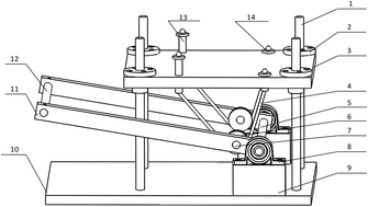
As shown in Fig. 1, the framework of this loading device is made of four guiding columns, a pressure plate, and a bottom plate. The pressure plate and guiding columns are jointed together with a linear bearing to ensure the orientation and linear motion of the pressure plate. This forms a lever system between the pressure plate and the bearing bar by assembling the wire rope, supporting pole, groove wheel, pin, bearing block, and connecting rods. The supporting shoe and the bottom plate are connected by foundation bolts in the annular groove on the lower surface of the bottom plate. In this way, the position of the lever system can be adjusted by changing the supporting shoe's position in the annular groove. The adjustable bolt adjusts the length of wire rope on both sides to keep them equal.


image file: c5ra01410g-f1.tif
Fig. 1 The structure of pressure device. (1) Guiding column; (2) linear bearing; (3) pressure plate; (4) wire rope; (5) supporting pole; (6) groove wheel; (7) pin; (8) bearing block; (9) supporting shoe; (10) bottom plate; (11) connecting rods; (12) bearing bar; (13) adjustable bolt; (14) fixing bolts.

2.2 Simplified hot embossing process

The simplified hot embossing device is shown in Fig. 2. The entire loading process can be divided into four steps as shown in Fig. 3 as follows:
image file: c5ra01410g-f2.tif
Fig. 2 Simplified hot embossing device.

image file: c5ra01410g-f3.tif
Fig. 3 Loading process: (a) construction of the loading system. (b) Applying pressure. (c) Pressure holding process. (d) Pressure releasing process.
(a) Setting up loading system. As shown in Fig. 3a, the first step is to place the up mold, mold and substrate, and base mold onto the bottom plate at the center of the pin (cross shown in Fig. 2a). The up mold, mold and substrate, and base mold should be aligned.
(b) Applying pressure. As shown in Fig. 3b, by hanging weights in the center of the bearing bar, the pressure plate and the mold will have close contact. The pressure plate will generate specific pressure to the mold via the lever system. According to the size of the lever system, magnification of the pressure is 10 times, which means that the pressure on the mold is the sum of 10 times the weight and the pressure plate's weight.
(c) Heating and vacuumizing. The loading device is placed into the vacuum oven then heated to embossing temperature and vacuumize.
(d) Holding pressure. As the polymer substrate softens, the mold will press into the substrate under embossing pressure. The combinations of the linear bearing and the guide column, the groove wheel and the wire pole, and the supporting pole and the bearing block will cause a follow-up movement of the pressure plate to hold the pressure. The direction of the pressure can be ensured to be vertically downward, as shown in Fig. 3c.
(e) Demolding. After the embossing time finishes, the vacuum is released and temperature is decreased. While the substrate is cooling down for mold releasing, pressure can be released by removing the weights and lifting the pressure plate. The pressure releasing process is finished when the mold and the substrate are removed from the bottom plate, as shown in Fig. 3d.

2.3 Micro linear arrays embossing

A vacuum oven (model DZ-1BC) was purchased from Tianjin TaiSiTe Instrument Inc. PMMA plates (1 mm thickness) were purchased from Spolytech Co., Ltd (Korea) and were cut into round samples with a diameter of 60 mm. Molds were fabricated by micro machining on the aluminum sheet; the structure is shown in Fig. 4. Sizes of the mold are listed in Table 1.
image file: c5ra01410g-f4.tif
Fig. 4 The structure of the embossing mold.
Table 1 Mold sizes
No. Width, W/μm Height, H/μm Period, P/μm
1 300 200 1000
2 400 300 600
3 500 300 1000
4 600 1200 1000


Conductive polymer (CP) liquid, poly(3,4-ethylenedioxythiophene):poly(styrenesulfonate), PEDOT:PSS was purchased from Agfa-Gevaert Group (Belgium). The polymer substrate was PMMA, from Spolytech Co., Ltd. The process parameters used for the optimization results of the orthogonal array were embossing temperature T = 150 °C, imprint pressure F = 300 N, and the width of the mold W = 400 μm. The electrical resistance of the micro CP microarray was measured with four point probe technique.25 The micro channel section is characterized by Scanning electron microscopy (SEM) and the CP linear arrays after hot embossing are recorded by a Keyence digital microscope (SRT6200).

2.4 Orthogonal array experiments

Micro linear arrays are typical micro structures that are widely used in light guide plates.26,27 The microstructures of linear arrays have high aspect ratio and high density. Defects can be easily observed after hot embossing if the process parameters are not properly selected or if the hot embossing machine malfunctions. In this paper, linear arrays were used to verify the effectiveness of LPHE.

This orthogonal experimental design is also called the Taguchi method, which is a powerful way to investigate how different parameters affect the mean and variance of a process performance characteristic that defines how well the process is functioning.28 There are four parameters that mainly produce effects on the imprint quality: embossing temperature T, embossing time t, embossing pressure F, and the size of the mold. T, t, F, and W were chosen as the four factors of orthogonal array and a L9(34) orthogonal array was used to investigate the relationship between the parameters and the imprint quality. The level values of T were 140 °C, 150 °C, and 160 °C. The level values of t were 10 min, 20 min, and 30 min. The level values of F were 100 N, 200 N, and 300 N, and the level values of W were 400 μm, 500 μm, and 600 μm, as shown in Table 2. Replication fidelity was used as the index of imprint quality and was defined as

 
R = h/H × 100% (1)
where h is the micro structure actual height after hot embossing.

Table 2 Control factors and their levels used in the experiment
Symbol Factors Unit Level 1 Level 2 Level 3
T Embossing temperature °C 140 150 160
t Embossing time min 10 20 30
F Embossing pressure N 100 200 300
W Structure width μm 400 500 600


3 Results and discussions

3.1 Hot embossing micro linear arrays

The experimental results are shown in Table 3 and the relationship between the replication fidelity and each factor are drawn in Fig. 5. The range of each level average represents how important a factor is to the replication fidelity. For instance, embossing temperature has a crucial influence on imprint quality, which is more than our image. Embossing pressure is not as important here as in the common hot embossing process. Structure size and embossing time both seemed to have minimal impact in LPHE. The reason that these unusual phenomena could happen is that embossing pressure is limited to less than 500 N with the facile loading device, which is quite small compared to the common embossing pressure of about 10 kN, so the embossing temperature must be increased to enhance polymer flow. The common embossing temperature ranges from Tg + 5 °C to Tg + 20 °C, where Tg is the glass transition temperature of polymer. In our method, pressure performance is sacrificed to satisfy the requirements of compact volume, low cost, and simple structure in the embossing machine. However, low imprint pressure will cause low flow behavior of polymer in hot embossing. So in the simplified embossing method, the embossing temperature must be increased to about Tg + 45 °C (the glass transition temperature of PMMA used in experiments is about 105 °C) to enhance the flow behavior of polymer.
Table 3 Replication fidelity in orthogonal array. SD/Standard Deviation
No. Factor 1 Factor 2 Factor 3 Factor 4 Replication fidelity
T/°C t/min F/N W/μm R/%
1 140 10 100 400 10.93
2 140 20 200 500 20.42
3 140 30 300 600 30.78
4 150 10 200 600 85.42
5 150 20 300 400 89.53
6 150 30 100 500 79.60
7 160 10 300 500 48.07
8 160 20 100 600 40.69
9 160 30 200 400 60.36
Level 1 Ave. 20.71 48.14 43.74 53.607  
Level 1 SD 9.92 37.25 34.45 39.73  
Level 2 Ave. 84.850 50.213 55.400 49.363  
Level 2 SD 6.00 35.53 32.78 29.61  
Level 3 Ave. 49.707 56.913 56.127 52.297  
Level 3 SD 9.94 24.59 30.19 29.11  
Range 64.140 8.773 12.387 4.244  


image file: c5ra01410g-f5.tif
Fig. 5 Relationship between the replication fidelity with each factor.

The more the embossing temperature increases, the more the polymer becomes less viscous, so high embossing temperature can enhance flow behavior and can improve the imprint quality. However, low imprint quality occurs at very high temperature, 160 °C and above, because the polymer becomes less viscous liquid and it is very hard to maintain a particular pattern. Therefore, a good strategy is keep low embossing pressure and an appropriate embossing temperature while increasing embossing time; a good imprint quality can be expected. From Fig. 5, the best imprint quality is acquired with T = 150 °C, t = 30 min, F = 300 N, and W = 400 μm. An additional experiment with the optimized process parameters verified the results of the orthogonal analysis.

As shown in Fig. 6, good replication fidelity was obtained and the width and the height of micro structure was 396 μm and 278 μm, respectively, very close to the sizes of the mold.


image file: c5ra01410g-f6.tif
Fig. 6 Imprint quality with the optimized parameters. (a) & (b) The mold structures, recorded by a Keyence digital microscope; (c) SEM image of substrate.

To fully investigate how the process parameters affected the embossing results, more supplementary experiments were conducted based on the analysis of orthogonal array experiments, as shown in Fig. 7. The embossing conditions of Fig. 7a–c were T = 120 °C, W = 400 μm, and t = 30 min, with P = 100 N, 200 N, and 300 N, respectively. The embossing conditions of Fig. 7d–f were T = 150 °C, W = 400 μm, and t = 30 min with P = 100 N, 200 N, and 300 N, respectively. From these experiments, these results can be summarized:


image file: c5ra01410g-f7.tif
Fig. 7 Embossing results at different parameters.

(1) Embossing temperature is the most key process parameter. Under the same pressure, pattern height almost doubled when embossing temperature increased from 120 °C to 150 °C. For example, under the embossing pressure 100 N, pattern height increased from 127 μm to 230 μm. The result confirmed the orthogonal array conclusion—in LPHE, polymer flow is mainly caused by the increase of temperature while in the common hot embossing process, embossing pressure also played an important role.

(2) The same increment of pressure has almost the same impact on the increase of pattern height at different temperatures. With the embossing pressure increased from 100 N to 300 N, the pattern height increased from 127 μm to 180 μm when the embossing temperature was kept at 120 °C with an increment of 53 μm in pattern height. If the temperature increased to 150 °C and other parameters were kept the same, the pattern height increased from 230 μm to 278 μm with an increment of 48 μm in pattern height.

As a simplified hot embossing method, it is more suitable for the fabrication of low aspect ratio structures such as micro channels while traditional hot embossing method can also have a good performance at the embossing the high aspect ratio structures.12 On the other hand, as a lightweight embossing method, there is lack of assistant demolding device to smoothly separate the patterns from the mold, so surface quality near the edge maybe not guaranteed.

3.2 Case study

Hot embossing conductive polymer was used to demonstrate that LPHE could be a good tool for researchers. CP shows unique performance qualities and has been widely used in many areas such as biochemical sensors,29 solar cells,30 organic light emitting diodes (OLED),31 etc. It is important to be able to fabricate micro structures with CP. As shown in Fig. 8, CP is first spin-coated on a polymer substrate. The mold is then imprinted in the polymer substrate, then the CP film is cut off and micro CP linear array is fabricated. It is a suitable application to fabricate micro CP linear array with LPHE as CP film is sensitive to pressure32—high pressure may degrade performance. The direct contact area of the CP film and the mold could not be used due to damage (Fig. 8, Area 3). Embossing time should be carefully chosen; too long of an embossing time will result in direct contact of mold and the desired micro CP array (Fig. 8), and then cause damage. However, the CP film will not be cut off if embossing time is short.
image file: c5ra01410g-f8.tif
Fig. 8 The schema of hot embossing conductive polymer. (1) Mold; (2) desired micro CP array; (3) undesired micro CP array; (4) polymer substrate; (5) bottom substrate.

A series of embossing experiments with different embossing times were done, as shown in Fig. 9. Breakage of CP film and good pattern cannot be guaranteed without sufficient embossing time (Fig. 9b–d). The desired micro CP array became damaged due to its direct contact with mold (Fig. 9f and g). A good pattern shape can be seen in Fig. 9e with the embossing time of 20 min. Therefore, the proper embossing time was chosen at 20 min.


image file: c5ra01410g-f9.tif
Fig. 9 CP linear array embossing with different times. (a) Before embossing, CP film with a thickness of about 69 μm. Embossing time of (b) 5 min, (c) 10 min, and (d) 15 min. The optimal embossing time was found to be 20 min (e). After embossing time was longer than 30 min, the desired CP array was easily damaged; see black ellipse area in (f) and (g), damage was caused by the direct contact of mold and the desired CP array.

The electrical resistance of the micro CP array will vary in different environments, such as being in contact with different gas. This characteristic is used to design different biochemical sensors. A proper fabrication method should not change its own resistance so much. Twenty samples were embossed and the difference of resistance before and after embossing is shown in Fig. 10. After embossing, the resistance of CP only increased 4 times, from about 2.3 kΩ to 8.4 kΩ. The increment of resistance is mainly caused by the shear force during embossing, which also makes the CP film become thinner.


image file: c5ra01410g-f10.tif
Fig. 10 The resistance of CP before and after embossing.

4 Conclusion

Hot embossing is a very common method that is widely used in micro/nano fabrication. However, currently used hot embossing machines are too large and too expensive; they are more geared for product development, not prototype fabrication. Many researchers only use the hot embossing method to do prototype experiments, so it is important to provide a facile hot embossing method to help more researchers use this technology conveniently.

In this paper, we report on the design of a novel compact loading device that was integrated with a vacuum oven to form a low-cost hot embossing machine. As vacuum oven is common in almost every lab, the mainly cost of LPHE is the cost of fabricating a loading device. With our design, this device cost less than %100 and every lab can afford. Because this loading device is limited in applying less pressure than common hot embossing machines, we conducted serial experiments to study the relationship between process parameters and imprint quality. We found that flow behavior is mainly determined by the embossing temperature in LPHE while embossing pressure also play an important role in the common hot embossing method. We also demonstrated how to imprint micro CP array with LPHE. As this type of manufacturing process is just a physical process, CP properties will not be changed.

Acknowledgements

This paper is sponsored by the Science Fund for Creative Research Groups of National Natural Science Foundation of China (no. 51221004), National Natural Science Foundation of China (no. 51375440).

References

  1. S. Yang and D. L. DeVoe, Microfluidic device fabrication by thermoplastic hot-embossing, Microfluidic Diagnostics, Humana Press, 2013, pp. 115–123 Search PubMed.
  2. J. Greener, W. Li and J. Ren, et. al., Rapid, cost-efficient fabrication of microfluidic reactors in thermoplastic polymers by combining photolithography and hot embossing, Lab Chip, 2010, 10(4), 522–524 RSC.
  3. J. S. Jeon, S. Chung and R. D. Kamm, et. al., Hot embossing for fabrication of a microfluidic 3D cell culture platform, Biomed. Microdevices, 2011, 13(2), 325–333 CrossRef PubMed.
  4. A. Brown, G. A. Burke and B. J. Meenan, Patterned cell culture substrates created by hot embossing of tissue culture treated polystyrene, J. Mater. Sci.: Mater. Med., 2013, 24(12), 2797–2807 CrossRef CAS PubMed.
  5. Y. Liu, P. Zhang and Y. Deng, et. al., Polymeric microlens array fabricated with PDMS mold-based hot embossing, J. Micromech. Microeng., 2014, 24(9), 095028 CrossRef.
  6. H. Hocheng, T. T. Wen and S. Y. Yang, Replication of microlens arrays by gas-assisted hot embossing, Mater. Manuf. Processes, 2008, 23(3), 261–268 CrossRef CAS.
  7. L. Peng, Y. Deng and P. Yi, et. al., Micro hot embossing of thermoplastic polymers: a review, J. Micromech. Microeng., 2014, 24(1), 013001 CrossRef.
  8. Y. J. Juang, L. J. Lee and K. W. Koelling, Hot embossing in microfabrication. Part II: Rheological characterization and process analysis, Polym. Eng. Sci., 2002, 42(3), 551–566 CAS.
  9. R. K. Jena, S. A. Chester and V. Srivastava, et. al., Large-strain thermo-mechanical behavior of cyclic olefin copolymers: Application to hot embossing and thermal bonding for the fabrication of microfluidic devices, Sens. Actuators, B, 2011, 155(1), 93–105 CrossRef CAS PubMed.
  10. Y. He, J. Z. Fu and Z. C. Chen, Analysis of pattern height development in hot embossing process, Microsyst. Technol., 2009, 15(7), 963–968 CrossRef CAS.
  11. Y. He, J. Z. Fu and Z. C. Chen, Research on optimization of the hot embossing process, J. Micromech. Microeng., 2007, 17(12), 2420 CrossRef.
  12. Y. He, J. Z. Fu and Z. C. Chen, Optimization of control parameters in micro hot embossing, Microsyst. Technol., 2008, 14(3), 325–329 CrossRef CAS.
  13. Y. He, J. Z. Fu and P. Zhao, et. al., Enhanced polymer filling and uniform shrinkage of polymer and mold in a hot embossing process, Polym. Eng. Sci., 2013, 53(6), 1314–1320 CAS.
  14. G. Cheng, M. Sahli and J. C. Gelin, et. al., Process parameter effects on dimensional accuracy of a hot embossing process for polymer-based micro-fluidic device manufacturing, Int. J. Adv. Des. Manuf. Technol., 2014, 75(1–4), 225–235 CrossRef PubMed.
  15. M. C. Lin, J. P. Yeh and S. C. Chen, et. al., Study on the replication accuracy of polymer hot embossed microchannels, Int. Commun. Heat Mass Transfer, 2013, 42, 55–61 CrossRef CAS PubMed.
  16. H. Hocheng, T. T. Wen and S. Y. Yang, Replication of microlens arrays by gas-assisted hot embossing, Mater. Manuf. Processes, 2008, 23(3), 261–268 CrossRef CAS.
  17. P. Nagarajan and D. Yao, Rubber-assisted micro forming of polymer thin films, Microsyst. Technol., 2009, 15(2), 251–257 CrossRef CAS PubMed.
  18. S. J. Liu and Y. T. Dung, Hot embossing precise structure onto plastic plates by ultrasonic vibration, Polym. Eng. Sci., 2005, 45(7), 915–925 CAS.
  19. H. Tan, A. Gilbertson and S. Y. Chou, Roller nanoimprint lithography, J. Vac. Sci. Technol., B: Microelectron. Nanometer Struct.-Process., Meas., Phenom., 1998, 16(6), 3926–3928 CrossRef CAS.
  20. S. R. Park, O. J. Kwon and D. Shin, et. al., Grating micro-dot patterned light guide plates for LED backlights, Opt. Express, 2007, 15(6), 2888–2899 CrossRef.
  21. H. Schift, R. W. Jaszewski and C. David, et. al., Nanostructuring of polymers and fabrication of interdigitated electrodes by hot embossing lithography, Microelectron. Eng., 1999, 46(1), 121–124 CrossRef CAS.
  22. Z. Yin, E. Cheng and H. Zou, A novel hybrid patterning technique for micro and nanochannel fabrication by integrating hot embossing and inverse UV photolithography, Lab Chip, 2014, 14(9), 1614–1621 RSC.
  23. S. Y. Yang, T. C. Huang and J. K. Ciou, et. al., CO2-assisted embossing for the fabrication of PMMA components under low temperature and with low pressure, J. Micromech. Microeng., 2008, 18(2), 025024 CrossRef.
  24. T. C. Huang, B. D. Chan and J. K. Ciou, et. al., Fabrication of microlens arrays using a CO2-assisted embossing technique, J. Micromech. Microeng., 2009, 19(1), 015018 CrossRef.
  25. D. K. Schroder, Semiconductor Material and Device Characterization, Wiley, New York, 1990 Search PubMed.
  26. S. R. Park, O. J. Kwon and D. Shin, et. al., Grating micro-dot patterned light guide plates for LED backlights, Opt. Express, 2007, 15(6), 2888–2899 CrossRef.
  27. C. H. Wu and C. H. Lu, Fabrication of an LCD light guide plate using closed-die hot embossing, J. Micromech. Microeng., 2008, 18(3), 035006 CrossRef.
  28. R. K. Roy, A primer on the Taguchi method, Society of Manufacturing Engineers, 2010 Search PubMed.
  29. M. C. Blanco-López, M. J. Lobo-Castanon and A. J. Miranda-Ordieres, et. al., Electrochemical sensors based on molecularly imprinted polymers, TrAC Trends in Analytical Chemistry, 2004, 23(1), 36–48 CrossRef.
  30. B. C. Chen, Y. S. Cheng and C. Gau, et. al., Enhanced Performance of Polymer Solar Cells with Imprinted Nanostructures on the Active Layer, Thin Solid Films, 2014, 564(1), 384–389 CrossRef CAS PubMed.
  31. Conjugated polymers: processing and applications, ed. T. A. Skotheim and J. Reynolds, CRC press, 2006 Search PubMed.
  32. B. Lundberg and B. Sundqvist, Resistivity of a composite conducting polymer as a function of temperature, pressure, and environment: applications as a pressure and gas concentration transducer, J. Appl. Phys., 1986, 60(3), 1074–1079 CrossRef CAS PubMed.

This journal is © The Royal Society of Chemistry 2015
Click here to see how this site uses Cookies. View our privacy policy here.