DOI:
10.1039/C5RA01400J
(Paper)
RSC Adv., 2015,
5, 22305-22309
Transforming organic molecular films into carbon films as solid lubricants†
Received
23rd January 2015
, Accepted 18th February 2015
First published on 19th February 2015
Abstract
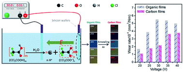
To meet the lubrication demands of future MEMS/NEMS, thickness-controllable carbon films have been successfully prepared directly on silicon substrates by carbonizing electrophoresis-deposited trichloroacetic acid (TCA) molecular films. Compared with easily worn-out TCA molecular films, the transformed carbon films exhibit ultra-low friction coefficients and wear rates, along with strong adhesion to silicon substrates. These results prove that the idea of transforming organic molecular films into carbon thin films is a unique and promising approach to fabricate thickness-controllable and wear-resistant carbon-based solid lubricants for MEMS/NEMS.
1. Introduction
Since the current raw materials for fabricating micro/nano electromechanical systems (MEMS/NEMS) are mainly non-anti-wear silicon materials, rapidly developing MEMS/NEMS have significantly increased the demand for ultrathin lubricantion films that can improve the severe wear problems between contacting surfaces at the micro/nano scale.1–3 Though carbon films fabricated by vapor deposition have superior resistance to wear and strong adhesion to substrates, they are still difficult to meet the demand of nano-scale thickness for sophisticated moving parts with many edges and corners.4,5 Therefore, many organic films with low stiction and low friction prepared by solution-based approaches have been explored for MEMS/NEMS, such as ultrathin polymer films,6 nanocomposite molecular layers,7,8 and self-assembled monolayers (SAMs).9,10 However, their anti-wear ability and adhesion to silicon substrates are much worse than carbon films, and their thicknesses are also difficult to regulate as required. Consequently, fabricating films with controllable thickness, low wear, and strong adhesion to silicon substrates is extremely urgent. We know that electrophoretic deposition (EPD) techniques possess the merits of high-precision controllability in thickness and strong adhesion to substrates.11 If these organic molecular films could be prepared by electrophoretic deposition techniques, and then transforming them into carbon films, the merits of both organic films and carbon films may be integrated into one.
We previously demonstrated that utilizing the characteristic of graphene oxide (GO) sheets easily negatively charged by carboxyl groups of their own in aqueous solution, GO films can be prepared on the anode by electrophoretic deposition techniques at lower applied voltages.12 The preparation principle of GO films is based on the fact that the negatively charged GO sheets can migrate toward anode under an electric field rather than using high excitation voltage to generate charged carbon fragments. Similarly, organic acid molecules negatively charged by carboxyl groups should also move to anode, which is completely a physical process and does not change the molecular structure and composition. Along this direction, we speculate that those organic acids ionized in water such as trichloroacetic acid (TCA) can be used as raw materials to fabricate organic molecular films. The carboxyls and chlorines in the TCA molecular films can decompose into CO2 and HCl under annealing, while the residual carbon atoms may couple together and generate carbon films.
Therefore, in this work, we have successfully prepared thickness-controllable carbon films directly on bare silicon substrates by annealing electrophoresis-deposited TCA molecular films. We characterized the variations of morphologies, crystalline states, mechanical and tribological properties of the TCA molecular films before and after annealing, and finally demonstrate that carbonizing electrophoresis-deposited organic films into carbon films is a unique approach to prepare thickness-controllable carbon-based solid lubricants for MEMS/NEMS, because it combines the merits of controllable thickness, low wear, and strong adhesion to silicon substrates that other preparation methods do not have.
2. Experimental
2.1 Materials
Trichloroacetic acid (TCA) was purchased from Shanghai Shanpu Chemical Co., Ltd. N-type polished single-crystal silicon (100) wafers with resistivity of 0.01 Ω m were bought from MCL Electronic Materials, Ltd. Ultrapure water (>18 M Ω cm−1) used throughout the experiment was purified using a Milli-Q system from Millipore Co.
2.2 Preparation of the films
Prior to deposition, all silicon wafers were cleaned in a piranha solution (a mixture of 7
:
3 (v/v) 98% H2SO4 and 30% H2O2), subsequently washed with ultrapure water several times and blown dry with N2. In a typical experiment, two symmetric silicon wafers as work electrodes were immersed into a beaker containing 0.32 mmol L−1 TCA solution, with a constant distance of 5 mm, and then connected to a DC power supply, and the corresponding films deposited at various voltages (20 V, 25 V, 30 V, 35 V, and 40 V) on the anode for an hour were denoted as TCAF20, TCAF25, TCAF30, TCAF35, and TCAF40, respectively. These films were prepared in double, one set unannealed (TCAF-u) and the other annealed (TCAF-a) at 800 °C under the protection of argon atmosphere. All experiments were carried out at room temperature.
2.3 Characterization
The values of zeta potential and conductivity of TCA in aqueous solutions were measured by Laser dynamic scattering tester (Nano ZS3600, Malvern, England). The morphologies of the films were characterized by microscope (Olympus, Japan) and atomic force microscope (Veeco Nanoscope IIIa, USA), and the thickness measurements were performed with a L116-E ellipsometer (Gaertner, America), which is equipped with a He–Ne laser (632.8 nm) set at an incident angle of 50°. A real refractive index of 1.25 is set for the silica layer. The surface roughness was also obtained by atomic force microscope (Veeco Nanoscope IIIa, USA). In addition, transmission electron microscopy (TEM, JEM-1200EX, JEOL, Japan), Raman spectroscopy (JY-HR800, the excitation wavelength at 532 nm), and X-ray photoelectron spectroscopy (XPS, ESCALAB 250Xi, Thermo Scientific) were applied to reveal the micro morphology, crystalline state, and composition of the films. The stress and the adhesion to silicon substrate for the film were measured by stress distribution tester (BGS 6341, China) and multifunctional material surface performance tester (MFT-4000), respectively. Besides, the TG curve was obtained by STA449F3 simultaneous thermal analyzer (NETZSCH, German).
Tribological experiments were conducted on a rotary friction tester (MS-T3000, China) at room temperature in ambient air. In a typical operation, the upper steel ball (φ = 3 mm) was fixed, and the lower disk was rotating. Experimental parameters were a load of 20 mN, a linear speed of 0.01 m s−1 and test duration of 30 min. But for the wear life experiment, the load was increased to 200 mN. For comparison purposes, the friction behaviors of graphitic flake and bare silicon wafer were investigated under the same conditions. The resulting cross-sectional profiles of worn tracks were obtained using a dual-mode surface three-dimensional profiler (AEP, USA). The wear volume was calculated as V (mm3) = A (mm2) × L (mm), where A is the cross-sectional area of worn scar and L is the length of the worn scar. The specific wear rate, W (mm3 Nm−1) = V (mm3)/S (m) F (N), is determined as a function of the wear volume V divided by the sliding distance S and the applied load F. All tests were carried out at least three times to ensure data repeatability.
3. Results and discussion
3.1 Preparation and characterization of the films
Trichloroacetic acid (TCA) is monocarboxylic acid that can easily ionize in aqueous solution, and its surface charge can be evaluated by zeta potential. Fig. 1a shows the zeta potential values of the TCA in aqueous solutions at different concentrations. It can be seen that the values of zeta potential are all negative when the concentration is below 1.5 mmol L−1, and the conductivity increases with concentration (Fig. 1b), which confirms that the TCA molecules are negatively charged. So when under a uniform electrical field those molecular can migrate to anode. Take advantage of this principle, the detailed electrophoretic deposition system was designed as shown in Fig. 1c. According to the TG curve of the TCA molecular film deposited at 30 V (Fig. S1†), the decomposition occurred at ∼300 °C. To ensure the organic molecular films can be completely decomposed, the TCA molecular films were annealed at 800 °C in argon atmosphere. So one set of TCA molecular films deposited at 20 V, 25 V, 30 V, 35 V, 40 V are denoted as TCAF20-u, TCAF25-u, TCAF30-u, TCAF35-u, TCAF40-u, respectively; and the other set of the films annealed at 800 °C are denoted as TCAF20-a, TCAF25-a, TCAF30-a, TCAF35-a, TCAF40-a, respectively. As Fig. 2a shows, the unannealed films look homogeneous and smooth, and the color varies with increasing voltage, so is the annealed films (Fig. 2b). Before annealing, the AFM image and the corresponding profile line (Fig. 2c) show that the TCAF30-u is composed of many nanoparticles, and the corresponding TEM image (Fig. 2d) shows an amorphous microstructure. But as shown in Fig. 2e, annealing makes TCAF30-u become denser. Importantly, the corresponding TEM image (Fig. 2f) demonstrates that TCAF30-u had been transformed into crystallized carbon with interlayer spacing of 0.34 nm.13 Also, it is confirmed by Raman spectra, as shown in Fig. 2g, the annealed TCAF30-a shows typical D (at ∼1348 cm−1) and G (at ∼1603 cm−1) peaks of carbon films, but there is no response to Raman scattering for unannealed TCAF30-u.14 These results suggest that the TCA molecular film can be easily transformed into carbon film by annealing.
 |
| Fig. 1 (a) Zeta potential and (b) conductivity of TCA in aqueous solutions at various concentrations. (c) Schematic of electrophoretic deposition for TCA molecular films. | |
 |
| Fig. 2 Optical images of the TCA films deposited at different voltages (20–40 V) on silicon wafers (a) before and (b) after annealing at 800 °C. (c and e) AFM and (d and f) TEM images of the TCA film deposited at 30 V before (c and d) and after (e and f) annealing at 800 °C, respectively. Insets (within the area outlined in white) of AFM images are the corresponding profiles. (g) Raman and (h) XPS spectra of the TCA film deposited at 30 V before (-u) and after (-a) annealing at 800 °C, respectively. | |
To reveal the evolution of the composition of TCA molecular films before (-u) and after (-a) annealing, the XPS spectra (Fig. 2h) were conducted for TCAF30-u and TCAF30-a. The C1s spectra reveal that TCAF30-u is composed of the following functional groups: carbon sp2 (C
C/C–C, ∼284.6 eV), C–Cl bonds (∼286.6 eV), and carbonyls (C
O, 288.2 eV).15 And the Cl/C atomic ratio is ∼3.73%. After annealing, however, the corresponding Cl/C atomic ratio drops to ∼0.12%, suggesting that most of C–Cl bonds were decomposed. Additionally, the carbonyl groups disappeared almost entirely in C1s spectrum of TCAF30-a, indicating that the carbonyls in the films may be removed in the form of carbon oxides under annealing. Therefore, the formation mechanism of carbon films may be a result of re-coupling of cracked carbon atoms.
3.2 Tribological study of the films
The friction curves of TCA molecular films before and after annealing are shown in Fig. 3a. For comparison, the corresponding friction coefficients are summarized in Fig. 3b. Before annealing, the friction coefficients are increasing with voltages as a whole. However, after annealing, there is a considerable reduction in friction coefficient in the range of 20–30 V; especially for TCAF30-u, the friction coefficient decreases by more than half from 0.116 to 0.052; but for TCAF35-u and TCAF40-u, their friction coefficients increase sharply. The above results suggest that the converted carbon films can greatly reduce the friction coefficients compared with the TCA molecular films. The enhanced friction performances for the converted carbon films indicate that their surface properties and internal microstructures have changed greatly.16 Hence, the variations of surface roughness are presented in Fig. 3c, which indicates that annealing greatly reduces roughness for converted films and makes them more flat and dense. Compared with the other annealed films, TCAF35-a and TCAF40-a have higher roughness, which may be responsible for their higher friction coefficients. However, TCAF30-a possesses the smallest roughness, which may contribute mostly to its excellent tribological performances. On the other hand, the changes in thickness are shown in Fig. 3d. As a whole, the thicknesses (35–250 nm) of the unannealed and annealed films are both linear with the voltage (20–40 V). It means that the thickness of the film can be precisely regulated by changing applied voltages. Consequently, the electrophoretic deposition technique is a promising method to fabricate thickness-controllable solid lubricants for MEMS/NEMS.
 |
| Fig. 3 (a) Friction coefficient curves vs. time for the TCA molecular films deposited at different voltages (20–40 V) before (-u) and after (-a) annealing at 800 °C, respectively. Conditions for friction experiments: load = 20 mN, sliding velocity = 0.01 m s−1. (b) Friction coefficient, (c) roughness and (d) thickness of the TCA molecular films deposited at different voltages (20–40 V) before (-u) and after (-a) annealing at 800 °C as a function of voltages, respectively. | |
The variations of wear rate for TCA molecular films and the converted carbon films are presented in Fig. 4a, which display that the converted carbon films deposited at 30–40 V have stronger wear resistance compared with the TCA molecular films. For instance, the wear rate of TCAF30-u is 5.48 × 10⁻⁴ mm3 Nm−1. After annealing, it can be reduced to 2.17 × 10⁻⁴ mm3 Nm−1, which is only about 1/5 and 1/32 that of bare Si wafer (1.15 × 10⁻³ mm3 Nm−1) and graphite flakes (7.04 × 10⁻³ mm3 Nm−1), respectively (Fig. S2†). Through analysis of the residual stress of TCA molecular films and the converted carbon films (Fig. 4b), we find that annealing can not only convert the TCA molecular films into carbon films but also greatly reduce their residual stresses. For example, the residual stresses of TCAF30-u is reduced from −84.5 GPa to −32.1 GPa after annealing, which could surely account for the excellent anti-wear performance of TCAF30-a. To illustrate the wear life of the converted carbon film, the load was increased tenfold (from 20 mN to 200 mN) and the corresponding friction curve is shown in Fig. 4d. Compared with the unannealed molecular films, TCAF30-a shows a longer life span (up to 175 minutes) which is almost twice longer than that of TCAF30-u, and meanwhile with the lower friction coefficient (0.131). More importantly, the carbon film transformed from TCAF30-u has strong adhesion to substrate (up to 7.6 N) (Fig. 4c), which is considerably larger than that of organic molecular film of TCAF30-u (2.7 N). These enhancements in wear resistance (low wear rate, long wear life) and adhesion to substrate further confirm that the converted carbon film is a more excellent solid lubricant than organic molecular film. Therefore, transforming electrophoresis-deposited organic molecular films into carbon films by annealing is a promising approach to fabricate thickness-controllable carbon-based solid lubricants for MEMS/NEMS.
 |
| Fig. 4 Variations in (a) wear rate, (b) internal stress, and (c) adhesion of the TCA molecular films deposited at different voltages (20–40 V) before (-u) and after (-a) annealing at 800 °C as a function of voltages, respectively. (d) Wear life comparison for the TCA molecular films deposited at 30 V before (TCAF30-u) and after (TCAF30-a) annealing. | |
4. Conclusions
In summary, electrophoresis technique is robust, allowing us to obtain thickness-controllable (35–250 nm) organic molecular films by adjusting applied voltage. Therefore, uniform and anti-wear carbon films can be obtained directly on silicon wafers by carbonizing the corresponding electrophoresis-deposited TCA molecular films. The surface roughness of the carbon film varies with applied voltage, which is responsible for the lower friction coefficient of the optimized carbon film (TCAF30-a). Importantly, compared with TCA molecular films, the converted carbon film also greatly extends life span, along with stronger adhesion to silicon, which is attributed to the reduction of internal stress and the changes of microstructures in the process of transformation. Unambiguously, the converted carbon films combine the merits of ordinary carbon films and electrophoresis-deposited organic films. Therefore, the idea of carbonizing electrophoresis-deposited organic films into carbon films opens up a new avenue to construct thickness-controllable and wear-resistant carbon films for potential applications to MEMS/NEMS devices.
Acknowledgements
This work was supported by Key Basic Research Project of China (973 Program, 2013CB632300), National Natural Science Foundation of China (51475447, 51305434).
Notes and references
- I. Ku, T. Reddyhoff, A. Holmes and H. Spikes, Wear, 2011, 271, 1050 CrossRef CAS PubMed.
- S. Shen and Y. Meng, Tribol. Lett., 2012, 47, 273 CrossRef CAS.
- V. V. Tsukruk, Adv. Mater., 2001, 13, 95 CrossRef CAS.
- C. Donnet and A. Erdemir, Surf. Eng., 2008, 24, 399 CrossRef CAS PubMed.
- R. Colaco, A. P. Serro, O. L. Eryilmaz and A. Erdemir, J. Phys. D: Appl. Phys., 2009, 42, 085307 CrossRef.
- S. L. Ren, S. R. Yang and Y. P. Zhao, Appl. Surf. Sci., 2004, 227, 293 CrossRef CAS PubMed.
- S. Y. Gao and L. G. Yu, Chin. J. Chem. Phys., 2002, 15, 132 CAS.
- M. Minn, Y. S. G. Soetanto and S. K. Sinha, Tribol. Lett., 2011, 41, 217 CrossRef CAS.
- P. Cong, T. Kubo, H. Nanao, I. Minami and S. Mori, Tribol. Lett., 2007, 27, 137 CrossRef CAS.
- F. Q. Fan, X. D. Li and T. Miyashita, Thin Solid Films, 1999, 348, 238 CrossRef CAS.
- S. He, Y. Zhao, M. Wei and X. Duan, Ind. Eng. Chem. Res., 2011, 50, 2800 CrossRef CAS.
- H. Liang, Y. Bu, J. Zhang, Z. Cao and A. Liang, ACS Appl. Mater. Interfaces, 2013, 5, 6369 CAS.
- M. Zhao, H.-H. Song, W.-T. Lian, X.-H. Chen, X.-D. Tian and L. Chen, J. Inorg. Mater., 2007, 22, 599 CAS.
- A. C. Ferrari, New Diamond Front. Carbon Technol., 2004, 14, 87 CAS.
- E. Papirer, R. Lacroix, J.-B. Donnet, G. Nansé and P. Fioux, Carbon, 1995, 33, 63 CrossRef CAS.
- J. J. S. Dilip, S. Babu, S. V. Rajan, K. H. Rafi, G. D. J. Ram and B. E. Stucker, Mater. Manuf. Processes, 2013, 28, 189 CrossRef CAS.
Footnote |
† Electronic supplementary information (ESI) available: TG curve of TCAF30-u; friction coefficient vs. time curves and 2D profile plots of wear tracks for graphite flake and bare silicon wafer, respectively. See DOI: 10.1039/c5ra01400j |
|
This journal is © The Royal Society of Chemistry 2015 |
Click here to see how this site uses Cookies. View our privacy policy here.