Superhydrophobic Ti6Al4V surfaces with regular array patterns for anti-icing applications

Yizhou Shen, Jie Tao*, Haijun Tao, Shanlong Chen, Lei Pan and Tao Wang
College of Material Science and Technology, Nanjing University of Aeronautics and Astronautics, Nanjing 210016, P. R. China. E-mail: taojie@nuaa.edu.cn; Fax: +86 25 5211 2911; Tel: +86 25 5211 2911

Received 23rd January 2015 , Accepted 31st March 2015

First published on 1st April 2015


Abstract

In this article, we present a route to fabricate a robust anti-icing superhydrophobic surface containing the hierarchical structures of microscale array patterns (built by micromachining) and nanohairs (prepared via hydrothermal growth) on a Ti6Al4V substrate. In particular, the superhydrophobic surfaces not only exhibited high non-wettability and water repellency, but also generated a tremendous anti-icing potential. The results of the measurements indicated that the apparent contact angle reached 160°, the contact angle hysteresis reduced to 2°, and the spreading and recoiling process of an impact droplet can be completed within 12 ms. Furthermore, it also caused a longer icing-delay time (approximately 765 s) to hinder the ice formation and growth at −10 °C, and the ice adhesion strength was also only 70 kPa.

Introduction

Ice accretion on the surface of aircraft has been a serious threat to the safety of flights owing to the increase of aerodynamic drag, the reduction of lift force, and causing some sensor failure.1–3 Aircraft icing is mainly caused by a large number of supercooled water droplets hidden in the cloud, and mostly occurs on the leading edge of the wings and tail. During recent decades, many researchers devote themselves to design, prepare, and partly apply all kinds of anti-icing coatings to prevent the ice formation and accumulation.4–6 In their opinion, compared to some traditional methods like mechanical, electrothermal, and liquid hybrid methods, designing anti-icing coatings without an additional deicer is a more exciting approach due to improving the fuel efficiency and increasing the effective load of aircrafts. Considering the first step of ice accretion on the surface of aircrafts (i.e., the process of supercooled water droplet wetting), candidate anti-icing coatings should owns very strong non-wettability/repellency to prevent ice formation.7

Bioinspired by the lotus leaf, peanut leaf, cicada wing, and butterfly wing, researchers consistently consider the superhydrophobic surfaces with a water contact angle greater than 150° and an extremely low sliding angle no more than 10° as the most ideal choice for anti-icing applications.8–11 Superhydrophobic surfaces can delay effectively ice formation due to the existence of air pockets trapped inside the surface microstructures.12,13 The air pockets can form a thermal barrier between the solid surface and supercooled water droplet to prevent heat transfer. Moreover, water droplets have a very small contact area with superhydrophobic surfaces, which further reduces thermal conversion efficiency.14,30 Furthermore, according to some results reported by recent literatures, ice adhesion on the superhydrophobic surface is far less than that on the substrate, resulting in ice easily falling off from the surface under the action of airflow.15

Through the investigations on both natural and artificially fabricated superhydrophobic surfaces,16,17 it has been well established that the main elements causing the non-wettability of a solid surface are chemical component (or surface free energy) and geometrical microstructure (or surface roughness). On a smooth surface, the contact angle of a water droplet can be increased to only 120° by lowering the surface free energy (the lowest surface free energy, 6.7 mJ m−2, attained for a surface with regularly aligned closest-hexagonal-packed CF3 groups).18,19 However, adding the construction of micro-nanostructures can lead to the contact angle of water droplets reaching 150° or beyond, the sliding angle being also no more than 10°. Thus, understanding, controlling, and building surface textures are critical to obtain superhydrophobic surfaces with high non-wettability.

Currently, micro-/nanostructures have been constructed to obtain superhydrophobicity by many approaches such as chemical etching, laser or plasma etching, physical or chemical vapor deposition, sol–gel, spraying, phase separation, and anodic oxidation.20–24 Changmin Hu and his co-workers25 designed and fabricated a micro-nanometer rough structure to prepare superhydrophobic surfaces through one-step co-electrospraying poly and the modified silica nanoparticles. Inspired by fish scales, Lei Jiang used dislocation etching to build micro-nanoscale composite structures (pillars with the dimensions of 150 μm × 150 μm and silicon nanowires) on the silicon wafers, and obtained the low adhesion water/solid interface.26 Meanwhile, Sungbo Jin's group in University of California reported unprecedented superomniphobic characteristics of nanotube-structured TiO2 surface prepared by the combination of electrochemical etching for microscale structure and hydrothermal synthesis process for nanoscale structure, with the both wettability contact angles for water and oil being approximately 174°.27 To sum up, researchers can successfully fabricate micro-/nanostructures on metal or silicon substrates to obtain superhydrophobicity. However, considering the anti-icing of the surface of aircrafts, we need to prepare the superhydrophobic anti-icing surfaces on the Ti or Al alloy substrates, and the surface textures should have the ability to trap a large amount of air under the droplets. Current strategies to construct the micro-nanoscale hierarchical structures in metal substrates may be hard to obtain the controllable regular microscale patterns comparing to the nanoscale array. Some other advanced technologies, such as electron beam lithography and plasma etching, are usually used to fabricate micro/nanoscale structures on the surfaces of silicon materials.28 Furthermore, we did try to construct some regular microscale patterns on Ti6Al4V or pure Ti substrates using the electron beam lithography and plasma etching techniques. The results indicated that the etching depth (approximately 3 μm) of the microscale patterns was much less than the design value. However, the controllable regular microscale patterns are of important significance to design the anti-icing surfaces, because they tend to trap more air pockets under the droplets or ice.

In this paper, we reported a route to fabricate the hierarchical structures of microscale regular arrays and nanohairs on Ti6Al4V substrate, and obtained superhydrophobic surface via the modification with fluoroalkylsilane (FAS-17). The superhydrophobicity was evaluated via the characterizations of static/dynamic contact angles and the contact process of an impact droplet. In addition, its anti-icing potential was investigated via testing the icing-delay time of a droplet on this superhydrophobic surface and the ice adhesion strength. This study was of significance to design superhydrophobic anti-icing surface.

Experimental section

Materials

Ti6Al4V titanium alloy purchased from Baoji Titanium Industry Co., Ltd., China was manufactured into small pieces with the size of 10 mm × 10 mm × 1 mm. SU-8 photoresist was obtained from the Gersteltec Sarl Co., Ltd., Switzerland. All the chemicals used in this experiment were analytical grade and provided by Sinopharm chemical reagent Co., Ltd., China. Additionally, as a modification agent, commercial grade heptadecafluorodecyl trimethoxysilane (FAS-17, purchased from Tokyo chemical industry Co., Ltd., Japan) was used to modify the micro-nanohierarchical structures.

Experimental procedure

Fig. 1 shows the process of micromachining of the controllable regular microscale patterns on Ti6Al4V substrate. Simply, the manufactured Ti6Al4V small piece (10 mm × 10 mm × 1 mm) was mechanically polished to obtain a flat surface, and covered by a photoresist. The photoresist was selectively exposed using a standard UV mask aligner, and developed to the initial patterns (square array patterns with the size of 50 μm × 50 μm in this experiment).29 Subsequently, chemical micromachining was performed in the mixed solution of 35 mL L−1 HF and 70 mL L−1 HNO3 for 6 min. After stripping, the controllable regular microscale patterns could be obtained on substrate.
image file: c5ra01365h-f1.tif
Fig. 1 The process of micromachining of the controllable regular microscale patterns.

To plant a layer of nanohairs on the surface of the regular array patterns, the sample was placed in an autoclave with 30 mL 1 M NaOH aqueous in a 220 °C oven for 2.5 h, then sufficiently rinsed with deionized water and immersed with a dilute 0.1 M HCl aqueous solution for 0.5 h. Subsequently, an annealing process at 500 °C (heating rate is 2 °C min−1) for 3 h was necessary to produce TiO2 nanohairs.30 Finally, the sample was immersed in 1 wt% FAS-17 ethanol solution for 24 h and then dried in a 120 °C oven for 2 h to obtain the superhydrophobic surface. Furthermore, we designed three kinds of surfaces for a comparative study, (Sample 1) Ti6Al4V substrate surface with FAS-17 modification; (Sample 2) nanohair structured surface with FAS-17 modification; (Sample 3) hierarchical structured (microscale regular arrays and nanohairs) surface with FAS-17 modification.

Characterizations and anti-icing potential test

The morphologies of the sample were observed using a field emission scanning electron microscopy (FE-SEM; Hitachi S4800, Japan), and the height of the regular microscale patterns was characterized by a 3D microscope (Leica DVM 5000, Germany). The chemical component of the surfaces was studied by X-ray photoelectron spectroscopy (XPS) using an X-ray photoelectron spectrometer (Kratos AXIS UltraDLD, Japan). The apparent contact angle (APCA), advancing contact angle (ACA), receding contact angle (RCA), and contact angle hysteresis (CAH) (i.e., the difference between ACA and RCA) of a 4 μL water droplet on the surfaces of these samples were measured by a contact angle analyzer (Kruss DSA100, Germany), and the average value of three measurements was determined. In order to ensure the 4 μL water droplet successfully dripping down, we chose the ultrafine hydrophobicated needle with the inner diameter of only 0.03 mm.

Fig. 2 shows the schematic diagram of a self-made icing-delay time measurement device. The reference droplets (4 μL) were placed on the surfaces of these samples and the temperature was controlled at −10 °C, and the icing process of the droplet was observed by a CCD camera. The icing-delay time can be directly obtained from the CCD camera. The ice adhesion strength at −10 °C was measured via a similar device, and the operation procedure was reported in our previous article.31


image file: c5ra01365h-f2.tif
Fig. 2 Schematic diagram of a self-made icing-delay time measurement device.

The CCD camera was also used to record the contact process of an impact droplet to the surfaces of these samples, and the contact time was directly obtained from the CCD camera. In this measurement, the droplets were released from a fixed height of 50 mm over the sample surfaces.

Results and discussion

Preparation of superhydrophobic surfaces

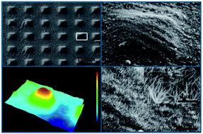
Preparation of superhydrophobic surfaces is based on the combination of micro-/nanostructure and surface chemical component. The constructed surface micro-nanohierarchical structures are shown in Fig. 3. It can be seen from the FE-SEM images that the average size of the microscale array patterns is about 50 μm × 50 μm with the spacing of 50 μm (seeing Fig. 3a), and the height of approximately 11 μm, as shown in Fig. 3c. The microscale array patterns are completely covered by a layer of nanohairs produced via the hydrothermal synthesis, as shown in Fig. 3b. Meanwhile, Fig. 3d reveals that the nanohair structures are uniformly distributed, and the length is approximately 1 μm (inset in Fig. 3d).
image file: c5ra01365h-f3.tif
Fig. 3 Images of the micro-nanohierarchical structures of sample 3. (a) FE-SEM image of the regular microscale array patterns; (b) high-magnification images of area marked with white open rectangle in (a); (c) 3D micrograph of one pattern in the surface of sample 3; (d) higher magnification images of nanohairs planted on the surface of the microscale array patterns.

In order to obtain superhydrophobicity, modifying with FAS-17 is necessary to be performed to gain a low surface energy chemical component. Fig. 4 illustrates the surface chemical components of the sample before and after modifying with FAS-17. It can be seen that the sample possesses high intensity peaks of the F1s and FKLL and low intensity peaks of the Ti2p and O1s after modifying with FAS-17. Also, in the high resolution spectrum of C1s, the peaks corresponding to –CF2 (at 291 eV) and –CF3 (at 294 eV) are observed, indicating that the fluoroalkyl groups in FAS-17 have been self-assembled onto the surfaces of the micro-nanohierarchical structures.


image file: c5ra01365h-f4.tif
Fig. 4 Survey and high resolution (inset) XPS spectrum of the samples before and after modifying with FAS-17.

Non-wettability for superhydrophobicity

In this section, we present the demonstration and analysis of non-wettability of Sample 1, Sample 2, and Sample 3 around two aspects (i.e., static/dynamic contact angles and the contact process of an impact droplet). Fig. 5 depicts the results of contact angle measurements including APCA, ACA, RCA, and CAH. We can find that, comparing with Sample 1, APCAs of the droplets on the surfaces of Sample 2 and Sample 3 are both up to 152° and 160° respectively, both giving a nearly spherical water droplet. Moreover, the CAHs also reduce to 5° and 2° respectively. These indicate that the two surfaces (i.e., Sample 2 and Sample 3) possess the strong non-wettability, but some difference can also be easily found.
image file: c5ra01365h-f5.tif
Fig. 5 APCA, ACA, RCA, and CAH of a droplet on the surfaces of the three samples, (inset) the dynamic images of droplets on these surfaces.

Such high apparent contact angles and low contact angle hysteresis may be expected. According to the observations of the surface textures, we give the wetting models of the droplets on the surfaces of Sample 2 and Sample 3, as shown in Fig. 6. The both wetting phenomena above can be elucidated in detail by Cassie–Baxter model, demonstrating that surface microstructures play a key role in enhancing the superhydrophobicity.32 In the two cases, the apparent contact interface of water droplet and surface is actually composed of liquid/solid and liquid/gas. This is consistent with Cassie–Baxter equation:

 
cos[thin space (1/6-em)]θ* = f1[thin space (1/6-em)]cos[thin space (1/6-em)]θ1 + f2[thin space (1/6-em)]cos[thin space (1/6-em)]θ2 (1)


image file: c5ra01365h-f6.tif
Fig. 6 Wetting models of the droplets on the surfaces of (a) Sample 2 and (b) Sample 3.

In this equation, θ* is the apparent contact angle (i.e., APCA) of the water droplet on the surface, θ1 and θ2 represent the Young's contact angles of the droplet on the solid and air, f1 and f2 are the contact area fractions of the liquid droplet on the solid and air respectively, and f1 + f2 = 1. Considering that the Young's contact angle of the droplet on air is 180° (i.e., non-wetting), eqn (1) becomes:

 
cos[thin space (1/6-em)]θ* = f1[thin space (1/6-em)]cos[thin space (1/6-em)]θ1 + f1 − 1 (2)

Thus, we can draw the conclusion that reducing the contact area fractions (f1) of the liquid droplet on the solid is very important to improve the non-wettability of superhydrophobic surfaces. The nanohairs prepared by hydrothermal treatment have very large roughness, resulting in more air pockets being trapped under the droplet, and the extremely small f1. Thus, the surface with nanohairs (i.e., Sample 2) exhibits the strong superhydrophobicity (APAC of ∼152°; CAH of ∼5°). Addition of microscale array patterns to the nanohair structure leads to a smaller f1, as shown in Fig. 6b, and greatly enhances the non-wettability with APCA reaching 160° and CAH reducing to 2° (i.e., Sample 3). These demonstrate that microscale structure is also of great importance to improve the non-wettability of superhydrophobic surfaces.

Furthermore, we recorded the contact process of the impact droplets with the speed of 1 m s−1 using a CCD camera, as shown in Fig. 7. It can be seen that the processes of droplet spreading a nearly uniform coating (before approximately 6 ms) on the three sample surfaces are almost same. However, there is an obvious difference in the recoiling process among the three sample surfaces. The droplets impacting the surface of Sample 1 cannot lift off owing to the strong adhesion. The recoiling processes of droplets on surfaces of Sample 2 and Sample 3 spend about 8 ms and 6 ms, respectively. The difference could be attributed to the amount of air trapped under the droplets. According to the above discussion, the addition of microscale array patterns to the nanohair structures favors to induce more air pockets under the droplet. And it can be found that the overall contact time of impact droplets on Sample 3 surface is extended to approximately 17 ms at −10 °C. The time is still far less than the icing-delay time of droplets on the surfaces, resulting in the impact droplets bouncing off before freezing. Thus, the superhydrophobic surface with the composite structures of microscale array patterns and nanohairs exhibits the robust non-wettability and water repellency.


image file: c5ra01365h-f7.tif
Fig. 7 The processes of impact droplets with the speed of 1 m s−1 on the surfaces of Sample 1, Sample 2, and Sample 3 at room temperature, and Sample 3 at −10 °C.

Anti-icing potential

As an important application, the anti-icing potential of Sample 3 should be still probed around the two aspects of icing-delay performance and ice adhesion strength, despite this being an argumentative issue.33–36 The reference droplets are deposited on these sample surfaces and observed how long the droplets are maintained before completely freezing (i.e., icing-delay time). Fig. 8 shows the icing processes of droplets on these surfaces at −10 °C. The droplet on the surface of Sample 1 is quickly frozen (13.2 s). However, the droplets on the other surfaces (i.e., Sample 2 and Sample 3) take a long time to completely freeze, especially the droplet on the surface of Sample 3 (765 s). Moreover, we find that precooling the droplets (before ice growing) spends most of the time (746 s for this process in the icing-delay time measurement of Sample 3). Thus, the superhydrophobic surfaces exhibit a high anti-icing potential with the icing-delay time up to 599 s (Sample 2) and 765 s (Sample 3).
image file: c5ra01365h-f8.tif
Fig. 8 Optical images of the icing processes of 4 μL droplets on the surfaces of Sample 1, Sample 2, and Sample 3 at −10 °C.

From the view of thermodynamics, the droplet on the cold surface gains heat from air in forms of heat conduction and thermal radiation, and loses heat to the cold surface through heat conduction. The reduced energy of droplet can be expressed as:37

 
ΔQ = Q1Q2 (3)
where ΔQ is the net heat increase in unit time; Q1 is the heat gain from the air, and Q2 is the heat loss to the cold contact solid surface. Furthermore, for the reference droplet, the reduced temperature can be expressed as:
 
image file: c5ra01365h-t1.tif(4)
where ΔT is the reduced temperature of droplet; ρw is the water density; Cp is the specific heat capacity of water; T0 is the starting temperature of the droplet; T1 is the sample surface temperature. The eqn (3) and (4) indicate that a small Q2 or a large Q1 can cause a large ΔQ, and finally result in a small ΔT. Thus, it can explain why a droplet suspending on the superhydrophobic surfaces (i.e., Sample 2 and Sample 3) takes a longer icing-delay time comparing with the non-structured surface (i.e., Sample 1). Moreover, Sample 3 exhibits a higher icing-delay performance than Sample 2, because the microscale array patterns with the nanohair structures favors to trap more air pockets between the droplet and solid surface, as revealed in Fig. 6.

Although superhydrophobic surfaces have a strong icing-delay performance, the ice growth still occurs after a certain amount of freezing time in subzero environment. To systematically evaluate the anti-icing potential, we test the ice adhesion strength at −10 °C via a self-made measurement device. It can be found in Fig. 9 that the ice adhesion strength on the surface of Sample 3 (approximately 70 kPa) is much lower than those on the other sample surfaces (700 kPa for Sample 1 and 190 kPa for Sample 2). The variation rule of ice adhesion strength is agreement with the reported results by B. J. Basu.38 Furthermore, ice adhesion strength on the surface of Sample 3 is slightly less than that (80 kPa) on the superhydrophobic surface prepared by a combination of sand blasting and hydrothermal growth.31


image file: c5ra01365h-f9.tif
Fig. 9 The ice adhesion strength on Sample 1, Sample 2, and Sample 3 at −10 °C.

According to the wetting models of the droplet on these surfaces, the ice adhesion strength is mainly depended on the contact area fractions (f1) of the liquid droplet on the solid. Moreover, the wetting regimes of droplets on the surfaces of Sample 2 and Sample 3 can be both explained by Cassie–Baxter Model. Therefore, the actual contact interface between ice and superhydrophobic surface is composed of ice/air and ice/hydrophobic solid, leading to a lower ice adhesion strength comparing to the Sample 1. Unlike the surface structure of Sample 2, Sample 3 with microscale array patterns and nanohair structures has the ability to induce more air pockets. Additionally, the breakage of the contact between ice and superhydrophobic surface practically occurs only along the real contact interface between ice and solid. Thus, the measured ice adhesion strength on surface of Sample 3 is much smaller than those on other surfaces.

Conclusions

In conclusion, we designed and novelly fabricated a robust anti-icing superhydrophobic Ti6Al4V surface containing the hierarchical structures of microscale array patterns (built by micromachining) and nanohairs (prepared via hydrothermal growth). By this combination, the superhydrophobic surface exhibited a strong non-wettability with APCA of 160°, CAH of 2°, and the contact time of the spreading and recoiling processes within 12 ms. Moreover, the superhydrophobic surface generated a longer icing-delay time (approximately 765 s) to hinder the ice formation and growth at −10 °C, and the ice adhesion strength was only 70 kPa, exhibiting a higher anti-icing potential. This design and fabrication strategy will be of significance for investigating new anti-icing materials.

Acknowledgements

The authors gratefully acknowledge the financial support of the National Science Foundation of China (no. 51475231, no. 51202112), A Project Funded by the Priority Academic Program Development of Jiangsu Higher Education Institutions, the Jiangsu Innovation Program for Graduate Education (KYLX_0261) and the Fundamental Research Funds for the Central Universities.

Notes and references

  1. C. Antonini, M. Innocenti, T. Horn, M. Marengo and A. Amirfazli, Cold Reg. Sci. Technol., 2011, 67, 58–67 CrossRef PubMed.
  2. L. B. Boinovich and A. M. Emelyanenko, Mendeleev Commun., 2013, 23, 3–10 CrossRef CAS PubMed.
  3. T. V. J. Charpentier, A. Neville, P. Millner, R. W. Hewson and A. Morina, J. Colloid Interface Sci., 2013, 394, 539–544 CrossRef CAS PubMed.
  4. J. Xiao and S. Chaudhuri, Langmuir, 2012, 28, 4434–4446 CrossRef CAS PubMed.
  5. K. Li, S. Xu, W. Shi, M. He, H. Li, S. Li, X. Zhou, J. Wang and Y. Song, Langmuir, 2012, 28, 10749–10754 CrossRef CAS PubMed.
  6. J. Chen, R. Dou, D. Cui, Q. Zhang, Y. Zhang, F. Xu, X. Zhou, J. Wang, Y. Song and L. Jiang, ACS Appl. Mater. Interfaces, 2013, 5, 4026–4030 CAS.
  7. O. Parent and A. Ilinca, Cold Reg. Sci. Technol., 2011, 65, 88–96 CrossRef PubMed.
  8. Y. Shen, H. Tao, S. Chen, Y. Xie, T. Zhou, T. Wang and J. Tao, Appl. Surf. Sci., 2014, 321, 469–474 CrossRef CAS PubMed.
  9. H. Teisala, M. Tuominen and J. Kuusipalo, Adv. Mater. Interfaces, 2014, 1, 130026–130045 Search PubMed.
  10. X. Zhang, L. Wang and E. Levänen, RSC Adv., 2013, 3, 12003–12020 RSC.
  11. Q. Zhang, M. He, J. Chen, J. Wang, Y. Song and L. Jiang, Chem. Commun., 2013, 49, 4516–4518 RSC.
  12. A. J. Meuler, J. D. Smith, K. K. Varansai, J. M. Mabry, G. H. Mckinley and R. E. Cohen, ACS Appl. Mater. Interfaces, 2010, 2, 3100–3110 CAS.
  13. Z. Y. Deng, W. Wang, L. H. Mao, C. F. Wang and S. Chen, J. Mater. Chem. A, 2014, 2, 4178–4184 CAS.
  14. M. Wen, L. Wang, M. Zhang, L. Jiang and Y. Zheng, ACS Appl. Mater. Interfaces, 2014, 6, 3963–3968 CAS.
  15. S. A. Kulinich and M. Farzaneh, Appl. Surf. Sci., 2009, 255, 8153–8157 CrossRef CAS PubMed.
  16. M. Liu, Y. Zheng, J. Zhai and L. Jiang, Acc. Chem. Res., 2010, 43, 368–377 CrossRef CAS PubMed.
  17. E. Bormashenko and V. Starov, Colloid Polym. Sci., 2013, 291, 343–346 CAS.
  18. Y. Xiu, L. Zhu, D. W. Hess and C. P. Wong, Nano Lett., 2007, 7, 3388–3393 CrossRef CAS PubMed.
  19. T. Nishino, M. Meguro, K. Nakamae, M. Matsushita and Y. Ueda, Langmuir, 1999, 15, 4321–4323 CrossRef CAS.
  20. D. Kontziampasis, G. Boulousis, A. Smyrnakis, K. Ellinas, A. Tserepi and E. Gogolides, Microelectron. Eng., 2014, 121, 33–38 CrossRef CAS PubMed.
  21. P. Roach, N. J. Shirtcliffe and M. I. Newton, Soft Mater., 2008, 4, 224–240 RSC.
  22. J. Wang, X. Song, R. Li, J. P. Shen, G. C. Yang and H. Huang, Appl. Surf. Sci., 2012, 258, 9782–9785 CrossRef CAS PubMed.
  23. A. Hozumi, B. Kim and T. J. McCarthy, Langmuir, 2009, 25, 6834–6840 CrossRef CAS PubMed.
  24. J. Liu, W. Huang, Y. Xing, R. Li and J. Dai, J. Sol-Gel Sci. Technol., 2011, 58, 18–23 CrossRef CAS.
  25. C. Hu, S. Liu, B. Li, H. Yang, C. Fan and W. Cui, Adv. Healthcare Mater., 2013, 2, 1314–1321 CrossRef CAS PubMed.
  26. M. Liu, S. Wang, Z. Wei, Y. Song and L. Jiang, Adv. Mater., 2009, 21, 665–669 CrossRef CAS.
  27. H. Kim, K. Noh, C. Choi, J. Khamwannah, D. Villwock and S. Jin, Langmuir, 2011, 27, 10191–10196 CrossRef CAS PubMed.
  28. R. Near, C. Tabor, J. Duan, R. Pachter and M. El-Sayed, Nano Lett., 2012, 12, 2158–2164 CrossRef CAS PubMed.
  29. C. Madore and D. Landolt, J. Micromech. Microeng., 1997, 7, 270–275 CrossRef CAS.
  30. L. F. Que, Z. Lan, W. X. Wu, J. H. Wu, J. M. Lin and M. L. Huang, J. Power Sources, 2014, 266, 440–447 CrossRef CAS PubMed.
  31. Y. Shen, H. Tao, S. Chen, L. Zhu, T. Wang and J. Tao, RSC Adv., 2015, 5, 1666–1672 RSC.
  32. J. Bico, U. Thiele and D. Quéré, Colloids Surf., A, 2002, 206, 41–46 CrossRef CAS.
  33. M. Nosonovsky and V. Hejazi, ACS nano, 2012, 6, 8488–8491 CrossRef CAS PubMed.
  34. S. Jung, M. Dorrestijn, D. Raps, A. Das, C. M. Megaridis and D. Poulikakos, Langmuir, 2011, 27, 3059–3066 CrossRef CAS PubMed.
  35. S. A. Kulinich, S. Farhadi, K. Nose and X. W. Du, Langmuir, 2011, 27, 25–29 CrossRef CAS PubMed.
  36. J. Chen, J. Liu, M. He, K. Li and D. Cui, Appl. Phys. Lett., 2012, 101, 111603 CrossRef PubMed.
  37. P. Guo, Y. Zheng, M. Wen, C. Song, Y. Lin and L. Jiang, Adv. Mater., 2012, 24, 2642–2648 CrossRef CAS PubMed.
  38. T. Bharathidasan, S. V. Kumar, M. S. Bobji, R. P. S. Chakradhar and B. J. Basu, Appl. Surf. Sci., 2014, 314, 241–250 CrossRef CAS PubMed.

This journal is © The Royal Society of Chemistry 2015
Click here to see how this site uses Cookies. View our privacy policy here.