Formation of liquid rope coils in a coaxial microfluidic device†
Soichiro Tottoriab and
Shoji Takeuchi*ab
aInstitute of Industrial Science, The University of Tokyo, Fw-205, 4-6-1 Komaba, Meguro-ku, Tokyo 153-8505, Japan. E-mail: takeuchi@iis.u-tokyo.ac.jp
bTakeuchi Biohybrid Innovation Project, Exploratory Research for Advanced Technology (ERATO), Japan Science and Technology (JST), Japan
First published on 2nd April 2015
Abstract
We have studied the instability of viscous liquid threads in less viscous liquids flowing in glass coaxial microchannels. Similar to the behavior of relatively non-viscous liquid threads falling in air, liquid threads in a fluid were found to form not only coils but also two-dimensional folds, depending on the flow rates and viscosities of the fluids. We examined the effect of the flow rate ratio, physical properties of the two fluids, and channel geometries on the liquid thread thickness, pitch, and amplitude of the folding and coiling in the microfluidic channel. Additionally, the viscous liquid threads were used as templates to form hydrogel microfibers by sufficiently delaying the gelation speed of the inner fluids until folds or coils were formed and stabilized.
Streams of viscous fluid falling under gravity onto surfaces show periodic coiling patterns. This phenomenon was named the “liquid rope-coil effect” by Barnes and Woodcock.1 This fluid effect has been investigated both theoretically and experimentally.2–4 Recently, it was demonstrated that the morphology of viscous threads exhibit not only coiling but also folding, depending on the viscosity, fall height, and flow rate.5 Compared to the number of works on liquid threads falling under gravity in air, there is much less known about threads entering another liquid. Cubaud et al. performed intensive studies on the instability of two liquids with large viscosity differences in planar diverging microchannels.6–8 However, in such planar microchannels, thread deformation is confined in two dimensions. Consequently, the transition between different folding regimes, e.g., from straight to coiled threads, which is essential to understand the phenomena, has not yet been investigated.
Recently, coaxial microfluidic devices have been used to fabricate hydrogel microfibers for cell scaffolding.9–14 For specific cells, control of the cellular orientation is essential in order to realize proper functions of organs and tissues. However, the previous methods have been limited to fabricating only fibers with different cross sectional patterns. A general fabrication method of circumferentially oriented hydrogel fibers has a potential to enable cellular scaffolds with the ability to precisely control cellular orientation.15
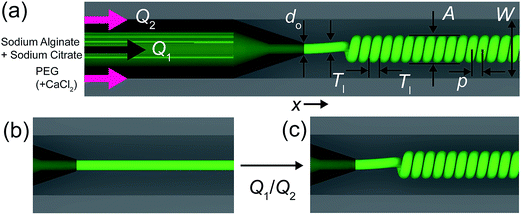
In this study, we investigated the different states of liquid threads using co-axial glass capillary microfluidic channels (Fig. 1a). The viscous and less viscous liquids are pumped through the inner and outer capillaries, respectively. The flow rates in the inner and outer channels are individually controlled. When the outer flow velocity is sufficiently greater than the inner flow velocity, the inner flow is stretched and becomes straight (Fig. 1b). As the ratio of the two flow rates (inner flow rate/outer flow rate) increases, the liquid thread (inner flow) starts to deform and forms a coil, similar to the liquid rope coiling effect in air (Fig. 1c). We examined the changes in the thickness of the liquid threads, pitch, and amplitude of the folding and coiling in the microfluidic channel caused by varying the flow rates, physical properties of the two fluids, and channel geometries. Moreover, these flow patterns were used as templates for formation of folded and coiled hydrogel microfibers, whose morphologies were tuned by changing the parameters of fluid flows and channel geometries.
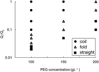
To characterize the morphology of the viscous liquid threads, we varied the flow rate ratio and viscosity of the fluids. The morphology transitions are summarized in Fig. 3 (do = 88 μm). These results clearly show an increase in the flow rate ratio Q1/Q2 at which the transitions from straight to two-dimensional folds and from two-dimensional folds to coils were observed as the viscosity of the outer fluid was increased. In comparison with the rotatory folding of liquid ropes in air reported previously,5 a large range in which multiple states coexist was not observed in our coaxial flow system. The transition observed here is similar to the pattern of viscous threads falling onto a steadily moving horizontal belt, known as ‘fluid-mechanical sewing machine’.17 In our experiment, the less viscous outer flow acts similar to the sliding solid surface of fluid-mechanical sewing machine. As the flow directions of inner and outer flow are parallel, not perpendicular to each other as used in fluid-mechanical sewing machine, the coiling shape is preserved in the flow.
 | ||
| Fig. 3 Phase diagram of the morphology of the inner flow. The inner fluid is the aqueous solution of sodium alginate 4% w/w and sodium citrate 200 mM. The diameter of inner capillary is do = 88 μm. | ||
The characteristic lengths of the inner liquid threads, i.e. the thickness Tl and amplitude A of the inner liquid threads, were measured at various distances (x) from the tip of the inner capillary (Fig. 3). At small flow rate ratios (e.g., Q1/Q2 = 1/100 for do = 88 μm, inner fluid: 4% w/w sodium alginate and 200 mM sodium citrate, outer fluid: 100 g L−1 PEG), the thickness of the inner liquid thread decreased from that of the diameter of the capillary tip once it entered the outer fluid (Fig. 4a). As the outer flow rate decreased, the thickness of the liquid threads gradually increased along the flow direction and then reached a constant value (Fig. 3b, e.g., Q1/Q2 = 1/10 and 1/20). At even larger flow rate ratios (e.g., Q1/Q2 > 1/5), the coils started to pack and the thickness of the threads decreased; in this case, the thickness of the threads was measured as the short axis of the cross section of the threads (Fig. S2†). The thickness of the liquid thread before coiling/folding is characterized as a function of flow rate ratio in Fig. 4b. The thickness of straight viscous thread can be estimated using the analytical solution for a circular channel: Tl/W ∼ (Q1/2Q2)1/2.16 As the flow rate ratio increased, liquid threads formed coils/fold. Thus, at higher flow rate ratios the thickness no longer followed Tl/W ∼ (Q1/2Q2)1/2 and reached a plateau. Fig. 4c shows the variation in the amplitude of the folded and coiled liquid threads at distances x from the tip of the inner capillary. In the case of both packed and non-packed coils or folds, the amplitude significantly grew over the distance of approximately 0–1 mm from the tip. The amplitudes of the non-packed coils remained constant after coiling (Fig. 4c, Q1/Q2 = 1/10). On the other hand, the packed coils continued to expand perpendicular to the flow direction because the core flow was further decelerated by the sheath flow after coiling, corresponding to the deformation of the thread thickness (Q1/Q2 = 1/5). This deformation became more significant as the Q1/Q2 ratio was increased. Similar trends were observed for the thickness and amplitude of the liquid threads obtained using the devices with thinner capillaries (Fig. S3†).
The coiling and folding pitches were also measured as a function of Q1/Q2 at different viscosities and diameters of the inner capillary (Fig. 4d). Although variations were observed among the conditions used, an approximate relationship of p/do ∼ (Q1/Q2)−1 was found (for the conditions shown in Fig. 3d, p/do ∼ (Q1/Q2)−1.1–−0.92). Cubaud et al. previously reported that in diverging channels the oscillation frequency of viscous liquid threads (f) and the shear rate (γ) are related (f ≈ γ/4).6 Although our co-axial system differs from the diverging channel system, at a constant inner flow rate Q1 the oscillating frequency was nearly constant. As the oscillation frequency corresponds to the ratio of the flow velocity to the pitch of the liquid coils or folds, it is understandable that the pitch increased proportionally with the outer flow rate Q2. In the case of immiscible two-phase systems with high interfacial tension, the formation of liquid threads would be expected to undergo “unfolding” because of capillary force.18 Therefore, for these systems, further investigations are required at various capillary numbers.
We applied this periodic buckling of the thick core liquid threads to fabricate alginate hydrogel fibers with controlled patterns by adding a gelation agent (100 mM calcium chloride) to the outer fluid. Recently, laminar coaxial flow has been used as a template to form hydrogel microfibers and microtubes.9–14 Although fibers with various cross sectional patterns along its longitudinal direction have been widely reported, the attainment of circular patterns remains challenging. In order to use the folding and coiling flow patterns as templates for microfibers, the gelation of the inner fluid needs to be delayed sufficiently until the folding or coiling is stabilized. By adding sodium citrate, a chelating agent that forms a complex with calcium ions, to the inner fluid, we delayed the reaction time of the sodium alginate to calcium ion and thus realized continuous fabrication of patterned microfibers without clogging. To determine the effectiveness of sodium citrate, coiling parameters were measured for three combinations of inner and outer aqueous solutions: (a) sodium alginate solution in PEG and calcium chloride solution, (b) sodium alginate and sodium citrate solution in PEG solution, and (c) sodium alginate and sodium citrate solution in PEG and calcium chloride solution. The characteristic lengths of the coils obtained for each condition are summarized in Table S1.† In condition (a), the sodium alginate solution reacted with the calcium ions in the outer fluid and gelled immediately after ejection from the inner capillary. As the inner flow velocity was higher than the outer flow velocity, the gelled microfibers buckled and occasionally jammed and clogged the outer capillary. In condition (b), the sodium alginate solution remained liquid and formed coiled threads because there were no calcium ions in the outer fluid. In condition (c), the sodium citrate in the inner fluid delayed gelation, and the liquid thread coiled effectively, as in condition (b), before gelation. Although the viscosity of the inner fluid slowly increases as the liquid flows downstream in condition (c)due to gelation, it can be considered that this increase of viscosity does not affect the formation of coiled fibers significantly. This is because the viscosity ratio of inner and outer fluids before gelation process is large enough (μin/μout > 15) so that the inner fluid has a uniform velocity profile.16
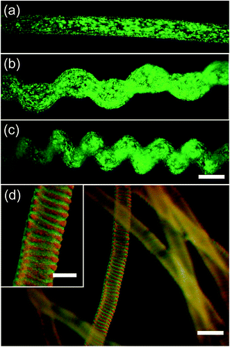
Fig. 5a–c show gelled alginate hydrogel microfibers with various morphologies (straight, folded, and coiled fibers, respectively). Fluorescent particles (yellow-green fluorescent carboxylate-modified microspheres, 0.2 μm, FluoSpheres) were added to aid visualization of the microfibers. Fig. 4d shows packed coiled tubular microfibers formed using a double coaxial microchannel to generate a core-annular flow with two colored sodium alginates (core: red, and shell: yellow-green fluorescent carboxylate-modified microspheres, 0.2 μm, FluoSpheres). The resulting tubular double-layered microfiber showed that mixing in the viscous inner thread was negligible. Similarly, microfibers with parallel (Janus) configuration were also fabricated using Y-junction microchannels (Fig. S4†). Further modification in channel geometry (e.g. bending) may allow even more complex patterned of viscous threads and hydrogel microfibers. This fabrication method could potentially be used to fabricate microfibers with improved physical properties,10,14 as well as cell scaffolds19–22 where circumferentially oriented directionality patterns are useful.
Acknowledgements
We thank Hiroaki Onoe for fruitful discussions and Shintaroh Iwanaga for help with viscosity measurements. This work was supported by the Takeuchi Biohybrid Innovation Project, Exploratory Research for Advanced Technology (ERATO), Japan Science and Technology (JST), Japan.References
- G. Barnes and R. Woodcock, Am. J. Phys., 1958, 26, 205–209 CrossRef
.
- L. Mahadevan, W. S. Ryu and A. D. T. Samuel, Nature, 1998, 392, 140 CrossRef CAS PubMed
.
- N. M. Ribe, Proc. R. Soc. London, Ser. A, 2004, 460, 3223–3239 CrossRef
.
- N. M. Ribe, M. Habibi and D. Bonn, Annu. Rev. Fluid Mech., 2012, 44, 249–266 CrossRef
.
- M. Habibi, Y. Rahmani, D. Bonn and N. M. Ribe, Phys. Rev. Lett., 2010, 104, 074301 CrossRef CAS
.
- T. Cubaud and T. G. Mason, Phys. Rev. Lett., 2006, 96, 114501 CrossRef
.
- T. Cubaud and T. G. Mason, Soft Matter, 2012, 8, 10573–10582 RSC
.
- T. Cubaud, B. M. Jose and S. Darvishi, Phys. Fluids, 2011, 23, 042002 CrossRef PubMed
.
- E. Kang, G. S. Jeong, Y. Y. Choi, K. H. Lee, A. Khademhosseini and S. H. Lee, Nat. Mater., 2011, 10, 877–883 CrossRef CAS PubMed
.
- D. Kiriya, R. Kawano, H. Onoe and S. Takeuchi, Angew. Chem., Int. Ed., 2012, 51, 7942–7947 CrossRef CAS PubMed
.
- M. Yamada, S. Sugaya, Y. Naganuma and M. Seki, Soft Matter, 2012, 8, 3122–3130 RSC
.
- H. Onoe, T. Okitsu, A. Itou, M. Kato-Negishi, R. Gojo, D. Kiriya, K. Sato, S. Miura, S. Iwanaga, K. Kuribayashi-Shigetomi, Y. T. Matsunaga, Y. Shimoyama and S. Takeuchi, Nat. Mater., 2013, 12, 584–590 CrossRef CAS PubMed
.
- J. K. Nunes, H. Constantin and H. A. Stone, Soft Matter, 2013, 9, 4227–4235 RSC
.
- K. M. Hakansson, A. B. Fall, F. Lundell, S. Yu, C. Krywka, S. V. Roth, G. Santoro, M. Kvick, L. Prahl Wittberg, L. Wagberg and L. D. Soderberg, Nat. Commun., 2014, 5, 4018 Search PubMed
.
- A. Y. Hsiao, T. Okitsu, H. Onoe, M. Kiyosawa, H. Teramae, S. Iwanaga, T. Kazama, T. Matsumoto and S. Takeuchi, PLoS One, 2015, 10, e0119010 Search PubMed
.
- T. Cubaud and T. G. Mason, New J. Phys., 2009, 11, 075029 CrossRef
.
- S. Chiu-Webster and J. R. Lister, J. Fluid Mech., 2006, 569, 89–111 CrossRef
.
- S. Darvishi and T. Cubaud, Soft Matter, 2012, 8, 10658–10668 RSC
.
- E. Kang, Y. Y. Choi, S. K. Chae, J. H. Moon, J. Y. Chang and S. H. Lee, Adv. Mater., 2012, 24, 4271–4277 CrossRef CAS PubMed
.
- M. A. Daniele, D. A. Boyd, A. A. Adams and F. S. Ligler, Adv. Healthcare Mater., 2014, 4, 11–28 CrossRef PubMed
.
- Y. Jun, E. Kang, S. Chae and S. H. Lee, Lab Chip, 2014, 14, 2145–2160 RSC
.
- H. Onoe and S. Takeuchi, Drug Discovery Today, 2014, 20, 236–246 CrossRef PubMed
.
Footnote |
| † Electronic supplementary information (ESI) available. See DOI: 10.1039/c5ra01037c |
| This journal is © The Royal Society of Chemistry 2015 |


