 Open Access Article
Creative Commons Attribution 3.0 Unported Licence
Synthesis of ammonia directly from wet nitrogen using a redox stable La0.75Sr0.25Cr0.5Fe0.5O3−δ–Ce0.8Gd0.18Ca0.02O2−δ composite cathode
Ibrahim A.
Amar
a,
Rong
Lan
a and
Shanwen
Tao
*ab
aDepartment of Chemical & Process Engineering, University of Strathclyde, Glasgow G1 1XJ, UK. E-mail: shanwen.tao@strath.ac.uk; Fax: +44 (0) 141 548 2539; Tel: +44 (0) 141 548 2361
bSchool of Engineering, University of Warwick, Coventry CV4 7AL, UK
First published on 23rd April 2015
Abstract
Ammonia was directly synthesised from wet nitrogen at an intermediate temperature (375–425 °C) based on the oxygen-ion conduction of the Ce0.8Gd0.18Ca0.02O2−δ–((Li/Na/K)2CO3) composite electrolyte. A redox stable perovskite-based catalyst, La0.75Sr0.25Cr0.5Fe0.5O3−δ (LSCrF), was synthesised via a combined EDTA–citrate complexing sol–gel process to be used as a component of the La0.75Sr0.25Cr0.5Fe0.5O3−δ–Ce0.8Gd0.18Ca0.02O2−δ composite cathode for ammonia synthesis. Ammonia formation was studied at 375, 400 and 425 °C and a maximum ammonia formation rate of 4.0 × 10⁻¹⁰ mol s−1 cm−2 with corresponding Faradaic efficiency of 3.87% was observed at 375 °C when the applied voltage was 1.4 V. This is much higher than 7.0 × 10⁻¹¹ mol s−1 cm−2 at 1.4 V and 400 °C when Cr-free Sr-doped LaFeO3−δ, La0.6Sr0.4FeO3−δ was used as the catalyst for the electrochemical synthesis of ammonia, indicating LSCrF is potentially a better catalyst. Ammonia was successfully synthesised using a redox stable cathode with higher formation rates at reduced temperature. Introduction of Cr3+ ions at the B-site of doped LaFeO3 improves both the chemical stability and catalytic activity for ammonia synthesis.
1. Introduction
Ammonia is the second most produced chemical in large quantities in the world. It is not only an end product but also an important intermediate in the manufacture of many chemicals including; urea, nitric acid, ammonium nitrate, ammonium sulphate and ammonium phosphate.1 In 2011, approximately 136 million metric tons of ammonia was produced of which ∼80% was consumed by the fertiliser industry.1,2Currently, ammonia is produced on a large-scale via the Haber–Bosch process which was developed in the early 1900s. This process suffers from many drawbacks including; the low ammonia conversion (10–15%), high energy consumption, operation at high temperature (∼500 °C) and high pressure (150–300 bar) and severe environmental pollution (CO2 emission).1 Therefore, to avoid the Haber processes thermodynamic limitations (limited conversion) and to reduce the CO2 emission, alternative ammonia synthesis approaches have been proposed. In 1996, Panagos et al.3 proposed a model process using a solid state proton conductor to overcome the thermodynamic constraints of the traditional ammonia synthesis process. In 1998, Marnellos and Stoukides4 confirmed the first experimental ammonia synthesis from its constituents (H2 and N2) at atmospheric pressure using an electrochemical cell based on the proton-conducting electrolyte SrCe0.95Yb0.05O3−δ (SCYb).4
In the literature, several solid state proton conductors have been used as electrolytes for synthesising ammonia electrochemically.5–10 In these mentioned reports, pure H2 was used as source of the required protons (H+) for ammonia synthesis. However, there are some problems associated with using H2 as one of the precursors including; the production, purification, storage and transportation of hydrogen.11,12 On other hand, water can be used as an ideal proton source. In 2009, Skodra and Stoukides13 reported the synthesis of ammonia for first time directly from H2O and N2 without the need for hydrogen production stage. In that study, either solid oxide protonic or oxygen ion conductors was used as an electrolyte and Ru-based catalyst was used as a working electrode (cathode). Ammonia was produced under atmospheric pressure with a maximum formation rate of ∼4 × 10⁻¹³ mol s−1 cm−2 at 650 °C at 2 V. Recently, ammonia has been synthesised directly from H2O and N2 using an electrolytic cell based on CoFe2O4–CGDC composite as a cathode and doped ceria–carbonate composite as O2− conducting electrolyte.14 In that study, the ammonia production rate of 6.5 × 10⁻¹¹ mol s−1 cm−2 was obtained at 400 °C and 1.6 V.
The principle electrochemical synthesis of ammonia from water and N2 based on oxide-ion (O2−) conducting electrolytes can be written as follows,13
At the cathode,
| 3H2O + N2 + 6e− → 3O2− + 2NH3 | (1) |
At the anode, the transported oxygen ions through the electrolyte will combine to form oxygen gas;
 | (2) |
The overall reaction will be;
 | (3) |
Under the circumstance, if wet nitrogen is fed in the cathode in a two chamber cell, when a dc voltage is applied to the cell, ammonia will be produced at the cathode, oxygen at the anode. However, water splitting reaction is another completing reaction at the cathode,
| H2O + 2e− → H2 + O2− | (4) |
The produced O2− ions will transport to the anode, releasing oxygen according to reaction (2). The overall reaction for water splitting reaction is,
| 2H2O → 2H2 + O2 | (5) |
Therefore the ammonia synthesis and water splitting processes are competing with each other. Both ammonia and hydrogen can be produced at the cathode, depending on the catalytic activity of the cathode catalysts. Very important, the produced hydrogen at the cathode may further reaction with the catalysts, causing degradation of catalytic activity. Therefore an ideal ammonia synthesis catalyst should be redox stable which can sustain the highly reducing atmosphere in the presence of hydrogen at high temperatures.
The perovskite-based oxides are of interest owing to their ease of synthesis, low manufacture cost, high thermal stability and good catalytic activity.15 These oxides have been used as electrodes in many applications such as solid oxide fuel cells (SOFCs),16–19 solid oxide steam electrolysis cells (SOECs)20–22 and electrochemical synthesis of ammonia.23–26 Tao and Irvine investigated the redox stability and catalytic properties of La0.75Sr0.25Cr0.5Fe0.5O3−δ (LSCrF).27 In that study, it was found out that LSCrF exhibited excellent catalytic activity for methane-reforming. LSCrF is a redox stable oxide with electronic conductivity of approximately 14.3 in air and 0.21 S cm−1 in 5% H2 at 900 °C.27 On the other hand, the industrial ammonia synthesis catalysts are mainly Fe-based composite. To use a Fe-containing perovskite as cathode catalysts for electrochemical synthesis of ammonia will be a good approach. Fe-containing perovskite oxides SmFe0.7Cu0.1Ni0.2O3−δ (SFCN), SmBaCuFeO5+δ (SBCF) have been reported as cathode for electrochemical synthesis of ammonia from N2 and H2 based on electrochemical cells using Nafion as the electrolyte.5,29,30 The highest observed ammonia formation rate was 1.13 × 10⁻⁸ mol s−1 cm−2 when SFCN was used as the cathode with an operating temperature of 80 °C.29 For high temperature cells, perovskite oxide Ba0.5Sr0.5Co0.8Fe0.2O3−δ combined with Ag–Pd film was used as cathode for electrochemical synthesis of ammonia from N2 and H2 and an ammonia formation rate of 4.1 × 10⁻⁹ mol s−1 cm−2 was observed at 530 °C for a cell based on BaCe0.85Y0.15O3−δ (BCY15) electrolyte.23 We also investigated the use of perovskite oxide La0.6Sr0.4Fe0.8Cu0.2O3−δ as the cathode and an ammonia formation rate of 5.39 × 10⁻⁹ mol s−1 cm−2 at 450 °C was observed.24 In a previous study, we reported that a maximum ammonia formation rate of 7.0 × 10⁻¹¹ mol s−1 cm−2 was observed at 400 °C and 1.4 V when La0.6Sr0.4FeO3−δ–Ce0.8Gd0.18Ca0.02O2−δ composite was used as the cathode.28 To the best of our knowledge, there is no report on the electrochemical synthesis of ammonia using LSCrF as the catalyst. Here, for the first time, we report the synthesis of ammonia directly wet N2 in an electrolytic cell using redox stable La0.75Sr0.25Cr0.5Fe0.5O3−δ–Ce0.8Gd0.18Ca0.02O2−δ (LSCrF–CGDC) composite as the cathode. Ce0.8Gd0.18Ca0.02O2−δ–((Li/Na/K)2CO3) composite was used as electrolyte using its oxygen-ion (O2−) conduction.
2. Experimental
2.1 Materials synthesis
La0.75Sr0.25Cr0.5Fe0.5O3−δ (LSCrF) catalyst was synthesised via a combined EDTA–citrate complexing sol–gel process. Lanthanum oxide (La2O3, Alfa Aesar, 99%), strontium nitrate (Sr(NO3)2, Alfa Aesar, 99%) and chromium nitrate nonahydrate (Cr(NO3)3·9H2O, Sigma Aldrich, 99%) iron nitrate nonahydrate (Fe(NO3)3·9H2O, Alfa Aesar, 98%) were used as starting materials. La2O3 was dissolved in diluted nitric acid to form lanthanum nitrate. Calculated amounts of Sr(NO3)2, Cr(NO3)3·9H2O and Fe(NO3)3·9H2O were dissolved in deionised water and then added to the lanthanum nitrate solution. Citric acid and EDTA (ethylenediaminetetraacetic acid) were then added as complexing agents with molar ratio of citric acid![[thin space (1/6-em)]](https://www.rsc.org/images/entities/char_2009.gif) :
:![[thin space (1/6-em)]](https://www.rsc.org/images/entities/char_2009.gif) EDTA
EDTA![[thin space (1/6-em)]](https://www.rsc.org/images/entities/char_2009.gif) :
:![[thin space (1/6-em)]](https://www.rsc.org/images/entities/char_2009.gif) metal cations of 1.5
metal cations of 1.5![[thin space (1/6-em)]](https://www.rsc.org/images/entities/char_2009.gif) :
:![[thin space (1/6-em)]](https://www.rsc.org/images/entities/char_2009.gif) 1
1![[thin space (1/6-em)]](https://www.rsc.org/images/entities/char_2009.gif) :
:![[thin space (1/6-em)]](https://www.rsc.org/images/entities/char_2009.gif) 1. NH3·H2O was added to the mixed solution to adjust the pH value to around 6. Under heating and stirring, the solution was evaporated on a hot-plate, and then gradually changed into a black sticky gel before complete drying. The as-prepared powder was ground and subsequently calcined in air at 1200 °C for 2 h with heating/cooling rates of 5 °C min−1 to obtain a pure phase of LSCrF catalyst without any carbon residue.
1. NH3·H2O was added to the mixed solution to adjust the pH value to around 6. Under heating and stirring, the solution was evaporated on a hot-plate, and then gradually changed into a black sticky gel before complete drying. The as-prepared powder was ground and subsequently calcined in air at 1200 °C for 2 h with heating/cooling rates of 5 °C min−1 to obtain a pure phase of LSCrF catalyst without any carbon residue.
Sm0.5Sr0.5CoO3−δ (SSCo) catalyst and Gd and Ca co-doped ceria Ce0.8Gd0.18Ca0.02O2−δ (CGDC) powders were also synthesised via a combined EDTA–citrate complexing sol–gel process as described elsewhere. The composite electrolyte was prepared by mixing CGDC and ternary carbonate ((Li/Na/K)2CO3) in weight ratio of 70![[thin space (1/6-em)]](https://www.rsc.org/images/entities/char_2009.gif) :
:![[thin space (1/6-em)]](https://www.rsc.org/images/entities/char_2009.gif) 30 as described elsewhere.14
30 as described elsewhere.14
2.2 Materials characterisation
X-ray diffraction (XRD) data were collected at room temperature using a Panalytical X'Pert Pro diffractometer with Ni-filtered CuKα radiation (λ = 1.5405 Å), using 40 kV and 40 mA, fitted with a X'Celerator detector. Absolute scans were recorded in the 2θ range 5–100°, with a step size of 0.0167°.The microstructures of the prepared catalyst and the cross-sectional area of the single cell were examined using a Hitachi SU6600 Scanning Electron Microscope (SEM).
Thermogravimetry and differential scanning calorimetry (TGA/DSC) analyses were performed using a Stanton Redcroft STA/TGH series STA 1500, operating through a Rheometric Scientific system interface controlled by the software RSI Orchestrator. The thermal behaviour of the perovskite based cathode (LSCrF) was investigated in N2 atmosphere from room temperature to 500 °C with a heating/cooling rate of 10 °C min−1.
2.3 Fabrication of the single cell for ammonia synthesis
A tri-layer single cell was fabricated by a cost-effective, one-step, dry-pressing method. The composite anode was prepared by mixing in a mortar SSCo, CGDC and a pore former (starch), with weight ratio of 70![[thin space (1/6-em)]](https://www.rsc.org/images/entities/char_2009.gif) :
:![[thin space (1/6-em)]](https://www.rsc.org/images/entities/char_2009.gif) 30
30![[thin space (1/6-em)]](https://www.rsc.org/images/entities/char_2009.gif) :
:![[thin space (1/6-em)]](https://www.rsc.org/images/entities/char_2009.gif) 15. The composite electrolyte consists of CGDC/(Li/Na/K)2CO3 (70
15. The composite electrolyte consists of CGDC/(Li/Na/K)2CO3 (70![[thin space (1/6-em)]](https://www.rsc.org/images/entities/char_2009.gif) :
:![[thin space (1/6-em)]](https://www.rsc.org/images/entities/char_2009.gif) 30 wt%). The composite cathode was prepared by mixing in a mortar LSCrF, CGDC and starch, with weight ratio of 70
30 wt%). The composite cathode was prepared by mixing in a mortar LSCrF, CGDC and starch, with weight ratio of 70![[thin space (1/6-em)]](https://www.rsc.org/images/entities/char_2009.gif) :
:![[thin space (1/6-em)]](https://www.rsc.org/images/entities/char_2009.gif) 30
30![[thin space (1/6-em)]](https://www.rsc.org/images/entities/char_2009.gif) :
:![[thin space (1/6-em)]](https://www.rsc.org/images/entities/char_2009.gif) 15. The composite anode, composite electrolyte and composite cathode were fed into the die, layer by layer, with the aid of a sieve to ensure uniform powder distribution, and then uniaxially pressed at pressure of 121 MPa. This freshly made green pellet was sintered in air at 700 °C for 2 h, at a rate of 2°C min−1 on heating/cooling. The active surface area of the cathode was 0.785 cm2. Silver paste was painted in a grid pattern on each electrode surface of the cell, as a current collector. Ag wires were used as output terminals for both electrodes.
15. The composite anode, composite electrolyte and composite cathode were fed into the die, layer by layer, with the aid of a sieve to ensure uniform powder distribution, and then uniaxially pressed at pressure of 121 MPa. This freshly made green pellet was sintered in air at 700 °C for 2 h, at a rate of 2°C min−1 on heating/cooling. The active surface area of the cathode was 0.785 cm2. Silver paste was painted in a grid pattern on each electrode surface of the cell, as a current collector. Ag wires were used as output terminals for both electrodes.
2.4 Ammonia synthesis
The fabricated single cells for ammonia synthesis were sealed into a self-designed double-chamber reactor, using ceramic paste (Aremco, Ceramabond 552). The electrolytic cell for ammonia was constructed as follows: air, SSCo–CGDC|CGDC–carbonate|LSCrF–CGDC, 3% H2O–N2. The cathode chamber was fed with 3% H2O–N2 (wet N2). The water vapour (3% H2O) was supplied to the cathode chamber by bubbling a N2 stream through a liquid water container, at 25 °C. The anode was exposed to air. The voltage was applied by a Solartron 1287A electrochemical interface controlled by software CorrWare/CorrView for automatic data collection. A constant voltage was applied and the ammonia synthesised at the cathode chamber was absorbed by 20 ml of diluted HCl (0.001 M) for 30 min. The concentration of NH4+ in the absorbed solution was analysed using ISE (Thermo Scientific Orion Star A214). The rate of ammonia formation was calculated using (6): | (6) |
AC impedance spectroscopy (IS) measurements were performed using a Schlumberger Solartron SI 1250 analyser, coupled with a SI 1287 Electrochemical Interface controlled by Z-plot/Z-view software. The AC impedance spectra were recorded over the frequency range 65 kHz to 0.01 Hz.
3. Results and discussion
3.1 XRD, SEM and thermal analysis
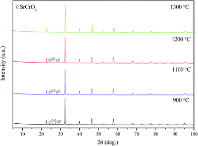
The XRD patterns of LSCrF powder calcined in air at different temperatures is shown in Fig. 1. As can be seen, a single-phase perovskite oxide of LSCrF was obtained when the corresponding ash was fired at 1300 °C for 2 h (Fig. 2c). Below 1300 °C, a small amount of second phase SrCrO4 (JCPDS card no. 35-734) was detected.32 The crystallite size of LSCrF is about 46.75 nm, estimated from Sherrer's formula. In order to investigate the compatibility between the CGDC and the perovskite oxide (LSCrF), the composite cathode (LSCrF–CGDC) was fired in air at 700 °C which is the sintering temperature for the single cell. As can be seen from Fig. 2, the XRD pattern of LSCrF–CGDC (Fig. 2c) displays only the corresponding peaks for CGDC (Fig. 2a) and LSCrF (Fig. 2b), no extra peaks were detected indicating that LSCrF is chemically compatible with CGDC at the single cell sintering temperature.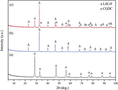 | ||
| Fig. 2 XRD patterns of (a) pure CGDC; (b) pure LSCrF; (c) LSCrF–CGDC composite cathode fired at 700 °C. | ||
The SEM micrograph of the LSCrF powder calcined in air at 1300 °C for 2 h is shown in Fig. 3a. As can be seen, the microstructure of LSCrF powder morphology is characterised by sphere-type particles with a slight agglomeration. Fig. 3b shows SEM micrograph of the cross-section view of single cell fabricated in air at 700 °C for 2 h. The cell composes of SSCo–CGDC composite as an anode, CGDC–(Li/Na/K)2CO3 as an electrolyte and LSCrF–CGDC composite as a cathode. The composite electrolyte is dense and adheres very well to the composite anode and the composite cathode, indicating good thermal compatibility.
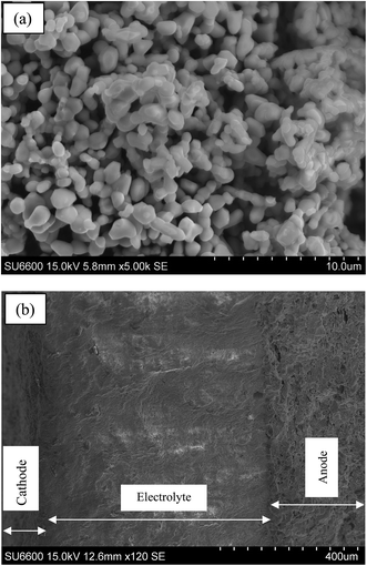 | ||
| Fig. 3 SEM images; (a) LSCrF calcined in air at 1300 °C: (b) cross-sectional area of the single cell before test. | ||
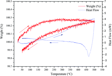
The thermal behaviour of LSCrF cathode was investigated under N2, as the cathode is exposed to this atmosphere during the ammonia synthesis. The TGA-DSC curves of LSCrF catalyst in N2 atmosphere from room temperature up to 500 °C are shown in Fig. 4. As can be seen, a slight (∼0.26%) weight gain was observed which is due to the buoyancy effect of air. The DSC curve shows no obvious thermal effects, indicating that there are no first order phase transitions. Sample decomposition or reaction between this perovskite-based cathode and N2 in the measured temperature range is unlikely. This suggests that LSCrF cathode is thermally stable in N2 within the measured temperature range.
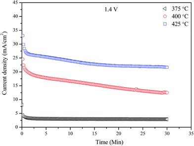
Fig. 5 shows the performance stabilities during the ammonia synthesis at different temperatures (375–425 °C) with an applied voltage of 1.4 V over a period of 30 min for the electrolytic cell based on LSCrF–CGDC composite cathode. As can be seen, the performance of the cell was stable at 375 °C but the current tends to increase at higher temperatures. In addition, it is obvious that the generated current densities increase significantly as the cell operating temperature increased and reached maximum values of 23.13 mA cm−2 at 425 °C for LSCrF–CGDC. This is due to the increased oxygen ions (O2−) conductivity at evaluated temperatures.
Fig. 6a shows the in situ AC impedance spectra under open circuit conditions at different temperatures (375–425 °C). Two depressed semicircles were observed. These data were fitted using the equivalent circuit shown in Fig. 6b. In this circuit, L represents an inductance that caused by the instrument and connection wires, Rs is the series resistance (Rs) including resistances of the electrolyte, electrode materials and the contact resistance at the electrode/electrolyte interface, the two components (R1CPE1) and (R2CPE2) in series are associated to the electrode processes at high and low frequency arcs respectively. R1 and R2 represent the polarisation resistance while CPE is a constant phase element. It can be also seen from Fig. 6a, with increasing the cell operating temperature, the Rs which is mainly related to the ohmic resistance of the electrolyte decreased significantly due to the melting of (Li, Na, K)2CO3 carbonates. In addition, the total polarisation resistance, Rp(R1 + R2) decreased significantly with increasing the operating temperature due to enhanced catalytic activity of the electrode at evaluated temperatures.
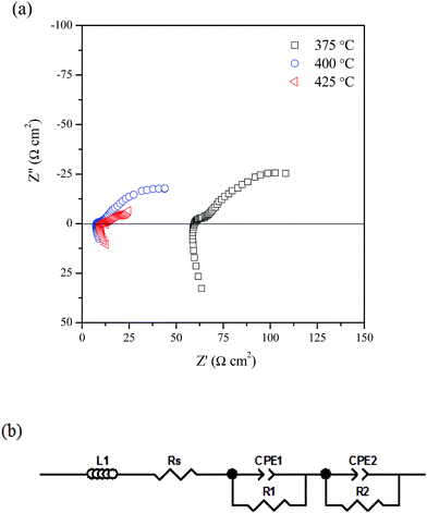 | ||
| Fig. 6 Impedance spectra under open circuit condition at 375–425 °C; (b) equivalent circuit for the impedance data. | ||
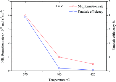
Fig. 7 shows the effect of the operating temperature on the ammonia formation rates was investigated under constant voltage (1.4 V) and varying the operating temperature from 375 to 425 °C. The ammonia production rates dropped significantly as the operating temperature increased from 375 to 425 °C. Furthermore, the maximum ammonia formation rate was 4.0 × 10⁻¹⁰ mol s−1 cm−2 at 375 °C at current density of 2.99 mA cm−2. The corresponding Faradaic efficiency was 3.87%.26 This low efficiency indicates that there is more than one process over the cathode surface and that the competitive hydrogen evolution reaction (HER) is the dominant one.33,34 This decrease in the ammonia formation rate with temperature, although the electrolyte ionic conductivity increases with temperature could be due the ammonia decomposition which becomes predominant at high temperature.35,36 Therefore the ammonia synthesis at higher temperature was not carried out. This experiment confirms that low temperature will benefit ammonia formation during electrochemical synthesis process. Therefore we fix the operating temperature to 375 °C in the following study.
3.2 Ammonia synthesis at different applied voltages at 375 °C
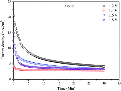
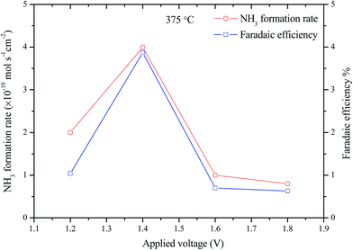
Fig. 8 shows the performance stabilities of the electrolytic cell at 375 °C and different applied voltages (1.2–1.8 V) over a period of 30 min. The initial current drop is due to the blocking effects of Li+, Na+, K+, HCO3−, CO32− ions which has been discussed in previous studies.26,37,38 These ions may form a positively charged layer at cathode/electrolyte interface, thus partially block the transfer of the O2− and resulting in low current densities. It should be noted that, highest current density happened at the lowest applied voltage, 1.2 V. This means that the oxygen ion conductivity of the CGDC–(Li/Na/K)2CO3 composite is related to the applied voltage. At higher applied voltage, the blocking effect of other ions are more significant leading to low O2− ionic conductivity, thus lower current. This also indicates that the O2− ionic conduction is not solely related to the CGDC phase, but also to the carbonates as well. Most likely, the O2− ions are transported through the oxide–carbonate interface.39 At a higher applied voltage, the driving force for transport of O2− ions is also higher. The two opposite effects will determine the current density. Therefore lowest current was observed at an applied voltage of 1.2 V (Fig. 8). The normalised final current density of the cell are 4.13, 2.88, 3.39 and 3.32 mA cm−2 respectively. The corresponding resistances are 0.29, 0.49, 0.47 and 0.54 kΩ cm2 respectively. The total resistance tends to increase at higher applied voltages, indirectly confirming the blocking effect. This phenomenon was also observed in electrochemical synthesis of ammonia when a H+/Li+/NH4+ mixed conducting membrane was used as the electrolyte.38The ammonia formation rates and corresponding Faradaic efficiency of the cell at 375 °C with different applied voltages are shown in Fig. 9. Significant increase in ammonia formation rate was observed when applied voltage increased from 1.2 to 1.4 V. When the electrolytic cell operated at a voltage higher than 1.4 V, the ammonia formation rate dropped significantly which could be due to the competitive adsorption between the N2 and H2 over the cathode surface.33,34 The maximum ammonia formation rate was 4.0 × 10⁻¹⁰ mol s−1 cm−2 at 1.4 V. An ammonia formation rate of 7.0 × 10⁻¹¹ mol s−1 cm−2 was observed for Cr-free Sr-doped LaFeO3−δ, La0.6Sr0.4FeO3−δ at 1.4 V and 400 °C.28 The ammonia formation rate is also higher than the 5 × 10⁻¹¹ and 1.23 × 10⁻¹⁰ mol s−1 cm−2 at 1.4 V and 400 °C when La0.6Sr0.4Fe0.8Cu0.2O3−δ and La0.8Cs0.2Fe0.8Ni0.2O3−δ was used as the cathode catalyst respectively for electrochemical synthesis of ammonia indicating LSCrF is potentially a better catalyst.26,40 The low ammonia production rate with the low current efficiencies (<4%) mean that there was more than one process occurring over the cathode surface and the hydrogen evolution is the dominant one.8,34 Introduction of Cr3+ ions at the B-site in doped LaFeO3 not only improve the stability in a reducing atmosphere, but also enhance the catalytic activity for ammonia synthesis. Cr3+ ions are potential promoter for ammonia synthesis catalysts based on Fe-containing perovskite oxides.
4. Conclusion
La0.75Sr0.25Cr0.5Fe0.5O3−δ (LSCrF) was synthesised via a combined EDTA–citrate complexing sol–gel process. The catalyst was characterised by X-ray diffraction (XRD), TGA-DSC analysis and scanning electron microscopy (SEM). A single-phase perovskite oxide (LSCrF) was obtained after firing the corresponding ash at 1300 °C for 2 h. LSCrF was thermally stable in N2 atmosphere up to 500 °C. A tri-layer electrolytic cell was successfully fabricated by a cost effective one-step dry-pressing and co-firing process. Ammonia was successfully synthesised directly from water and nitrogen (3% H2O–N2) in electrolytic cells based on cells fabricated from redox stable LSCrF–CGDC composite cathodes, CGDC–carbonate composite electrolyte and SSCo–CGDC composite anode. The maximum rate of ammonia formation was 4.0 × 10⁻¹⁰ mol s−1 cm−2 with a Faradaic efficiency of 3.87% at 375 °C at an applied voltage of 1.4 V. Compared to La0.8Cs0.2Fe0.8Ni0.2O3−δ catalyst, higher ammonia formation rate at reduced operating temperature was observed when La0.75Sr0.25Cr0.5Fe0.5O3−δ was used as the electrocatalyst. Low operating temperature will benefit ammonia formation. Introduction of Cr3+ ions at the B-site of doped LaFeO3 improves both the chemical stability and catalytic activity for ammonia synthesis.Acknowledgements
The authors gratefully thank EPSRC SuperGen XIV ‘Delivery of Sustainable Hydrogen’ project (Grant no. EP/G01244X/1) for funding. One of the authors (Ibrahim A. Amar) thanks The Libyan Cultural Affairs, London for the financial support of his study in UK.References
- M. Appl, Ammonia: principles and industrial practice, Wiley-VCH, Weinheim, Germany, 1999 Search PubMed.
- US G. Survey, Mineral Commodity Summaries, Geological Survey, 2012 Search PubMed.
- E. Panagos, I. Voudouris and M. Stoukides, Chem. Eng. Sci., 1996, 51, 3175–3180 CrossRef CAS.
- G. Marnellos and M. Stoukides, Science, 1998, 282, 98–100 CrossRef CAS PubMed.
- I. A. Amar, R. Lan, C. T. G. Petit and S. W. Tao, J. Solid State Electrochem., 2011, 15, 1845–1860 CrossRef CAS.
- S. Giddey, S. P. S. Badwal and A. Kulkarni, Int. J. Hydrogen Energy, 2013, 38, 14576–14594 CrossRef CAS.
- I. Garagounis, V. Kyriakou, A. Skodra, E. Vasileiou and M. Stoukides, Front. Energy Res., 2014, 2, 1–10 Search PubMed.
- R. Lan, J. T. Irvine and S. W. Tao, Sci. Rep., 2013, 3, 1145 Search PubMed.
- R. Lan, K. A. Alkhazmi, I. A. Amar and S. W. Tao, Appl. Catal., B, 2014, 152–153, 212–217 CrossRef CAS.
- S. Licht, B. Cui, B. Wang, F.-F. Li, J. Lau and S. Liu, Science, 2014, 345, 637–640 CrossRef CAS PubMed.
- K. Wang, R. Ran and Z. Shao, J. Power Sources, 2007, 170, 251–258 CrossRef CAS.
- S. McIntosh and R. J. Gorte, Chem. Rev., 2004, 104, 4845–4866 CrossRef CAS PubMed.
- A. Skodra and M. Stoukides, Solid State Ionics, 2009, 180, 1332–1336 CrossRef CAS.
- I. A. Amar, C. T. G. Petit, G. Mann, R. Lan, P. J. Skabara and S. W. Tao, Int. J. Hydrogen Energy, 2014, 39, 4322–4330 CrossRef CAS.
- G. Pecchi, M. Jiliberto, E. Delgado, L. Cadús and J. Fierro, J. Chem. Technol. Biotechnol., 2011, 86, 1067–1073 CrossRef CAS.
- C. Xia, W. Rauch, F. Chen and M. Liu, Solid State Ionics, 2002, 149, 11–19 CrossRef CAS.
- Z. Shao and S. M. Haile, Nature, 2004, 431, 170–173 CrossRef CAS PubMed.
- S. W. Tao and J. T. S. Irvine, Nat. Mater., 2003, 2, 320–323 CrossRef CAS PubMed.
- P. I. Cowin, C. T. Petit, R. Lan, J. T. Irvine and S. W. Tao, Adv. Energy Mater., 2011, 1, 314–332 CrossRef CAS.
- X. Yue and J. T. S. Irvine, Solid State Ionics, 2012, 225, 131–135 CrossRef CAS.
- Y. Gan, J. Zhang, Y. Li, S. Li, K. Xie and J. T. Irvine, J. Electrochem. Soc., 2012, 159, F763–F767 CrossRef CAS.
- Y. Li, Y. Wang, W. Doherty, K. Xie and Y. Wu, ACS Appl. Mater. Interfaces, 2013, 5, 8553–8562 CAS.
- W. Wang, X. Cao, W. Gao, F. Zhang, H. Wang and G. Ma, J. Membr. Sci., 2010, 360, 397–403 CrossRef CAS.
- I. A. Amar, C. T. G. Petit, L. Zhang, R. Lan, P. J. Skabara and S. W. Tao, Solid State Ionics, 2011, 201, 94–100 CrossRef CAS.
- J. Wang and R. Liu, Acta Chim. Sin., 2008, 66, 717–721 CAS.
- R. Lan, K. A. Alkhazmi, I. A. Amar and S. W. Tao, Electrochim. Acta, 2014, 123, 582–587 CrossRef CAS.
- S. W. Tao and J. T. Irvine, Chem. Mater., 2004, 16, 4116–4121 CrossRef CAS.
- I. A. Amar, C. T. G. Petit, R. Lan, G. Mann and S. W. Tao, RSC Adv., 2014, 4, 18749–18754 RSC.
- G. Xu, R. Liu and J. Wang, Sci. China, Ser. B: Chem., 2009, 52, 1171–1175 CrossRef CAS.
- Z. Zhang, Z. Zhong and R. Liu, J. Rare Earths, 2010, 28, 556–559 CrossRef CAS.
- I. A. Amar, R. Lan, C. T. G. Petit, V. Arrighi and S. W. Tao, Solid State Ionics, 2011, 182, 133–138 CrossRef CAS.
- I. Jung, D. Lee, S. O. Lee, D. Kim, J. Kim, S. H. Hyun and J. Moon, Ceram. Interfaces, 2013, 39, 9753–9758 CrossRef CAS.
- A. Sclafani, V. Augugliaro and M. Schiavello, J. Electrochem. Soc., 1983, 130, 734–736 CrossRef CAS.
- V. Kordali, G. Kyriacou and C. Lambrou, Chem. Commun., 2000, 1673–1674 RSC.
- C. Chen and G. Ma, J. Alloys Compd., 2009, 485, 69–72 CrossRef CAS.
- E. Perman and G. Atkinson, Proc. R. Soc. London, 1904, 74, 110–117 CrossRef.
- L. Fan, G. Zhang, M. Chen, C. Wang, J. Di and B. Zhu, Int. J. Electrochem. Sci., 2012, 7, 8420–8435 CAS.
- R. Lan and S. W. Tao, RSC Adv., 2013, 3, 18016–18021 RSC.
- L. Fan, C. Wang, M. Chen and B. Zhu, J. Power Sources, 2013, 234, 154–174 CrossRef CAS.
- I. A. Amar, R. Lan and S. Tao, J. Electrochem. Soc., 2014, 161, H350–H354 CrossRef CAS.
| This journal is © The Royal Society of Chemistry 2015 |

