Zhonglu Guoab,
Linggang Zhua,
Jian Zhoua and
Zhimei Sun*a
aSchool of Materials Science and Engineering, and Center for Integrated Computational Materials Engineering, International Research Institute for Multidisciplinary Science, Beihang University, Beijing 100191, China. E-mail: zmsun@buaa.edu.cn
bCollege of Materials, Xiamen University, Xiamen 361005, China
First published on 4th March 2015
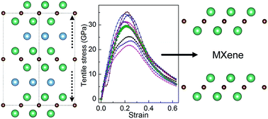
Two-dimensional transition metal carbides/nitrides Mn+1Xns labeled as MXenes derived from layered transition metal carbides/nitrides referred to as MAX phases attract increasing interest due to their promising applications as Li-ion battery anodes, hybrid electro-chemical capacitors and electronic devices. To predict the possibility of forming various MXenes, it is necessary to have a full understanding of the chemical bonding and mechanical properties of MAX phases. In this work, we investigated the chemical bonding changes of MAX phases in response to tensile and shear stresses by ab initio calculations using M2AlC (M = Ti, Zr, Hf, V, Nb, Ta, Cr, Mo and W) as examples. Our results show that the M2C layer is likely to separate from the Al layer during the tensile deformation, where the failure of M2AlC is characterized by an abrupt stretch of the M–Al bonds. While under shear deformation, the M2C and Al layers slip significantly relative to each other on the (0001) basal planes. It is found that the ideal strengths of M2AlC are determined by the weak coupling of the M2C and Al layers, closely related to the valence-electron concentration. Our results unravel the possibility as well as the microscopic mechanism of the fabrication of MXenes through mechanical exfoliation from MAX phases.
Many theoretical works have been done focusing on the mechanical properties of M2AlC compounds in the past decades.15,16,20–29 In our previous studies, we have investigated the elastic properties of nanolayered M2AlC/M2AlN,15,16,25,26 with M = Ti, Zr, Hf, V, Nb, Ta, Cr, Mo and W, by ab initio calculations. We have also classified the M2AlC phases into two groups by whether the bulk modulus of binary MC is conserved or changed after the incorporation of Al,16 which can be understood in terms of the coupling between the MC and Al layers. On the other hand, the M2AlC phases (M = Sc, Y, La, Ti, Zr, Hf, V, Nb, Ta, Cr, Mo, W) could also be classified into two groups based on the valence-electron concentration induced changes in C44.22 On the other hand, the elastic properties of MXenes have also been calculated recently.30 However, these works are mainly focused on elastic properties, which are the secondary derivative of the total energy with respect to a small strain. To gain a deeper understanding of the micro mechanism for the exfoliation of M2C from M2AlC that is achieved by the cleavage of M2C and Al layers, it is essential to investigate the mechanical properties under deformation, i.e. complete stress–strain relations, from which the first maximum stress is ideal strength.31–33 Ideal strength is the first derivative of total energy with respect to the critical point where instability occurs under deformation, which can be considered as the lowest stress required for cleavage or fracture of perfect crystal.34,35 Furthermore, the macroscopic mechanical properties can be interpreted by studying the atomic displacement and the chemical bonding changes at the microscopic scale when a large strain is applied. In this paper, we have calculated the stress–strain curves of M2AlC with M = Ti, Zr, Hf, V, Nb, Ta, Cr, Mo and W at a large strain and investigated the deformation mechanism by ab initio calculations. We have also discussed the relationship between the valence-electron concentration of M and the ideal strength of M2AlC.
For the layered hexagonal structure of M2AlC phases, the [0001] direction has the lowest strength,13,16 therefore tension along the [0001] direction of the unit cell was used to investigate the interlayer interactions and the overall strength of the compounds. For layered hexagonal ternary compounds, the activated slip systems were quite limited on the (0001) basal-plane. Furthermore, perfect dislocations on the (0001) basal planes were detected by transmission electron microscopy after a deformation at room temperature.43,44 To understand the micro-scale shear deformation mechanism of M2AlC, shearing along the (0001)[110] direction was studied. Supercell with 72 atoms was employed in the shear deformation, which has been tested large enough to avoid the periodic limit. To ensure that the material is under uniaxial tension or pure shear, the lattice vectors and internal atomic positions were simultaneously relaxed using a conjugate-gradient scheme until the Hellmann–Feynman stress tensor components orthogonal to the pre-set strain are less than 0.2 GPa.33,45 Then, the fully relaxed structures under deformation were used to calculate the variations of bonds length, lattice parameter, cohesive energy, DOS and ELF versus strains in the present work.
Finally, it is worth to address the van der Waals effect on the interlayers interactions during tension along the [0001] direction. For this purpose, we calculated the stress–strain curves for Ti2AlC and Nb2AlC by the DFT-D2 method which includes the van der Waals corrections.46 The results show that the van der Waals effect only slightly increases the absolute value of the ideal tensile stress for both Ti2AlC and Nb2AlC, but it does not change the relative trend of the ideal strengths and hence should not have any influence on the conclusion. Therefore, we do not include the van der Waals correction in the present results.
![]() | ||
Fig. 1 The schematic view of M2AlC under (a) the [0001] tension strain, (b) no-strain and (c) the (0001)[1![]() |
Fig. 2a shows the stress–strain relations for M2AlC under uniaxial tension along the [0001] direction. For all the considered compounds, the stress increases monotonically with increasing the applied strain until reaching a critical point, after which the stress starts to fall. The critical point at the strain–stress curve of M2AlC corresponds to a strain of larger than 20%, indicating good resistance to the tensile deformation, which is in good agreement with the experimental results.13 Since all these nine M2AlC compounds considered here show similar stress–strain curves, we use Nb2AlC as the model system to investigate the deformation mechanism under tensile strains. Fig. 2b displays the lattice parameters (c and a) and bond lengths versus the applied strain for Nb2AlC. As the tensile strain was applied along the [0001] direction, c increases monotonically with strain, while the lattice parameter a decreases slightly. On the other hand, from the initial state to the critical tensile strain, the change in the Nb–Al length with strain is relatively slow and the inter-layer Nb–Al bonds are stretched without breaking, resulting in a monotonic increase of the stress. While after the critical tensile strain, the slope of the curve is larger compared to that before the critical point, indicating that the change in the Nb–Al length with strain is faster and the Nb–Al bonds are finally stretched to be unstable, resulting in a monotonic decrease of the tensile stress. Finally, it is obviously seen that the uniaxial tension along the [0001] direction predominantly elongates the inter-layer Nb–Al bonds, while the stronger Nb–C bonds remain almost unchanged. Fig. 2b reveals variation of the cohesive energy of the relaxed unit cell under various tensile strains. The monotonically increase in cohesive energy with the applied strain is consistent with the gradual stretching of the Nb–Al bonds. It also indicates that extra energy is required to elongate or compress a chemical bond from its initial stable state.
![]() | ||
Fig. 2 (a) The calculated stress–strain curves of M2AlC, (b) the variations of lattice parameter (a, c) and the bond lengths (Nb–Al, Nb–C) of Nb2AlC, (c) the variations of cohesive energy of Nb2AlC under tensile strain along the [0001] direction. The lattice parameter and bond lengths are normalized by the equation of Vstrain/V0, where V0 and Vstrain represent the values in structures under zero and various strains, respectively. The positions of the labeled atoms (Nb2) can be found in Fig. 1. |
Further analysis on the electron localization functions (ELF)41 visualizes the chemical bonding changes as a series of tensile strains were applied. The topological analysis of ELF is a very useful tool for the determination of chemical bonding strength. To gain a directly observation of the bond variation and atom distortion during the tensile deformation, Fig. 3 displays the ELF contour plots projected on the (110) planes for Nb2AlC at various tensile strains (0, 10%, 20%, 28%, 35% and 49%). It is clearly seen in Fig. 3 that with increasing the engineering tensile strain, the Nb–C bond strength remains unchanged, while the Nb–Al bonds are weakened significantly, resulting in the electrons being localized at around Al atoms. All the other eight M2AlC compounds display similar characters during applying the tensile strain. Given the analysis above, the deformation mechanism of M2AlC under the uniaxial tensile strain along the [0001] direction can be concluded as the stretch and breaking of M–Al bonds, and finally the compounds are separated into Al and M2C layers. Meanwhile, though the anisotropy of chemical bonding of MAX phase has been commonly accepted, the present results directly verify the assertion and simulate the bonds variations under deformation with detailed calculations. Therefore, the ideal tensile strengths of M2AlC are determined by the coupling strength of M2C and Al layers. In other words, two dimensional M2Cs could be synthesized through mechanical exfoliation, if the external applied tensile stress could exceed the ideal tensile strength of M2AlC.
![]() | ||
Fig. 3 The ELF contour plots projected on the (11![]() |
Fig. 4 displays the total and projected densities of states (DOS) for the strain-free Nb2AlC and that under tensile strains of 10%, 28% and 49%. As seen in Fig. 4, for unstrained Nb2AlC, the Al 3p and Nb 4d states, as well as the C 2p and Nb 4d states are hybridized at the energies of ∼−1.5 eV and ∼−4 eV, respectively. With increasing the tensile strain, it is found that the Al 3p and Nb 4d states are significantly shifted towards the Fermi level and the quantitative number of total DOS at Fermi level correspondingly increases in Table 1, indicating the instability of the stretched Nb–Al bonds. Meanwhile, the hybridization of the Al 3p and Nb 4d states are much weaker compared with the initial states, suggesting that the Nb–Al bonds are softened and can finally be broken by tensile strain. However, the Nb–C bonds do not show any reduction, thus the Nb–C bonds remain stable under all the investigated tensile strains. These conclusions on bonding picture are in good agreement with the above analysis on the basis of ELF results.
![]() | ||
Fig. 4 The calculated total and partial density of states for Nb2AlC under the [0001] tensile strains of (a) 0, (b) 10%, (c) 28% and (d) 49%. |
Tensile strain | 0 | 10% | 28% | 49% |
Numbers of TDOS at EF | 3.64 | 4.41 | 4.78 | 5.68 |
In case of shear deformation of M2AlC, the stress–strain relations under pure shear strain along the (0001)[110] direction is illustrated in Fig. 5a. For all the 9 investigated compounds, the stresses reach the peak position of the curve at a shear strain of around 12%, and then decrease to zero when the strain is about 23%. Afterwards, the stresses go through a negative minimum and reach to about zero again at a strain of around 49%. To gain a full understanding of these interesting stress–strain curves of M2AlC along the (0001)[1
10] direction, we have plotted the bond length change of Nb2AlC under various shear strains in Fig. 5b. It is seen that when Nb2AlC is under shear deformation, Nb2–Al bond is stretched and softened gradually, while Nb1–Al is being compressed up to the critical strain of 12%, where the stress reaches the maximum. Above the critical strain, Nb1–Al bond is recovered to the initial bond length and Nb2–Al bond is completely broken at a strain of 23%, which leads to a large stress decrease to be about zero. The positive shear stresses during this shear stage (from 0 to 23%) are coincided with the increase of cohesive energy versus strains in Fig. 5c. With further increasing the shear strain (from 23% to 49%), the distance between Nb2 and Al atoms increases monotonously and the stresses undergo a negative minimum and reach to another zero again. Meanwhile, the cohesive energy decreases significantly, which could be used to interpret the negative values of stress, indicating that this shear deformation stage (from 23% to 49%) is energetically favorable. Finally, it is interesting to see in Fig. 5b that the Nb–C bond lengths remain nearly unchanged during the whole shear process, indicating that the Nb2C is stable under the investigated shear deformation.
To unravel the mechanism of shear deformation of M2AlC, the variation of crystal structure is also analyzed for the case of Nb2AlC. Fig. 6 illustrates the side view of crystal structure for Nb2AlC under the shear strains of 0, 23% and 49% to investigate the atom displacement during the shear deformation. For Nb2AlC at the zero-strain state (Fig. 6a), the labeled Al atom locates on the top left of Nb3 atom, where the Nb2–Al bond has the normal bond length. At a shear strain of 23%, the labeled Al atom slips to the position right above Nb3 atom (Fig. 6b), resulting in the distance between Nb2 and Al atoms increases significantly. Since Nb–C bonds remain stable during the shear deformation, this displacement mostly origins from the slipping between Al and the Nb2C layers. Meanwhile, due to the highest cohesive energy, the structure under the shear strain of 23% is unstable and could be considered as the middle state during the slip displacement of Al atoms. Hence with further increasing the shear strain to be around 49%, the labeled Al atom slips to the top right of Nb3 atom in Fig. 6c and the structure reaches to a stable state, corresponding to a accomplishment of a one-atom-step relatively displacement between Al and Nb2C layer. The present simulated slipping between Al and Nb2C layers is consistent with the experimentally observed perfect dislocations on the (0001) basal planes by transmission electron microscopy after deformation at room-temperature.43,44 In a word, the shear deformation process of M2AlC can be described as the relative slipping between the Al and M2C layers on the (0001) basal planes.
![]() | ||
Fig. 6 The side view of crystal structures for Nb2AlC under the (0001)[1![]() |
The first maximum in a tensile (shear) stress–strain curve is defined as the ideal tensile (shear) strength. As seen in Fig. 7, for the 9 individual compounds, a general rule can be concluded that the ideal tensile strength increases with the valence electron concentration, i.e., elements M in group IVB leads to the lowest strength while those in group VIB are the strongest when they form the compound M2AlC. However, the variance trend of the ideal shear strength is relatively complex, and the strength of the M2AlC containing elements in group IVB is quite small considering the downward curve from group VB to group VIB. Apparently, both the tensile and shear strength of the compound is very sensitive to the valance electron concentration.
![]() | ||
Fig. 7 The calculated ideal strengths and the ratio of tensile to shear strength for M2AlC (M = Ti, Zr, Hf, V, Nb, Ta, Cr, Mo and W). |
To all the considered M2AlC phases, their ideal tensile strengths are much larger than the ideal shear strength as can be seen in Fig. 7. Meanwhile, the corresponding critical points in tensile deformation are all much larger compared to those in shear deformation. The crack formation needs a corresponding local tensile stress, which is in the direction perpendicular to the cleavage plane and is larger than the ideal tensile strength. Therefore, for M2AlC, the dislocation nucleation after loading a force larger than the ideal shear stress will be activated before crack formation which needs a force larger than the ideal tensile stress. This means that 2-D M2Cs are much easier to obtain through shear rather than tensile deformation. According to the black solid line in Fig. 7, it is expected that producing 2-D M2Cs is much more easily when M is an element from group IVB and VIB than that from group VB. Finally, among the nine investigated compounds, it can be predicted that two dimensional W2C and Zr2C are the relative easy to obtain because of their low shear strength and high ratio of tensile/shear strength.
This journal is © The Royal Society of Chemistry 2015 |