
Hydrothermal synthesis of Mn-doped CdS hollow sphere nanocomposites as efficient visible-light driven photocatalysts
Chunyan Zhangab,
Jiasheng Laic and
Juncheng Hu*a
aKey Laboratory of Catalysis and Materials Science of the State Ethnic Affairs Commission & Ministry of Education, South-Central University for Nationalities, Wuhan 430074, PR China. E-mail: junchenghuhu@hotmail.com; Tel: +86 27 67841302
bDepartment of Chemistry and Life Science, Liuzhou Teachers College, Liuzhou 545004, PR China
cDepartment of Physics and Information Science, Liuzhou Teachers College, Liuzhou 545004, PR China
First published on 6th January 2015
Abstract
A series of Mn-doped CdS hollow sphere photocatalysts has been directly synthesized by a simple and facile hydrothermal route for the first time. It was demonstrated that GSH acts as the S source and a gas bubble-template in this process. The products were characterized by XRD, SEM, TEM, HRTEM, XPS, and UV-vis spectroscopy. The as-prepared CdS and Mn-doped CdS hollow spheres all showed much higher activity than P25 under visible light (λ > 420 nm) irradiation. Among them, the 2.0 mol% Mn-doped CdS sample exhibited the highest photoactivity for the removal of organic pollutant RhB, and about 99.2% MO was decomposed after 50 min of visible light irradiation. Moreover, this catalyst also showed good stability, and after four cycles, the degradation efficiency still remained at 85%. The excellent photoactivity of the as-prepared Mn-doped CdS hollow spheres could be attributed to the synergistic effects of its appropriate band-gap structure and the special porous spherical morphology. The unique hollow sphere structure may favor the harvesting of excited light due to its special multiple scattering effect within the interior space, and the doping of Mn2+ may facilitate the generation of photoinduced electrons and hole pairs, and inhibit their recombination rate by acting as temporary trapping sites. This material may have great application potentials in environmental remediation and energy harvesting.
1. Introduction
Solar energy, due to its distinct advantage of being clean, accessible and inexhaustible,1 is being intensively researched, especially the visible light portion which accounts for 43% of the solar energy and is attracting increasing attention.2 Recently, the development of photocatalysts with high visible-light activities has become a challenging and interesting topic. These photocatalysts can utilize abundant solar energy and water resources in nature to solve many related problems, such as organic pollutant degradation and H2 production from water splitting.3–5 The development of photocatalysts has become a challenging and interesting topic of research. Various approaches have been developed to enhance the activity and extend the response of photocatalysts to the visible light region, such as controlling the size and shape of nanocrystals. Because of their high light-harvesting efficiency, fast mobility of charge carriers, and superior catalytic activity,6,7 hollow structured materials have been recognized as one type of promising material for applications in the field of photocatalytic processes. Luo et al.8 have prepared the general strategy for the one-pot synthesis of metal sulfide hollow spheres. On the other hand, doping metallic (Pt, Au and Ag, etc.) and nonmetallic (C, N and F, etc.) elements into conventional photocatalysts to decrease the band gap is a very good choice.9–15CdS, as an important II–VI group semiconductor material and a well-known visible-light-sensitive material,16 with a band-gap of 2.42 eV, has attracted considerable attention for the conversion of solar energy into chemical energy in recent years. Lee and Shen17 have reported types of CdS with various structures such as flower-like nanostructures, tetrapod-like nanorods and long branched NPs. However, the low separation efficiency of photogenerated electrons and holes and the fact that they are easily corroded make it unfavorable for wide applications in environmental remediation and solar conversion.18,19 Recently, many studies attempting to improve CdS photocatalytic performance focus on structural designs or surface modifications,20–25 such as nanowires, nanobelts, nanorods, and nanospheres. But these were not satisfying the need to increase both the photoactivity and the stability.26–29 Metal ion doping (such as Mn, Co, Fe, Ni, etc.) is demonstrated to be an effective means of controlling the band gap and absorption properties. Luo et al.30 have prepared a one-pot synthesis of CdS and Ni-doped CdS hollow spheres. The optical properties of bulk II–VI semiconductors containing manganese are essentially modified by electronic transitions within the half-filled 3d shell of the Mn2+ ions.31 Doping Mn2+ can alter the charge separation and recombination dynamics by creating electronic states in the midgap region, which is in favor of the improvement of the power conversion efficiency.32 Yan et al. have prepared triangular Mn-doped CdS nanowires33 and Cheng et al. have prepared single-crystal Mn2+-doped CdS nanowires.34 Mn2+ has been the most extensively studied luminescence activator in II–VI semiconductors. Mn-doped CdS NPs are interesting because Mn2+ ions provide good traps for the excited electrons, which gives rise to their potential use in nonlinear optics, electronic and optoelectronic devices. These exciting achievements motivated us to investigate Mn2+-doped CdS hollow spheres. Herein, we report a simple template-free hydrothermal method to prepare Mn-doped CdS hollow spheres using the biomolecule L-glutathione reduced (GSH) as the sulfur source and the bubble source. A large-scale amount of uniformed and well dispersed Mn-doped CdS hollow spheres were obtained without traditional tedious and intricate template removal procedures. This one-step route provides both the expected hollow structure and the Mn2+ doping. In addition, we experimentally demonstrate that the as-prepared Mn-doped CdS hollow spheres have an enhanced photocatalytic activity and improved durability for organic pollutant removal. The possible influential factors for the activity and stability are also discussed in detail.
2. Experimental details
2.1 Materials
Manganese acetate tetrahydrate (Mn(CH3COO)2·4H2O) was purchased from Sinopharm Chemical Reagent Co, Ltd (Shanghai, China); GSH (C6H12N2O4S2) and cadmium nitrate tetrahydrate (Cd(NO3)2·4H2O) were purchased from Aladdin. All chemicals used in the experiments were of analytical grade and were used without further purification.2.2 Synthesis of Mn-doped CdS
In a typical preparation, 0.825 mmol of GSH, and appropriate molar ratios of Cd(NO3)2·4H2O and Mn(CH3COO)2·4H2O, with the total mole number of Cd2+ and Mn2+ ions being 0.825 mmol, were dissolved in a mixed solution with 80.0 mL of deionized water. The Mn-doping concentration was designed to be 1.0, 2.0, 3.5, and 5.0 mol% (denoted as X mol% Mn-doped CdS), which was the molar ratio of the theoretical yield. After being continuously stirred for 1 h, the clear solution was transferred into a stainless steel vessel (Teflon cups with inner volumes of 100 mL), which was heated and maintained at 180 °C for 5 h and then cooled to room temperature naturally. The products were obtained using suction filtration, washed with de-ionized water and anhydrous ethanol alternately, and then dried at 60 °C overnight in an oven. Through varying the molar percentage of Mn2+ in the solutions, a series of Mn-doped CdS hollow spheres with different compositions were obtained.2.3 Characterization
The structure and phase of the samples were characterized using power X-ray diffraction (XRD) employing a scanning rate of 0.05° s−1 in the 2θ range from 10° to 80°, in a Bruker D8 Advance using monochromatized Cu Kα = 1.5404 Å. The microstructure and composition sizes were observed using transmission electron microscopy (TEM) and high-resolution transmission electron microscopy (HRTEM) with a Tecnai G20 microscope operating at an accelerating voltage of 200 kV, and with an energy-dispersive X-ray spectrometer (EDS) performing at 300 kV, respectively. The specimens for the TEM and HRTEM measurements were prepared by spreading a droplet of an ethanol suspension onto copper grids coated with perforated carbon films, and allowing them to dry in air. Scanning electron micrographs (SEM) were obtained with a SU8000 field-emission scanning electron microscope (FESEM, Hitachi, Japan) at an accelerating voltage of 15 kV. The surface composition of the catalysts was analyzed using X-ray photoelectron spectroscopy (XPS) which was equipped with a VG Multilab 2000 (VG Inc.) photoelectron spectrometer using monochromatic Al Kα radiation under vacuum at 2 × 10⁻⁶ Pa. All the binding energies were referenced to the C1s peak at 284.8 eV of the surface adventitious carbon. UV-vis diffuse reflectance spectra (DRS) were collected using a Shimadzu UV-2450 spectrophotometer from 200 to 800 nm using BaSO4 as the background. Reactive brilliant rhodamine-B (RhB) and methyl orange (MO) were chosen as the simulated pollutants to evaluate the photocatalytic activities of the as-prepared Mn-doped CdS hollow spheres. The catalytic mechanism and durability of the photocatalyst were also discussed.2.4 Photocatalytic activities and durability measurements
The photocatalytic activity of the sample was evaluated by the degradation of dyes RhB (50 mL, 1 × 10⁻⁵ mol L−1) and MO (50 mL, 10 mg L−1) under simulated visible-light (equipped with a 420 nm cutoff filter) irradiation by a 350 W Xe lamp with 32.86 lm W−1 luminous efficiency. In each experiment, 50 mg of the photocatalyst and 50 mL of an aqueous solution of RhB or MO were added into a flask, and the suspension underwent ultrasonic treatment for 10 min and was stirred for 1 h in the dark in order to reach the adsorption–desorption equilibrium at room temperature. The reaction was ensured to be at room temperature and the interference of the infrared radiation was reduced by passing through condensate water. At given time intervals, 3 mL of the liquid was sampled and then filtered to remove the catalyst particles for analysis. The filtrates were finally analyzed using a UV-vis spectrophotometer (UV-2450).In order to test the Mn-doped CdS hollow spheres’ durability, four cycles of photocatalytic measurements were employed by using 2.0 mol% Mn-doped CdS hollow spheres as representative samples. The photocatalyst was separated from the aqueous solution after each series of reactions. The filtered catalyst was washed with anhydrous ethanol and reused in the subsequent recycling experiment. After the experiment, the XRD spectrum of the final catalyst was also detected.
2.5 Analysis of hydroxyl radicals (˙OH)
The formation of ˙OH on the surface of the UV and visible illuminated samples was detected by a photoluminescence (PL) method using coumarin as a probe molecule. Coumarin can readily react with ˙OH to produce the highly fluorescent product, 7-hydroxycoumarin (7HC) (umbelliferone).35 The experimental procedure was similar to the measurement of the photocatalytic activity. In a typical process, 2.0 mol% Mn-doped CdS (50 mg) hollow spheres and coumarin (50 mL, 5.0 × 10⁻⁴ mol L−1) underwent ultrasonic treatment for 10 min and magnetic stirring for 1 h under dark conditions. Then, the mixture was irradiated under visible-light (λ > 420 nm). At given time intervals, 3 mL of the liquid was sampled and then filtered to remove the catalyst particles for measuring the increase in the PL intensity around 445 nm excited by 332 nm light.3. Results and discussion
3.1 Microstructure characterizations
XRD measurements were employed to investigate the phase and structure of the CdS and Mn-doped CdS samples. As shown in Fig. 1, these samples show similar line types, and all can be assigned to the hexagonal CdS with six characteristic diffraction peaks according to the standard JCPDS card (no. 77-2306). As no signals related to manganese or other impurities were detected in these spectra, it can be concluded that the doping of Mn2+ has little effect on the crystalline phase of CdS. The possible reason for this may result from the low dosage of Mn2+. However, with increasing Mn2+ content in the precursors, the peak intensity of these samples became gradually stronger, suggesting that these samples tend to be well crystallized.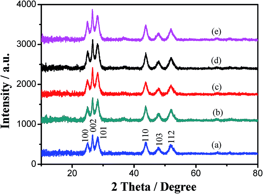 | ||
| Fig. 1 XRD patterns of (a) CdS, (b) 1.0 mol% Mn-doped CdS, (c) 2.0 mol% Mn-doped CdS, (d) 3.5 mol% Mn-doped CdS, (e) 5.0 mol% Mn-doped CdS. | ||
The morphology of the Mn-doped CdS hollow spheres and microspheres was studied by SEM and TEM. Fig. 2 shows the SEM and TEM images of 2.0 mol% Mn-doped CdS hollow spheres with different magnifications and the corresponding HRTEM image. Fig. 2(a) shows these microspheres with average diameters of about 300–600 nm, in which it is obvious that the surface of the spheres is coarse. From the broken sphere in Fig. 2(b), we can clearly see that the spheres have a typical hollow interior structure; it can be further clearly observed that the thickness of the wall of the broken hollow sphere is about 60 nm, indicating the thickness of the hollow spheres. In Fig. 2(c), a clear contrast between the dark edge and the pale center can be observed, which confirms that all the spheres have a hollow interior again. Fig. 2(a)–(c) indicates that these rough shells are constructed of loosely packed fine nanoparticles. These nanoparticles which accumulated to form the spheres, as building blocks for the spheres, can produce inherent porosity. These inherent apertures create numerous nanoscale channels for chemical moieties travelling between the interior cavity and the exterior space, which make the hollow spheres particularly suitable for further studies in adsorption and catalytic applications.8 Fig. 2(d) shows the corresponding high resolution TEM image; it shows clear lattice fringes, which allow for the identification of crystallographic spacing. The corresponding fast Fourier transform (FFT) pattern is shown in the inset of Fig. 2(d). As shown in Fig. 2(d), the crystallographic spacings of the 2.0 mol% Mn-doped CdS hollow spheres estimated from the HRTEM image are about 0.3582, 0.3357 and 0.3160 nm, which respectively correspond to the (100) (002) and (101) faces of hexagonal CdS. These results are consistent with the XRD analysis.
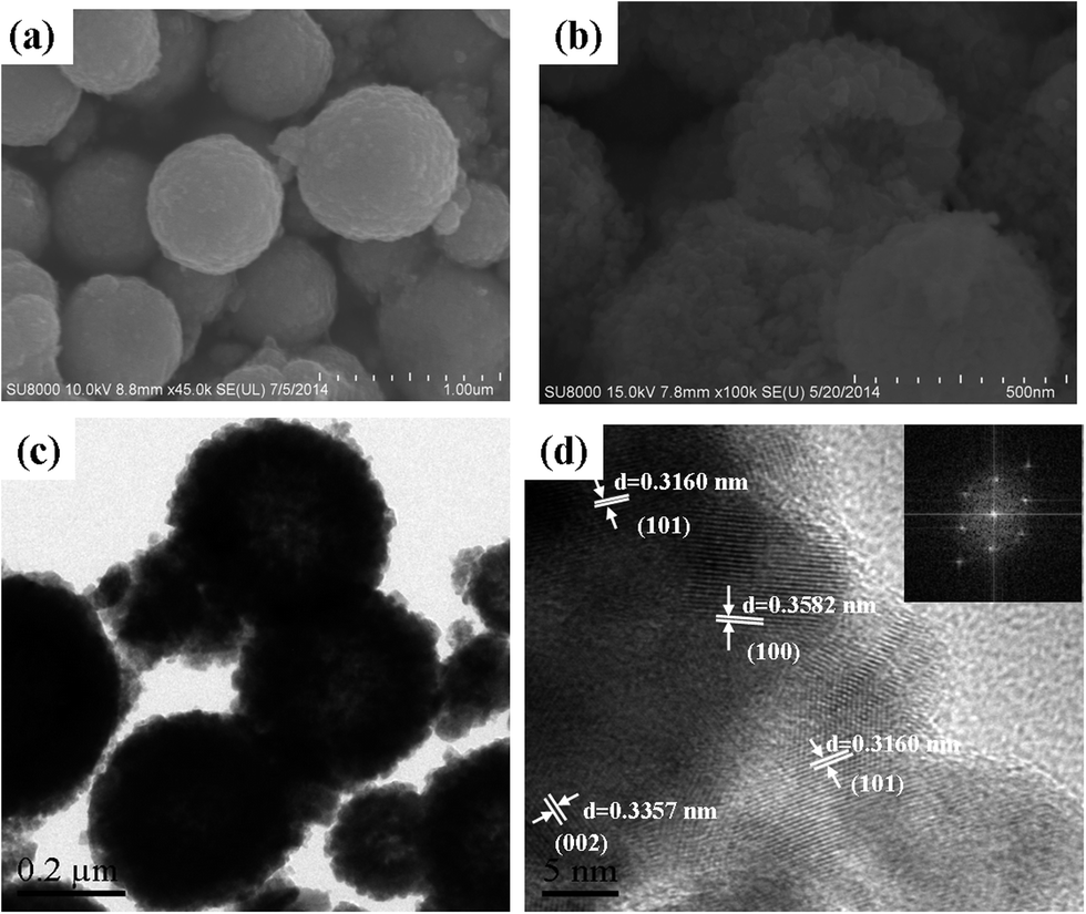 | ||
| Fig. 2 (a) and (b) SEM images, (c) TEM image and (d) the corresponding HRTEM image of 2.0 mol% Mn-doped CdS. | ||
Fig. 3 shows the TEM image of Mn-doped CdS with different Mn2+ doping concentrations. In all of the images of Fig. 3, the edges of these spheres are darker than their centers, which clearly reveals the natural hollow characteristic of these spheres, and indicates that the hollow structures can be generated in different Mn2+ doping concentrations. No significant difference in the size and thickness of the spheres is observed, even when the Mn2+ concentration was increased to 5 mol%, but fewer nanorods appeared at the edges of the spheres. These TEM images show the gradual development of the morphology following the increase of the Mn2+ concentration.
 | ||
| Fig. 3 TEM image of (a) CdS, (b) 1.0 mol% Mn-doped CdS, (c) 3.5 mol% Mn-doped CdS and (d) 5 mol% Mn-doped CdS. | ||
In an effort to gain further insight into the surfaces of the samples, pure CdS, and 2.0 and 5.0 mol% Mn-doped CdS samples were investigated by XPS. Because of the low doping concentrations, the signals of Mn 2p are very weak and it is difficult to detect. Fig. 4 provides information on the binding energies and intensities of the surface element S 2p of CdS and 2.0 and 5.0 mol% Mn-doped CdS. Compared with pure CdS, it can be found that the position of the peak shifts to a higher energy as the concentration of Mn2+ increases. This may be because some Cd2+ was replaced by Mn2+ in the CdS lattice and formed Cd–S–Mn bonds in the Mn-doped CdS samples. The difference in electronegativity (χ) between Cd (χp = 1.69), S (χp = 2.56) and Mn (χp = 1.55) results in a higher electron cloud density of S atoms, thus the binding energy of S 2p (161.36 and 161.58 eV for 2.0 and 5.0 mol% Mn-doped CdS, respectively) increases compared to pure CdS (161.34 eV). The asymmetric band of S 2p of the Mn-doped CdS samples can be fitted to two peaks; the peaks at about 161.09 and 161.30 eV can be assigned to the S atoms bonded to the Cd atoms. Similarly, the peaks at about 162.14 and 162.38 eV, which can be assigned to the S atoms bonded to the Mn atoms, are mainly due to the partial substitution of Cd2+ by Mn2+ in the CdS lattice.
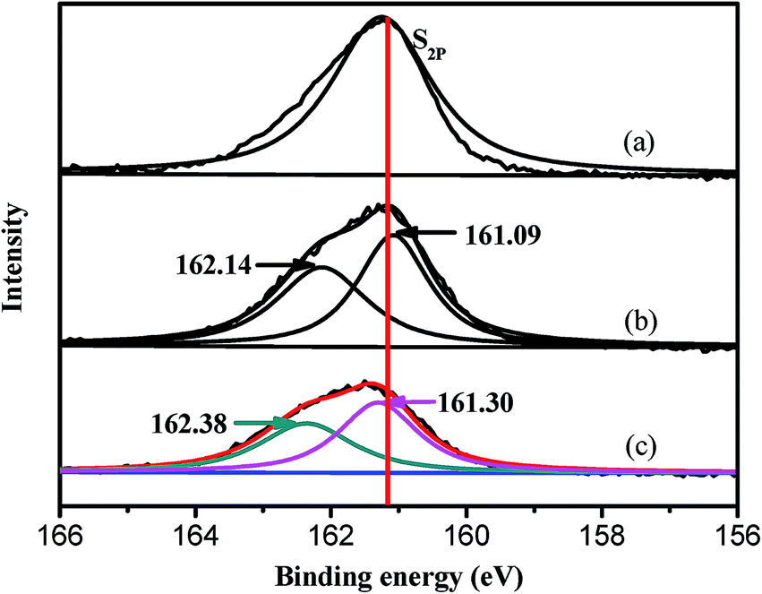 | ||
| Fig. 4 XPS results of S 2p of (a) CdS, (b) 2.0 mol%, and (c) 5.0 mol% Mn-doped CdS. | ||
UV-vis diffuse reflectance spectra (DRS) were measured to determine the optical properties of the un-doped and Mn-doped CdS hollow spheres. As shown in Fig. 5, all the samples have strong absorption in the visible-light region and these can be assigned to the intrinsic band gap absorption of CdS. The direct band gap values of the un-doped and Mn-doped CdS hollow sphere samples were estimated from the (Ahν)2 versus photon energy (hν) plot as shown in the inset of Fig. 5, where A, h and ν are the absorbance value, Planck constant and light frequency, respectively. After comparison, a slight blue shift is observed in the samples doped with Mn. This slight blue shift in the absorption edge is the outcome of the quantum confinement effect. This effect is due to the increase of nucleation rate with an increase in doping concentration.36 The band gap of CdS (2.30 eV) is lower than that of all the Mn-doped CdS hollow spheres (2.38, 2.36 and 2.32 eV). This indicates that the introduction of Mn2+ has a significant effect on the optical property of light absorption for the as-prepared Mn-doped CdS hollow spheres.
 | ||
| Fig. 5 UV-vis DRS of (a) CdS, (b) 2.0 mol% Mn-doped CdS, (c) 1.0 mol% Mn-doped CdS, and (d) 3.5 mol% Mn-doped CdS. The inset is the band gap evaluation from the plots of (Ahν)2 versus photon energy (hν). | ||
3.2 Photocatalytic properties of Mn-doped CdS
To demonstrate the potential applicability of the Mn-doped CdS hollow spheres, the photocatalytic degradation of dye RhB under visible light irradiation (λ > 420 nm) has been chosen as a model reaction to evaluate the photocatalytic activity of the prepared samples (Fig. 6). For reference, commercial product Degussa P25 and commercial CdS were also investigated under the same experimental conditions. As can be seen from Fig. 6, only a negligible activity is detected when the catalyst is not present. Both the CdS and Mn-doped CdS hollow spheres are much more superior to those of the commercial CdS, indicating the advantage of the hollow structure. The unique hollow structure of the Mn-doped CdS hollow spheres enables both the outer and inner surfaces of the catalyst to come into contact with the RhB molecules, provides more active sites that can interact, and allows multiple reflections of visible light within the interior cavities to promote the light-harvesting efficiency.37,38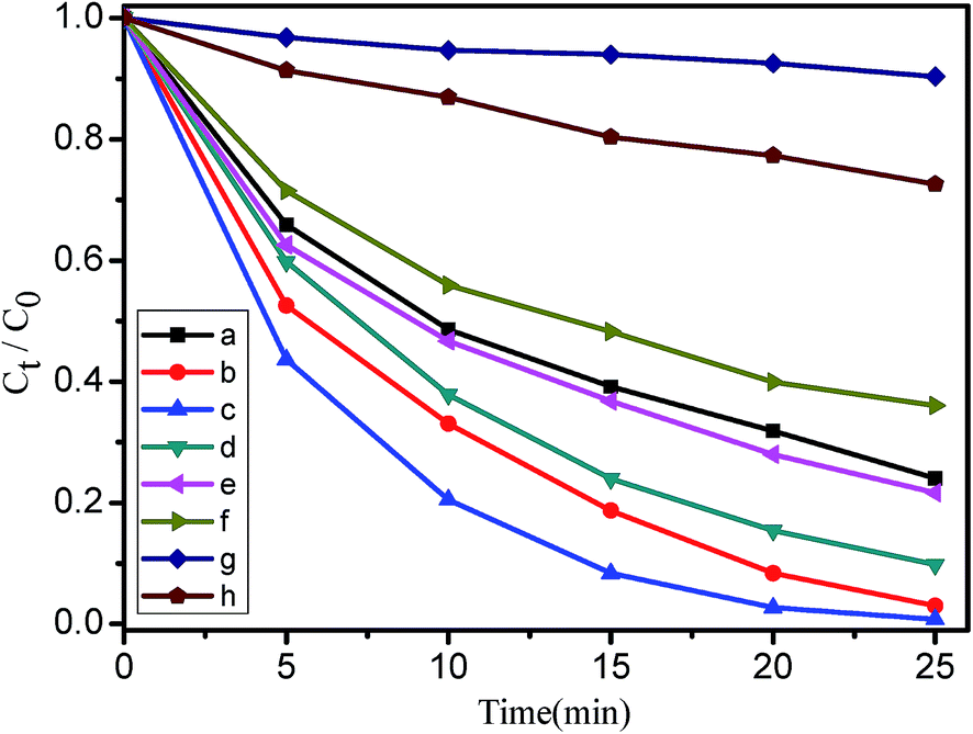 | ||
| Fig. 6 Photocatalytic degradation curves of RhB under visible light (λ > 420 nm) irradiation over (a) CdS hollow spheres, (b) 1.0 mol% Mn-doped CdS, (c) 2.0 mol% Mn-doped CdS, (d) 3.5 mol% Mn-doped CdS, (e) 5.0 mol% Mn-doped CdS, (f) Degussa P25, (g) catalyst-free, (h) commercial CdS. | ||
It can be found that all the Mn-doped CdS hollow spheres show more enhanced activity than that of the un-doped CdS hollow spheres. It is possible that the Mn2+ doping can provide them with intriguing properties inherited from the synergetic effect. We find that the activity of the Mn-doped CdS hollow spheres is not enhanced linearly with an increase in the Mn2+ content. This can be partly attributed to the relatively high doping concentrations of Mn2+, which might cause a reduced adsorption of RhB and become the recombination center of the photogenerated carriers, resulting in a decrease of the photocatalytic efficiency.39
It is also found that the 2.0 mol% Mn-doped CdS hollow spheres demonstrated the highest activity in the series of Mn-doped CdS photocatalysts. After 25 min of visible light irradiation, the amount of RhB remaining is as low as 0.3% and the degradation ratio is 99.73%, which indicates that Mn-doped CdS has a higher photocatalytic activity than Ni-doped CdS for RhB degradation.30 Comparing the reaction rate constants (k), we find that the RhB removal rate of the 2.0 mol% Mn-doped CdS hollow sphere (k = 0.1915) is about 5 times higher than that of the CdS hollow sphere (k = 0.0399). Therefore, it is believed that the right doping amount of Mn2+ contributed to the enhanced activity of the CdS hollow sphere. This can be attributed to more efficient light harvesting by the special structure and the effective separation of photogenerated carriers affected by optimal Mn2+ doping. Fig. 7 shows the temporal evolution of the absorption spectra of an RhB aqueous solution (the initial concentration is 1.0 × 10⁻⁵ M, 50 mL) in the presence of 50 mg 2.0 mol% Mn-doped CdS hollow spheres under visible light (λ > 420 nm) irradiation. After 25 min of irradiation, the maximum absorption band of the solution gradually shifted from 553.5 to 496 nm, which indicates that the de-ethylation process, instead of the decomposition of the conjugated chromophore structure, is the dominant process,40 and the color of the RhB aqueous solution changed from pink to colourless. Meanwhile, the absorption band gradually decreased, which indicates that the ethyl groups of RhB were removed during irradiation.41–43 For a further investigation of the photodegradation of RhB, the total organic carbon (TOC) removal in the corresponding solutions at different exposure times were detected, as shown in the inset of Fig. 7. With the extension of irradiation time, the concentration of organic carbon decreased steadily, indicating that the RhB dye can not only be discoloured but also degraded over Mn-doped CdS. It can be seen that the TOC removal efficiency increases to 52.9% for RhB after 25 min. These results further confirm that RhB pollutants can be removed efficiently. Cd2+ is a toxic pollutant and the content of Cd2+ is high in our Mn-doped CdS. However, the release of Cd2+ to water only accounted for 0.89 wt% of the bulk Mn-doped CdS.
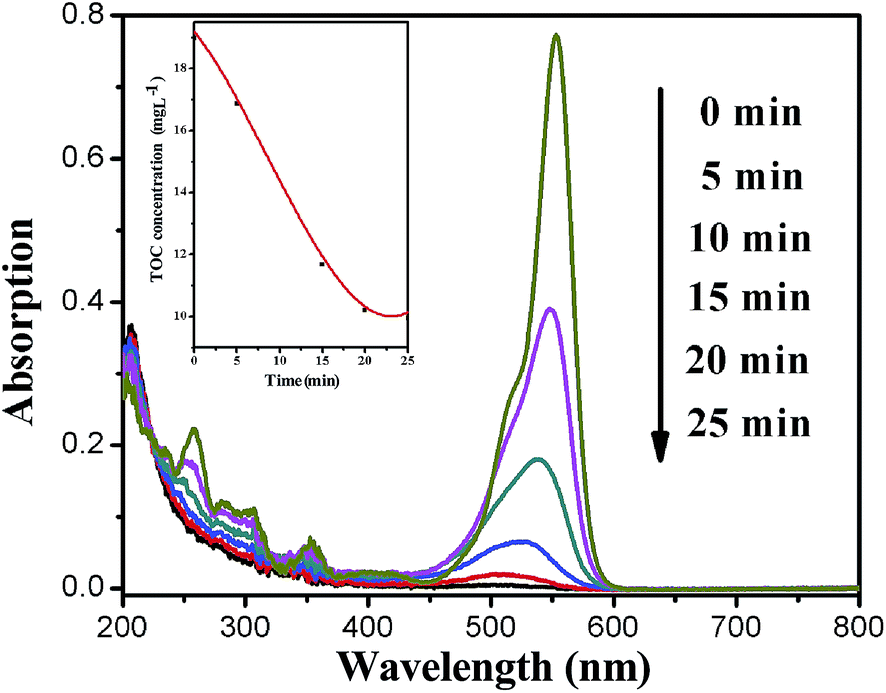 | ||
| Fig. 7 The absorption spectra of a solution of RhB (1.0 × 10⁻⁵ M, 50 mL) in the presence of 2.0 mol% Mn-doped CdS (50 mg) under visible light (λ > 420 nm) irradiation. The inset is the total organic carbon (TOC) removal in thecorresponding solutions at different exposure times. | ||
For further testing of the high activity of the 2 mol% Mn-doped CdS hollow spheres, MO, a typical chemically stable dye that is difficult to decompose, was also chosen as the goal contaminant for photocatalytic degradation under visible light irradiation (λ > 420 nm). Fig. 8 shows the change of the absorption spectra of a MO aqueous solution in the presence of 50 mg of the catalyst. It can be seen that the decomposition of the organic pollutant MO is efficient and the degradation ratio is 99.2% after 50 min, which indicates that the 2.0 mol% Mn-doped CdS hollow spheres show a relatively high photocatalytic performance. To further demonstrate the brilliant photocatalytic activity of 2 mol% Mn-doped CdS hollow spheres, salicylic acid, a typical colorless pollutant which has no light adsorption in the visible light region, was also chosen as the goal contaminant. Fig. 9 shows the UV-vis spectra of salicylic acid versus reaction time. After 4 h irradiation by visible light, salicylic acid is almost completely degraded, which again demonstrates the high activity of our Mn-doped CdS.
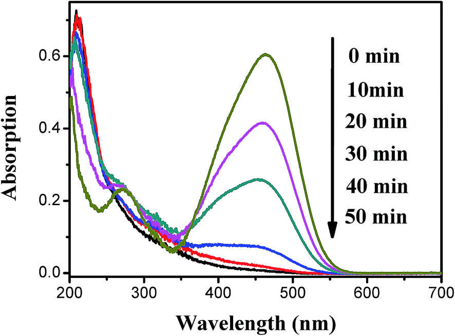 | ||
| Fig. 8 The absorption spectra of a solution of MO (10 mg mL−1, 50 mL) in the presence of 2.0 mol% Mn-doped CdS (50 mg) hollow spheres under visible light (λ > 420 nm) irradiation. | ||
 | ||
| Fig. 9 The absorption spectra of a solution of salicylic acid (20 mg L−1, 50 mL) in the presence of 2.0 mol% Mn-doped CdS (50 mg) under visible light (>420 nm) irradiation. | ||
In order to test the stability of the Mn-doped CdS hollow spheres, we reused the catalyst for four cycles of RhB degradation under visible light (λ > 420 nm) irradiation. As shown in Fig. 10, the catalyst could be reused four times without significant deactivation; after 4 cycles, the stability of the Mn-doped CdS hollow spheres is similar to that of the Ni-doped CdS hollow spheres.30 The corresponding XRD patterns (Fig. 11) have no notable peak shifts before and after the photocatalytic cycles except for a slightly enhanced intensity in the diffraction peaks, indicating the high stability of the Mn-doped CdS hollow spheres.
 | ||
| Fig. 10 Recycled photodegradation of RhB under visible light (>420 nm) irradiation over 2.0 mol% Mn-doped CdS hollow spheres. | ||
 | ||
| Fig. 11 XRD patterns of 2.0 mol% Mn-doped CdS before and after being used four times. | ||
It is well known that the hydroxyl radical (˙OH) is one of the major active species responsible for the photodegradation of organic molecules in the photocatalytic process.44 In order to further investigate the photocatalytic mechanism and the active species involved in the photocatalytic process, the PL technique was employed to detect hydroxyl radicals (˙OH) on the surface of visible light illuminated Mn-doped CdS spheres by using coumarin as a probe molecule.35 Fig. 12 shows the change in the PL spectra of a 5.0 × 10⁻⁴ M coumarin solution with irradiation time in the presence of the 2.0 mol% Mn-doped hollow spheres. A gradual increase in the PL intensity at about 445 nm is observed with increasing irradiation time, indicating the production of ˙OH radicals. However, no increase in PL intensity is observed in the absence of light irradiation or Mn-doped CdS hollow spheres, which confirms that the fluorescence is caused by chemical reactions of coumarin with ˙OH occurring at the Mn-doped CdS hollow spheres–water interface via a photocatalytic reaction.45 From these results, we believe that the rapidly produced and highly accumulated ˙OH radicals may be the main active oxygen species in the photocatalytic process with the Mn-doped CdS hollow sphere system.
 | ||
| Fig. 12 PL spectral changes observed during the visible light illumination (>420 nm) of 2.0 mol% Mn-doped CdS hollow spheres in a 5 × 10⁻⁴ M coumarin solution (excitation at 332 nm). | ||
4. Conclusions
In summary, by varying the molar ratio of different precursors, we have successfully synthesized a series of Mn-doped CdS hollow spheres with the assistance of GSH, which acts as the S source and a gas bubble-template, via a simple hydrothermal method. All the catalysts showed higher photocatalytic activity for the degradation of RhB than commercial Degussa P25 under visible light irradiation. Among the samples, the 2.0 mol% Mn-doped CdS hollow spheres show the highest photocatalytic activity, and the PL spectra demonstrate that ˙OH radicals may be the main active oxygen species in the photocatalytic process. The high photocatalytic activity can have a close relationship with the hollow structure as well as the Mn2+ doping. The hollow structure may favor the harvesting of excited light and facilitate the transportation of reactants and products within the interior space. The doped Mn2+ plays a key role in reducing the recombination rate of photon-generated carriers, thus promoting the activity and stability of the catalyst. The method and ideas described herein will provide a new way to synthesize not only Mn-doped CdS hollow spheres, but also other semiconductor materials.Conflict of interest
The authors declare no competing financial interest.Acknowledgements
This work was supported by the Natural Science Foundation of Hubei Province (2013CFA089).References
- Y. K. Lai, J. Y. Huang, H. F. Zhang, V. P. Subramaniam, Y. X. Tang, D. G. Gong, L. Sundar, L. Sun, Z. Chen and C. J. Lin, J. Hazard. Mater., 2010, 184, 855–863 CrossRef CAS PubMed.
- X. H. Tang and D. Y. Li, J. Phys. Chem. C, 2008, 112, 5405–5409 CAS.
- P. Roy, S. Berger and P. Schmuki, Angew. Chem., Int. Ed., 2011, 50, 2904–2939 CrossRef CAS PubMed.
- S. W. Liu, J. G. Yu and M. Jaroniec, J. Am. Chem. Soc., 2010, 132, 11914–11916 CrossRef CAS PubMed.
- X. H. Li, J. S. Zhang, X. F. Chen, A. Fischer, A. Thomas, M. Antonietti and X. C. Wang, Chem. Mater., 2011, 23, 4344–4348 CrossRef CAS.
- M. Ibáñez, J. D. Fan, W. H. Li, D. Cadavid, R. Nafria, A. Carrete and A. Cabot, Chem. Mater., 2011, 23, 3095–3104 CrossRef.
- Z. Y. Liu, H. W. Bai and D. Sun, Appl. Catal., B, 2011, 104, 234–238 CrossRef CAS PubMed.
- M. Luo, Y. Liu, J. C. Hu, J. L. Li, J. Liu and R. M. Richards, Appl. Catal., B, 2012, 125, 180–188 CrossRef CAS PubMed.
- Y. Ishibai, J. Sato, T. Nishikawa and S. Miyagishi, Appl. Catal., B, 2008, 79, 117–121 CrossRef CAS PubMed.
- Y. Liu, L. F. Chen, J. C. Hu, J. L. Li and R. Richards, J. Phys. Chem. C, 2010, 114, 1641–1645 CAS.
- Y. Liu, J. C. Hu and J. L. Li, J. Alloys Compd., 2011, 509, 5152–5158 CrossRef CAS PubMed.
- X. Chen, L. Liu, P. Y. Yu and S. S. Mao, Science, 2011, 331, 746–750 CrossRef CAS PubMed.
- Y. J. Xu, Y. B. Zhuang and X. Z. Fu, J. Phys. Chem. C, 2010, 114, 2669–2676 CAS.
- M. F. Wu, Y. N. Jin, G. H. Zhao, M. F. Li and D. M. Li, Environ. Sci. Technol., 2010, 44, 1780–1785 CrossRef CAS PubMed.
- K. L. Lv, Q. J. Xiang and J. G. Yu, Appl. Catal., B, 2010, 104, 275–281 CrossRef PubMed.
- D. J. Wang, D. S. Li, G. Li, F. Fu, Z. P. Zhan and Q. T. Wei, J. Phys. Chem. C, 2009, 113, 5984–5990 CAS.
- G. Z. Shen and C. J. Lee, Cryst. Growth Des., 2005, 5, 1085–1089 CAS.
- J. Zhang, S. W. Liu, J. G. Yu and M. Jaroniec, J. Mater. Chem., 2011, 21, 14655–14662 RSC.
- A. P. Davis and C. P. Huang, Water Res., 1991, 25, 1273–1278 CrossRef CAS.
- F. Chen, R. J. Zhou, L. G. Yang, N. Liu, M. Wang and H. Z. Chen, J. Phys. Chem. C, 2008, 112, 1001–1007 CAS.
- X. Zong, G. P. Wu, H. J. Yan, G. J. Ma, J. Y. Shi, F. Y. Wen, L. Wang and C. Li, J. Phys. Chem. C, 2010, 114, 1963–1968 CAS.
- G. S. Li, D. Q. Zhang and J. C. Yu, Environ. Sci. Technol., 2009, 43, 7079–7085 CrossRef CAS.
- T. Gao and T. H. Wang, Chem. Commun., 2004, 2558–2559 RSC.
- J. Choi, S. Y. Ryu, W. Balcerski, T. K. Lee and M. R. Hoffmann, J. Mater. Chem., 2008, 18, 2371–2378 RSC.
- X. J. Lv, F. Q. Huang, X. L. Mou, Y. M. Wang and F. F. Xu, Adv. Mater., 2010, 22, 3719–3722 CrossRef PubMed.
- S. L. Xiong, X. G. Zhang and Y. T. Qian, Cryst. Growth Des., 2009, 9, 5259–5265 CAS.
- T. Shanmugapriya, R. Vinayakan, K. G. Thomas and P. Ramamurthy, CrystEngComm, 2011, 13, 2340–2345 RSC.
- Y. Shemesh, J. E. Macdonald, G. Menagen and U. Banin, Angew. Chem., Int. Ed., 2011, 50, 1185–1189 CrossRef CAS PubMed.
- J. X. Li, J. H. Xu, W. L. Dai, H. X. Li and K. N. Fan, Appl. Catal., B, 2009, 85, 162–170 CrossRef CAS PubMed.
- M. Luo, Y. Liu, J. C. Hu, H. Liu and J. L. Li, ACS Appl. Mater. Interfaces, 2012, 4, 1813–1821 CAS.
- O. Goede and W. Heimbrodt, Phys. Status Solidi A, 1988, 146, 11–62 CrossRef CAS.
- L. B. Yu, Z. Li, Y. B. Liu, F. Cheng and S. Q. Sun, Mn-doped CdS quantum dots sensitized hierarchical TiO2 flower-rod for solar cell application, Appl. Surf. Sci., 2014, 305, 359–365 CrossRef CAS PubMed.
- M. Yan, G. Z. Dai, S. Hu, Q. L. Zhang and B. S. Zou, Mater. Lett., 2011, 65, 2522–2525 CrossRef CAS PubMed.
- C. W. Cheng, G. Y. Xu, H. Q. Zhang, H. Wang, J. M. Cao and H. M. Ji, Mater. Chem. Phys., 2006, 97, 448–451 CrossRef CAS PubMed.
- Y. Liu, J. C. Hu, T. F. Zhou, R. C. Che and J. l. Li, J. Mater. Chem., 2011, 21, 16621–16627 RSC.
- D. Anshu, P. Vijay and S. K. Rathore, Catal. Commun., 2012, 28, 90–94 CrossRef PubMed.
- Y. N. Huo, M. Miao, Y. Zhang, J. Zhu and H. X. Li, Chem. Commun., 2011, 47, 2089–2091 RSC.
- X. W. Lou, L. A. Archer and Z. C. Yang, Adv. Mater., 2008, 20, 3987–4019 CrossRef CAS.
- X. H. Zhang, D. W. Jing and L. J. Guo, Int. J. Hydrogen Energy, 2010, 35, 7051–7057 CrossRef CAS PubMed.
- W. Zhao, C. Chen, X. Li and J. Zhao, Photodegradation of sulforhodamine-B dye in platinum as a functional co-catalyst, J. Phys. Chem. B, 2002, 106, 5022–5028 CrossRef CAS.
- N. U. Silvaa, T. G. Nunesb, M. S. Saraiva, M. S. Shalamzari, P. D. Vaz, O. C. Monteiroa and C. D. Nunes, Appl. Catal., B, 2012, 113–114, 180–191 CrossRef PubMed.
- D. Chen and J. H. Ye, Adv. Funct. Mater., 2008, 18, 1922–1928 CrossRef CAS.
- H. B. Fu, C. S. Pan, W. Q. Yao and Y. F. Zhu, J. Phys. Chem. B, 2005, 109, 22432–22439 CrossRef CAS PubMed.
- T. Hirakawa, K. Yawata and Y. Nosaka, Appl. Catal., A, 2007, 325, 105–111 CrossRef CAS PubMed.
- C. S. Turch and D. F. Ollis, J. Catal., 1990, 122, 178–192 CrossRef.
| This journal is © The Royal Society of Chemistry 2015 |