
Mechanism of oil molecules transportation in nano-sized shale channel: MD simulation†
Qingzhong Xue*ab,
Yehan Taoab,
Zilong Liua,
Shuangfang Lu*c,
Xiaofang Lia,
Tiantian Wua,
Yakang Jina and
Xuefeng Liub
aState Key Laboratory of Heavy Oil Processing, China University of Petroleum, Qingdao 266580, Shandong, P. R. China. E-mail: xueqingzhong@tsinghua.org.cn; Fax: +86-0532-86981169; Tel: +86-0532-86981169
bCollege of Science, China University of Petroleum, Qingdao 266580, Shandong, P. R. China
cInstitute of Unconventional Oil & Gas and New Energy, China University of Petroleum, Qingdao 266555, Shandong, P. R. China. E-mail: lushuangfang@qq.com
First published on 23rd February 2015
Abstract
Unconventional energy, such as shale oil and gas, opens up a new avenue for alleviating the pressure on the use of conventional energy, enabling a sustainable development of economy and industry. We firstly explored the mechanism of oil molecules transportation in a nano-sized shale channel by molecular dynamic simulations. It is demonstrated that the competition between the oil adsorption strength to the shale surface and the driving force from gas flooding (N2) plays the dominant role in the oil translocation process in the shale channel. The encapsulated oil molecules would be expelled by gas flooding when the gas pressure reaches a critical value. Besides, it is found that the pressure of the gas flooding, shale channel pore size, N2 amount, temperature and shale component all have an important effect on the translocation process of oil molecules inside the shale channel, whose oil-driving efficiency is characterized by oil displacement distance and oil displacement loss. This work lays a theoretical foundation to achieve effectively and efficiently exploiting oil. Besides, the result may shed light on explaining many industrial processes and natural phenomena in nano-sized channels, including viscous liquid transport or diffusion through membranes, energy conversion devices, biological molecules (hemoglobin, protein, DNA) translocation and so forth.
Introduction
The rapid development of economy and society results in an increasing demand for energy, but unfortunately, due to the excessive consumption of conventional energy, the contradiction between the supply and demand of energy becomes more prominent, posing a challenge to sustainable development of human society. Unconventional oil has triggered off enormous scientific interest due to its huge reserves,1,2 which endows it with great potential to release the stress of conventional energy crisis.3–5 Shale oil is short for mature-organic shale oil, the most representative energy listed under the unconventional energy headings, which refers to the petroleum preserved in nano-scale pores in organic-rich shale.6 In order to pave the way for further shale oil exploration, including optimizing production and determining economic feasibility, knowledge of the physical aspects of shale oil storage and the transport mechanism is urgently required. A lot of efforts have been made to explore the interface interaction between oil or gas/substrate,7–9 oil/oil-displacing agent,10 oil-displacing agent/substrate,11–13 or ternary phase interaction.14–16 Besides, the formation mechanism of shale oil is widely investigated.6,17,18 Although much progress has been achieved in both theoretical and experimental studies on shale oil storage, the most important question of how oil molecules transport in shale channels remains unanswered.Shale oil, generally light oil with low viscosity, occurs in adsorption state in nanoscale shale channels, which is a common consequence of the attractive interaction between adjacent oil molecules and the attractive interaction between oil molecules and channel walls. This results in oil molecules being really difficult to transport in shale channels without the assistance of an external driving force. Water flooding and gas flooding are common external driving force in bulk systems. However, since oil recovery from water flooding relies on spontaneous imbibition of water to expel oil from the matrix into the fracture system. In oil- or mixed-wet shale reservoirs, the capillary driving force for the spontaneous imbibition process is weak, and therefore the water flooding oil recovery efficiency is low.15 Gas flooding is not restricted by the wettability of shale surface because the interaction between gas molecules and shale reservoirs is much weaker. Therefore, gas flooding may be an effective method to exploit shale oil.
The diameter of pores in shale oil sediments ranges from only a few nanometers to a few micrometers, which means the transport process of shale oil in a shale system is different from that in a bulk system due to the high surface-to-volume ratio in shale channels. This makes the evaluation of the gas driving oil transport process inside shale channels using conventional laboratory techniques a challenging problem. In addition, because of the size restriction, Cauchy and Navier–Stokes equations, which can be used to derive the Poiseuille and other continuum-level flow relations, cannot be applied in nano-sized fluid, thus hindering our further understanding of the mechanism of oil transportation in nano-sized channels. Recently, it has been demonstrated that molecular dynamics (MD) simulation is a powerful method to understand the transport mechanism in nano-sized systems.19–23 For instance, MD simulation has been widely used to study nanofluid, such as water flow inside carbon nanotubes,20,21,24–27 argon transport inside a nanopore19 and surfactant filling carbon nanotubes.22 Furthermore, Yu et al. employed MD simulation to study the transport of water molecules along carbon nanotubes under the driving force of methane molecules.28 Our group has investigated the release of encapsulated molecules from carbon nanotubes using a displacing method by MD simulation.29
In this paper, the mechanism of oil molecules transported in nano-sized shale channel was intensively studied using MD simulations. It is found that the pressure of gas flooding, shale channel pore size, N2 amount, temperature and shale component should all be taken into consideration in the translocation process of oil molecules inside nano-sized channel. The MD simulation provides further information for fundamental understanding of the oil translocation process in nanoscale channels, which is conducive in guiding the oil-displacing gas design, oil recovery enhancement, ore flotation, detergency and printing. Moreover, our investigations hold sway on many biological applications including DNA and RNA transport through cell membrane, gene swapping between the guest and host bacteria through pili, as well as many other fields such as membrane separation of mixtures, gas storage device, electro kinetic micron size channel battery and so on.19,30–34
Modeling and methods
MD simulation method was employed to simulate the infinite system. The interatomic interactions were described by the force field of a condensed-phase optimized molecular potential for atomistic simulation studies (COMPASS).35 COMPASS is a parameterized, tested and validated first ab initio force field, which enabled accurate and simultaneous prediction of various gas-phase properties and condensed-phase properties of most of common organic and inorganic materials.36–38 The Anderson thermostat method was employed to control the temperature of the system, the VDW interactions were calculated within a cutoff distance of 9.5 Å, and the Ewald method was applied for the calculation of electrostatic interactions.38–42 Interactions between oil molecules, gas molecules, oil molecules and gas molecules, oil or gas molecule and shale channels, were treated using a Lennard-Jones potential, which has been widely used to describe the above interactions in shale system.7–10,12,14 Periodic boundary conditions were applied in all three dimensions.In our work, silica (Fig. 1(a)) and dodecane (C12H26) (Fig. 1(b)) are selected as typical components of the shale substrate and oil droplet, respectively. The shale channel model was constructed by building a silica supercell with dimensions of 44.217 Å × 43.242 Å × 148.917 Å and digging a 3 nm square hole in the middle of the supercell along the direction of z axis (as seen in Fig. 1(c)). A vacuum of 38 Å was applied along the direction of z axis to eliminate the effect of periodic boundary condition. Then 74 dodecane molecules were inserted into the hollow cavities of the silica supercell near the left end of the channel. To find the thermally stable morphology of oil molecules inside a shale channel and achieve a configuration with minimum potential energy, energy minimization was performed. Due to the mixed-wet silica surface, arousing an attractive force for oil molecules, the oil droplet was intensively adsorbed inside the channel and almost kept its initial shape.14 This minimum energy conformation was used as the initial status in the following MD simulations. The gas flooding, namely, N2 molecules flooding, was initially placed near the opening at left end of the shale channel along the direction of z axis. Six types of N2 boxes with same box parameter but different gas initial pressures were set up to study the “start-up pressure” for N2 driving oil transport in shale channel. A thin silica wall was put at the left side of N2 box to prevent the diffusion of N2 molecules directly into the vacuum phase. The silica channel and wall were kept fixed. The total length of the model was 217.65 Å (see in Fig. 1(d)).
 | ||
| Fig. 1 (a) Silica surface, (b) dodecane molecule, (c) 3 nm silica channel with 74 oil molecules inside, (d) N2 driving dodecane transport model. | ||
We then put the model into a NVT ensemble, a fixed time step of 1 fs was used and data were collected every 5 ps. A 2.5 ns simulation time was performed for all calculations. The full-precision trajectory was then recorded, and the results were analyzed. Our MD simulations were carried out using Discover code embedded in the Material Studio software.
Results and discussion
Start-up pressure
The pressure of gas flooding has great influence on the transport process of oil molecules inside a nano-sized silica shale channel, so we first determined the candidate start-up pressure for N2 flooding. Shale oil generally occurs in adsorption state in nanoscale shale channels, which is a common consequence of the attractive interaction between adjacent oil molecules and the attractive interaction between oil molecules and channel walls. The applied external force needs to overcome this attractive interaction to realize the translocation process of oil droplet. As we can see in Fig. 4(a) and (b), the translocation distance less than 15 Å (the radius of oil droplet) is not obvious, which has no meaning for the industrial exploiting of shale oil. So we considered that only when the external pressure makes the oil droplet have a translocation distance more than 15 Å, this external pressure can be called the “start-up” pressure. Six types of N2 pressures were simulated, with initial pressure intensity of 5 MPa, 10 MPa, 20 MPa, 30 MPa, 40 MPa and 50 MPa, respectively, and for comparison, a shale oil model without N2 flooding (0 MPa) was also constructed (see in Fig. 2). Then, we performed a 2.5 ns dynamic process to observe the oil translocation process. Furthermore, the oil concentration profiles along the z axis were calculated, the left end of the model was set as zero point, as shown in Fig. 3. For clarity, we just show the oil concentration profiles of 0 MPa, 5 MPa, 30 MPa and 50 MPa, while other oil concentration profiles for 10 MPa, 20 MPa and 40 MPa can be found in Fig. s1 of ESI.† The peak in the curve of the oil concentration profile is defined as the center of oil droplet and the difference between the oil centers in the silica shale channel under 0 MPa and that under other N2 pressure is regarded as the oil displacement distance under N2 driving. Combining Fig. 2 and 3, during a 2.5 ns simulation, no obvious oil translocation is observed under 0 MPa model, except for a small amount of oil molecules spreading on the silica surface because of the van der Waals interactions between oil molecules and silica surface. This illustrates that dodecane molecules prefer to stay near the surface of silica and cannot transport in silica shale channels spontaneously without the help of a driving force.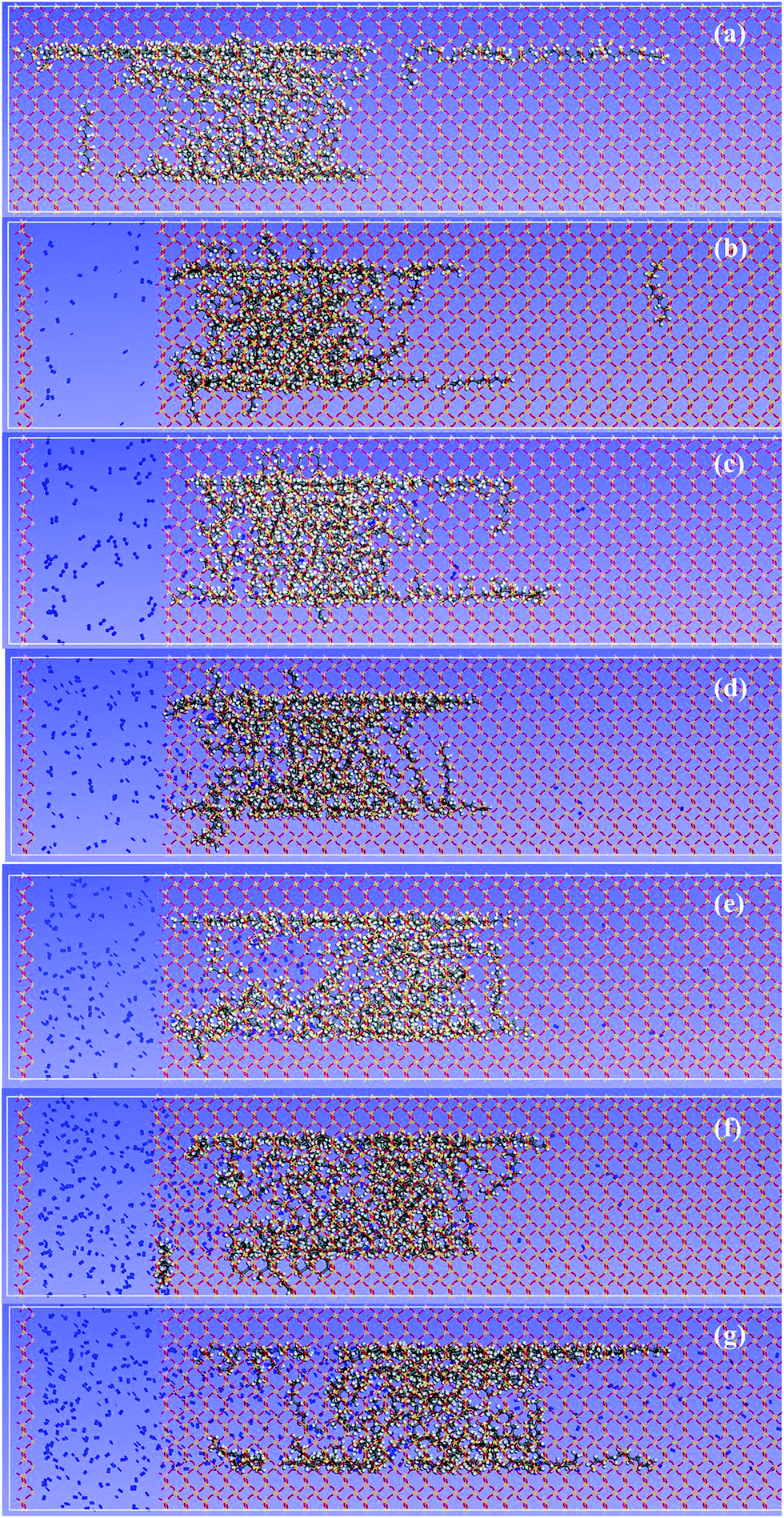 | ||
| Fig. 2 Final configurations of dodecane molecules inside silica shale channel after N2 driving – with N2 initial pressure of (a) 0 MPa, (b) 5 MPa, (c) 10 MPa, (d) 20 MPa, (e) 30 MPa, (f) 40 MPa and (g) 50 MPa. Red, yellow, grey, white and blue balls represent O, Si, C, H and N atoms, respectively. | ||
 | ||
| Fig. 3 Dodecane concentration profiles (Gaussian fitting) in final configuration of N2 driving oil transport inside silica shale channel with N2 initial pressure of 0 MPa, 5 MPa, 30 MPa and 50 MPa. | ||
Compared to not using N2 flooding, oil droplets with a driving force of 5–20 MPa reveal a very small displacement distance (less than 12 Å), which means the driving force coming from these low-pressure N2 flooding is not sufficient to give rise to the transport of oil molecules. An apparent translocation is shown in the 30 MPa model, where the oil center shows a displacement of about 26.827 Å. When the N2 pressure further increased to 40 MPa, the displacement is similar to that at 30 MPa. But there is another obvious growth of oil displacement in the 50 MPa model, with an oil displacement distance of approximately 33.48 Å. The displacement distance witnesses an increase with the ascending N2 pressure, but noticing that 30 MPa has the optimal balance between the oil recovery and economic feasibility among the pressures we tested because higher N2 pressure means higher operation difficulties and the risk of gas storage and transport increased, so we performed all the following discussions based on the 30 MPa model. Of course the start-up pressure is decided by many factors as we discuss below, such as the oil and shale component, the pore size of the channel, temperature and so forth. Therefore, we are only able to give the relation between two factors. For example, the relation between the pore size and the applied nitrogen pressure can be calculated by fixing the pore size and changing the applied nitrogen pressure. So 30 MPa is only the start-up pressure for a 3 nm dodecane shale oil droplet inside 3–5 nm silica channels at 298 K.
Transport process
The transport process of oil molecules inside a nano-sized silica shale channel under 30 MPa is shown in Fig. 4. And the whole dynamic process can be seen in Video S1 of ESI.† The initial optimized configuration is shown in Fig. 4(a). Because of the presence of N2 flooding, the oil molecules begin to transport in silica shale channel. The whole process can be divided into three stages. In the first stage, before 500 ps, N2 flooding can be seen as compressed N2 which can generate a driving force and induce the transport of oil droplet inside the silica shale channel. Theoretically, dodecane molecules become unstable thermodynamically and the aggregates of oil molecules are disturbed. Simultaneously, the structural change of oil droplets is observed, as seen Fig. 4(b) at 250 ps. | ||
| Fig. 4 Snapshops of the dodecane molecules transport process in silica shale channel at (a) 0 ps, (b) 250 ps, (c) 1000 ps, (d) 2000 ps, (e) 2500 ps and (f) 3500 ps. | ||
The second stage corresponds to the oil droplet translocation process before 1000 ps. With the N2 molecules filling the channel and occupying the cavity space, the oil molecules are gradually expelled from the channel. The oil molecules near the N2 flooding move forward and the adjacent oil molecules continuously moved to the right side of the channel, due to the interaction among oil molecules. The former oil molecules on the right side of the oil droplet near the silica surface become adsorbed during the movement because of the attractive interaction of the silica surface and its cavity would be replaced by the back oil molecules.
Finally, the translocation of oil molecules inside the channel occurred after 1000 ps simulation and the oil molecules start to move to the right side of the channel under the driving force of N2 molecules. It should be noticed that the oil molecules adsorbed on silica surface remain difficult to be expelled by N2 flooding, the main reason is that the strong adsorption energy of silica surface acts as an energy barrier preventing oil molecules near silica surface from running away, thus forming an adsorption layer on the surface of silica, the thickness of which is about one oil molecule size. With an increase of the adsorbed layer, the diameter of the oil droplet becomes smaller during the translocation process and undeniably causes the loss of oil during the exploiting process. Another point that should be noted is that in the whole process, N2 molecules demonstrate poor dissolution ability into the oil molecules because few N2 molecules are observed to diffuse into the oil droplet, which is beneficial to the driving of oil molecules. The pressure of N2 decreases to some extent because of the diffusion of N2 molecules in the channel.
Pore size effect
In nanoscale, the effects of volume forces, which dominate the fluid properties on a large scale, are weakened, and the impacts of surface forces are enhanced. A key topic in the studies of flow in nanochannel is how the interaction between the fluid molecules and the surface will affect the liquid flow. In general, this interaction depends greatly on the surface-to-volume ratio of the channel, which is very big in shale channels. This is because the pore diameter of the shale channel is only a few nanometers and the smaller the pore size is, the bigger the surface-to-volume ratio is. To further study the effect of surface-to-volume ratio on the transport of oil molecules, we study the transport of oil molecules through other two kinds of silica shale channels with different pore sizes. The pores of the silica shale channels considered are 4 nm and 5 nm square pores in the middle of the silica supercell. Six types of N2 pressures were simulated, with same initial pressure intensities as that of 3 nm model. The oil displacement inside different pore size silica shale channels under different N2 initial pressure are shown in Fig. 5(a).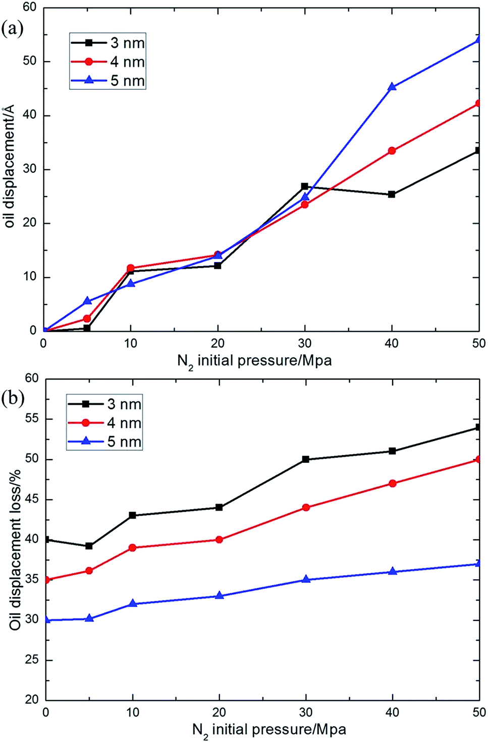 | ||
| Fig. 5 (a) Oil displacements inside different pore size silica shale channels under N2 pressure from 0–50 MPa. (b) Oil displacement loss inside different pore size silica shale channels under N2 pressure from 0–50 MPa. | ||
During a 2.5 ns simulation, little oil translocation is observed for the 0 MPa model, in spite of the spread of a small amount of oil molecules on silica surface because of the attractive interaction between the oil molecules and silica surface. For all three kinds of channels, before adding N2 flooding of 30 MPa, the oil displacements are not obvious (less than 15 Å) and demonstrate a slow climbing tendency with the growing of the N2 driving pressure and the displacement distance is quite similar for three kinds of pore size. Whereas, a rather different case is observed when a 30 MPa N2 initial pressure is applied. The oil displacement distance witnesses a significant rise to about 30 Å, almost double that under 20 MPa. The oil displacements of a 3 nm pore at 30 MPa and 40 MPa are similar and this difference can be ignored in our system. In fact, the oil displacement of a 3 nm pore is smaller than that of 4 nm and 5 nm pores under 40 MPa and 50 MPa because of the stronger average attractive interaction between oil molecules and silica channel, which means it is really hard to stimulate the translocation process in small shale channels. The differences of oil displacements are obvious at higher applied pressures. When we further increase the N2 initial pressure, the oil displacement distance in different pores varies differently from each other. The oil displacement in a 3 nm channel with the smallest pore size displays the smallest oil displacement distance and does not see any further increase under higher N2 initial pressure. However, the oil displacement in 4 nm and 5 nm channels displays an apparent increase under higher N2 initial pressure and the biggest (5 nm) channel shows the biggest oil displacement distance.
In addition to the oil displacement distance, we found that the oil displacement loss varies greatly with pore size. The oil displacement loss is defined as the ratio between the number of oil molecules “adsorbed” on the silica surface and the number of total oil molecules in our simulation. It should be pointed out that if over half of the atoms in a single molecule are adsorbed on the silica surface, we consider that this molecule is “adsorbed”. The oil displacement loss of three different pore size models under different N2 initial pressure are shown in Fig. 5(b). The oil displacement loss witnesses an increasing trend with a decreasing pore size, which means that oil molecules in a smaller pore channel prefer to stay on surface of the silica surface rather than moving under the driving force of the N2 flooding. It is the competition between the average adsorption strength of oil molecules to silica surface and the driving force from the gas flooding plays a significant role on the oil displacement loss. In smaller pore channels, the average adsorption strength of oil molecules to silica surface occupies the dominant status and oil molecules are strongly adsorbed on the silica surface, causing oil displacement loss in the driving process. Whereas, the driving force coming from the N2 flooding reveals its advantage in larger pore channels, in which the average adsorption strength of oil molecules to silica surface is greatly weakened, thus a smaller oil displacement loss is expected.
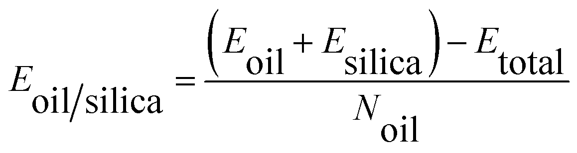
From the above discussions, it is identified that the average adsorption strength of oil molecules to the shale surface has a great influence on the oil transport process. We calculated the interaction energy between oil molecules and shale channels to evaluate the average adsorption strength of oil molecules, and it could be calculated as follows:
 | (1) |
 | ||
| Fig. 6 Average adsorption strength of oil molecules to different shale channels under N2 pressure from 0–50 MPa. | ||
N2 number effect
The effect of N2 amount, temperature and shale component on the N2 driving efficiency of the oil transportation inside 3 nm silica shale channel is investigated with N2 initial pressure of 30 MPa. The N2 flooding with same N2 pressure but with a different N2 amount (the number of N2 molecules is 150, 300, 450, 600 and 750) as the driving force can trigger off the translocation of oil molecules inside a 3 nm silica shale channel, as shown in Fig. 7, which demonstrates the snapshots of the final configuration of these models after a 2.5 ns simulation. It is found that 150 N2 molecules make the oil molecules center to move 5.236 Å in Fig. 7(a), while 300 N2 molecules render them to move 26.827 Å in Fig. 7(b) and 750 N2 molecules drive them to transport 30.175 Å shown in Fig. 7(e). Therefore, we suggest that the continuous driving force generated by 750 N2 molecules is larger than that by 150 and 300 N2 molecules and the increase of N2 molecules is beneficial to the reduction of the extracting time of oil molecules from silica shale channels. As shown in Fig. 7, the displacement distance of oil molecules displays a roughly linear trend relative to the number of N2 molecules, resulting in an increasing translocation rate of oil molecules. When the N2 molecule number is 750, the velocity of oil movement can reach up to 12.07 Å ns−1, almost six times faster than that in the case of 150 N2 molecules, 2.094 Å ns−1. Another point that should be noted is that the displacement distance of oil molecules are quite similar when the number of N2 molecules is larger than 300. | ||
| Fig. 7 Final configurations of N2 driving transport in 3 nm silica shale channel with N2 number of (a) 150, (b) 300, (c) 450, (d) 600 and (e) 750. | ||
Temperature effect
Some previous investigations indicated that shale oil is relatively easy to recover from nano-scale pore-throats in subsurface shale under high temperature theoretically.6,43 Previously, we have studied the effect of temperature on the adhesion energy between the polymers and SWNTs.44,45 Using the same method, we have carried out additional MD simulations at different temperatures on a system of a 3 nm silica shale channel with N2 initial pressure of 30 MPa to study the temperature effect. The temperatures vary from 348 K to 498 K in steps of 50 K. The oil displacement distance is compared with the results obtained at 298 K in Fig. 8 as a function of simulation time. | ||
| Fig. 8 Oil displacement inside a 3 nm silica shale channel after N2 driving with 30 MPa N2 initial pressure as a function of simulation time under different temperatures. | ||
As shown in Fig. 8, a higher temperature is beneficial to stimulate the oil molecules translocation in the same channel under the same N2 pressure. The oil droplet was initially observed a displacement distance of 2 Å at ∼250 ps during the driving simulation for the temperature of 298 K, while this displacement distance was generated at 25 ps with the temperature of 498 K, almost 10 times faster than that of 298 K. From 250 ps to 2500 ps, the higher the temperature is, the more the oil center displacement distance is when reaching the same simulation time. After 2.5 ns simulation, the oil center displacement is 26.827 Å, 28.437 Å, 31.827 Å, 42.317 Å and 52.827 Å for the temperature of 298 K, 348 K, 398 K, 448 K and 498 K, respectively. Higher temperatures cause higher oil displacement distances which is conducive to enhance the yields and velocity of oil recovery. It is possibly attributed to the higher kinetic energy of the fluid, which cause the instability of oil molecules thermodynamically,46 as we can observe from the molecular dynamic trajectories. This explanation is in agreement with transport of water molecules in carbon nanotubes at higher temperatures.27
Shale component effect
As seen from the previous calculations, the sorption characteristics of oil to silica shale channel is greatly determined by the adsorption interaction energy between oil molecules and shale substrates, which makes a difference on the final oil driving efficiency and yield. In general, the shale components have either high Si ratios, such as silica, or enriched with carbonate, such as calcite and dolomite. Therefore, we further simulated the N2 driving oil transport process in calcite and dolomite shale channels to investigate the effect of shale component on the transportation properties of oil molecules inside shale channels and the final configurations of oil molecules inside the three different shale channels after a 2.5 ns simulation are shown in Fig. 9. | ||
| Fig. 9 Final configurations of oil molecules inside (a) silica, (b) calcite and (c) dolomite channels after N2 driving. | ||
It was found that distinct oil transport happened for silica and calcite channels, indicating that the N2 flooding is capable of impelling oil molecules and moving in these two channels. For a silica channel, the oil center displacement distance is appropriate 26.827 Å, while it is much shorter in a calcite channel and reaches about 11.3 Å at the end of the simulation. On the countrary, for oil droplet in a dolomite channel, the oil center almost keeps its position during the whole simulation, except for some spreading of oil molecules to the dolomite surface.
The different oil transportation properties should be ascribed to the different interaction between oil molecules and shale channels. Here, the interactions are calculated using eqn (1). The dolomite component showed the strongest interaction energy of 359.1 kcal mol−1 and it is followed by calcite component of 275.12 kcal mol−1. However, the silica substrate holds the slightest interaction energy of only 43.98 kcal mol−1. It is obvious that the higher the interaction energy is, the harder the translocation process is, the stronger the oil adsorption strength to shale surface is, and so the critical pressure of gas flooding to transport oil molecules inside shale channel is larger. In other words, the start-up pressure of oil transportation inside the dolomite shale channel is the largest, when the sizes of the shale channels are the same.
Conclusion
In summary, the mechanism of oil molecules transportation in nano-sized shale channel was explored for the first time using MD simulation. It is demonstrated that N2 flooding can successfully drive dodecane molecules to transport in silica and calcite shale channels when the gas pressure reaches a critical value, called start-up pressure. Further simulations identified that channel size, N2 amount, temperature and shale component all have influences on the start-up pressure of driving oil molecules translocation and oil translocation efficiency. This can be explained by the competition between the adsorbed strength of the shale surface and the driving force from the N2 flooding. Oil translocation in bigger pore size channels displays an apparent increase in oil displacement distance and decrease in oil displacement loss. Moreover, increasing the N2 molecules number and the increasing of temperature are also favourable to the translocation of the oil droplet and the driving rate is also enhanced. The oil molecules in a dolomite channel are hard to translocate under the present driving pressure. Our findings will provide insights for predicting oil or viscous fluid transport in nano-sized channels and develop reservoir simulators for production optimization.Acknowledgements
This work is supported by the Natural Science Foundation of China (41330313), Taishan Scholar Foundation (ts20130929), the Fundamental Research Funds for the Central Universities (14CX05013A), Graduate student innovation fund (14CX06087A) and National Super Computing Center in Jinan.References
- J. D. Hughes, Nature, 2013, 494(7437), 307–308 CrossRef CAS PubMed.
- S. Wang, X. Jiang, X. Han and J. Tong, Energy, 2012, 42(1), 224–232 CrossRef CAS PubMed.
- F. Javadpour, D. Fisher and M. Unsworth, J. Can. Pet. Technol., 2007, 46(10), 55–61 CAS.
- S. D. Mohaghegh, J. Nat. Gas Sci. Eng., 2013, 12, 22–33 CrossRef PubMed.
- X. Jiang, X. Han and Z. Cui, Energy, 2007, 32(5), 772–777 CrossRef PubMed.
- C. Zou, Z. Yang, J. Cui, R. Zhu, L. Hou, S. Tao, X. Yuan, S. Wu, S. Lin and L. Wang, Adv. Pet. Explor. Dev., 2013, 40(1), 15–27 CrossRef.
- D. J. Ross and R. Marc Bustin, Mar. Pet. Geol., 2009, 26(6), 916–927 CrossRef CAS PubMed.
- J. Zhong, X. Wang, J. Du, L. Wang, Y. Yan and J. Zhang, J. Phys. Chem. C, 2013, 117(24), 12510–12519 CAS.
- H. Hu, X. Li, Z. Fang, N. Wei and Q. Li, Energy, 2010, 35(7), 2939–2944 CrossRef CAS PubMed.
- Q. Liu, S. Yuan, H. Yan and X. Zhao, J. Phys. Chem. B, 2012, 116(9), 2867–2875 CrossRef CAS PubMed.
- H. Du and J. D. Miller, Langmuir, 2007, 23(23), 11587–11596 CrossRef CAS PubMed.
- X. Hu, Y. Li, H. Sun, X. Song, Q. Li, X. Cao and Z. Li, J. Phys. Chem. B, 2010, 114(27), 8910–8916 CrossRef CAS PubMed.
- N. R. Tummala, L. Shi and A. Striolo, J. Colloid Interface Sci., 2011, 362(1), 135–143 CrossRef CAS PubMed.
- J. Zhong, P. Wang, Y. Zhang, Y. Yan, S. Hu and J. Zhang, Energy, 2013, 59, 295–300 CrossRef CAS PubMed.
- M. Salehi, S. J. Johnson and J.-T. Liang, Langmuir, 2008, 24(24), 14099–14107 CrossRef CAS PubMed.
- A. C. van Duin and S. R. Larter, Org. Geochem., 2001, 32(1), 143–150 CrossRef CAS.
- H. J. Vinegar, E. P. de Rouffignac, K. A. Maher, L. G. Schoeling and S. L. Wellington, US Pat., 17:2008/2014593, 2010.
- E. P. de Rouffignac, I. E. Berchenko, T. D. Fowler, J. M. Karanikas, K. A. Maher, R. C. Ryan, G. T. Shahin Jr, H. J. Vinegar, S. L. Wellington and E. Zhang, US Pat., US6951247 B2, 2005.
- C. Huang, K. Nandakumar, P. Y. Choi and L. W. Kostiuk, J. Chem. Phys., 2006, 124(23), 234701 CrossRef PubMed.
- J. A. Thomas, A. J. McGaughey and O. Kuter-Arnebeck, Int. J. Therm. Sci., 2010, 49(2), 281–289 CrossRef CAS PubMed.
- J. A. Thomas and A. J. McGaughey, Phys. Rev. Lett., 2009, 102(18), 184502 CrossRef.
- E. J. Carvalho and M. C. dos Santos, ACS Nano, 2010, 4(2), 765–770 CrossRef CAS PubMed.
- Y. Li, J. Xu and D. Li, Microfluid. Nanofluid., 2010, 9(6), 1011–1031 CrossRef.
- S. Joseph and N. Aluru, Nano lett., 2008, 8(2), 452–458 CrossRef CAS PubMed.
- J. A. Thomas and A. J. McGaughey, Nano lett., 2008, 8(9), 2788–2793 CrossRef CAS PubMed.
- J. H. Walther, K. Ritos, E. R. Cruz-Chu, C. M. Megaridis and P. Koumoutsakos, Nano lett., 2013, 13(5), 1910–1914 CrossRef CAS PubMed.
- E. Kotsalis, J. H. Walther and P. Koumoutsakos, Int. J. Multiphase Flow, 2004, 30(7), 995–1010 CrossRef CAS PubMed.
- H. Yu, H. Li, J. Zhang, X. Liu and K. M. Liew, Carbon, 2010, 48(2), 417–423 CrossRef CAS PubMed.
- Q. Xue, N. Jing, L. Chu, C. Ling and H. Zhang, RSC Adv., 2012, 2(17), 6913–6920 RSC.
- A. Ghadimi, R. Saidur and H. Metselaar, Int. J. Heat Mass Transfer, 2011, 54(17), 4051–4068 CrossRef CAS PubMed.
- R. Saidur, K. Leong and H. Mohammad, Renewable Sustainable Energy Rev., 2011, 15(3), 1646–1668 CrossRef CAS PubMed.
- O. Mahian, A. Kianifar, S. A. Kalogirou, I. Pop and S. Wongwises, Int. J. Heat Mass Transfer, 2013, 57(2), 582–594 CrossRef CAS PubMed.
- W. Yu and H. Xie, J. Nanomater., 2012, 2012, 1 Search PubMed.
- Z. Liang and H.-L. Tsai, Microfluid. Nanofluid., 2012, 13(2), 289–298 CrossRef CAS.
- H. Sun, J. Phys. Chem. B, 1998, 102(38), 7338–7364 CrossRef CAS.
- H. Sun, P. Ren and J. Fried, Comput. Theor. Polym. Sci., 1998, 8(1), 229–246 CrossRef CAS.
- D. Rigby, H. Sun and B. Eichinger, Polym. Int., 1997, 44(3), 311–330 CrossRef CAS.
- Z. Liu, Q. Xue, W. Xing, Y. Du and Z. Han, Nanoscale, 2013, 5(22), 11132–11138 RSC.
- Y. Tao, Q. Xue, Z. Liu, M. Shan, C. Ling, T. Wu and X. Li, ACS Appl. Mater. Interfaces, 2014, 6(11), 8048–8058 CAS.
- Z. Liu, Q. Xue, C. Ling, Z. Yan and J. Zheng, Comput. Mater. Sci., 2013, 68, 121–126 CrossRef CAS PubMed.
- K. Yan, Q. Xue, D. Xia, H. Chen, J. Xie and M. Dong, ACS Nano, 2009, 3(8), 2235–2240 CrossRef CAS PubMed.
- Y. Tao and Q. Xue, et al., Sci. Adv. Mater., 2015, 7(2), 239–248 CrossRef PubMed.
- J. G. Na, C. H. Im, S. H. Chung and K. B. Lee, Fuel, 2012, 95, 131–135 CrossRef CAS PubMed.
- Q. Zheng, Q. Xue, K. Yan, L. Hao, Q. Li and X. Gao, J. Phys. Chem. C, 2007, 111(12), 4628–4635 CAS.
- H. Chen, Q. Xue, Q. Zheng, J. Xie and K. Yan, J. Phys. Chem. C, 2008, 112(42), 16514–16520 CAS.
- J.-H. Zhan, R. Wu, X. Liu, S. Gao and G. Xu, Fuel, 2014, 134, 283–292 CrossRef CAS PubMed.
Footnote |
| † Electronic supplementary information (ESI) available: It contains a figure and a video, Fig. s1: oil concentration profile in final configuration of N2 driving oil transport in shale channel with N2 initial pressure of 0 MPa, 10 MPa, 20 MPa and 40 MPa. Video S1: MD simulation showing 2.5 ns simulation of 30 MPa N2 flooding driving oil molecules in a 3 nm silica channel. See DOI: 10.1039/c4ra16682e |
| This journal is © The Royal Society of Chemistry 2015 |