Preparation and electrochemical performance of Mo6V9O40 nanorods as cathode materials for Li batteries

Meng Hu, Jing Liang, Xiaoqing Chen, Jinping Wei and Zhen Zhou*
Tianjin Key Laboratory of Metal and Molecule Based Material Chemistry, Key Laboratory of Advanced Energy Materials Chemistry (Ministry of Education), Institute of New Energy Material Chemistry, Collaborative Innovation Center of Chemical Science and Engineering (Tianjin), Nankai University, Tianjin 300071, P. R. China. E-mail: zhouzhen@nankai.edu.cn; Fax: +86 22 23498941; Tel: +86 22 23503623

Received 13th December 2014 , Accepted 26th January 2015

First published on 26th January 2015


Abstract

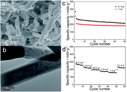
Mo6V9O40 nanorods were prepared through a sol–gel route followed by short-time calcination, and tested as cathode materials for lithium batteries. The Mo6V9O40 nanorods demonstrated good cyclic stability and rate performance at deep discharge (discharged to 1.5 V), which were attributed to the enhanced structural flexibility and the 1D structure.


Introduction

Searching for cathode materials of Li-based batteries with high energy densities has been a key mission in recent years.1,2 Among the various candidates, vanadium based cathode materials (such as LiV3O8 and V2O5) and molybdenum oxides have been intensively studied due to their high capacity, easy preparation, and low cost.3–9 Li ions could be reversibly intercalated/deintercalated into the inter layers of oxides such as V2O5 and MoO3. V2O5 presents a layered structure, which easily undergoes phase transitions from α-LixV2O5 (x < 0.01), ε-LixV2O5 (0.35 < x< 0.7), and ε-LixV2O5 to δ-LixV2O5 (x < 1), and then δ-LixV2O5 to γ-LixV2O5 (x > 1) when the discharge cutoff potential is set to 2 V (vs. Li/Li+).10 These phase transitions are reversible, and the layered structure is not destroyed. However, when discharged to 1.5 V, the transition from γ-LixV2O5 to ω-LixV2O5 (x > 2) occurs, which is irreversible and leads to poor electrochemical performance.11 The hybrid oxides, molybdenum–vanadium based oxides, have been reported to be more sustainable to over discharge (to 1.5 V), which include solid solution (V1−yMoy)2O5 (0 ≤ y ≤ 0.3) and Mo6V9O40.12–14 The molybdenum and vanadium ions are distributed disorderly in (V1−yMoy)2O5 and regularly in Mo6V9O40. Mo6V9O40 was reported as MoV2O8 initially, and the prepared MoV2O8 was invariably accompanied with V2O5 impurities according to the previous reports.15,16 Introduction of Mo to the structure increases the length of M–O bonds, which is more flexible for Li ion insertion/extraction.17 In addition, substituting Mo6+ for V5+ results in the presence of V4+ and increases the electronic conductivity.

Molybdenum and vanadium mixed oxides are usually prepared through solid state reactions above 600 °C with extremely long calcination time (over 50 h) in the previous reports.17,18 However, the long heating time at high temperatures degrades the morphology and results in large particles with several microns in diameter, which does not benefit the electrochemical performance and large scale production.18 In this work, Mo6V9O40 nanorods were prepared by a facile sol–gel method. The gel was firstly heated in Ar atmosphere by a two-step calcine process to get the precursor, in which vanadium and molybdenum elements were dispersed uniformly in excessive amorphous carbon. The Mo6V9O40 nanorods were prepared by caclining the obtained precursor in air, and the time for phase formation was reduced to 2 h. The preparation time was remarkably decreased. The Mo6V9O40 nanorods exhibited good cyclic stability and rate performance.

Experimental

Material preparation

The Mo6V9O40 samples were prepared by a sol–gel method described elsewhere with minor modifications.19,20 In brief, 0.0883 g ammonium molybdate tetrahydrate, 0.117 g ammonium metavanadate, 1 g citric acid, and 5 g urea were dissolved in 200 ml water–ethanol mixed solvent with agitation under 75 °C to form a homogenous solution. Here, the amount of ammonium metavanadate was excessive to promote the generation of Mo6V9O40. The color of the solution changed from orange to blue due to the reduction and complexation of V ions. After the excess solvent was evaporated, the formed gel was dried under 100 °C in air. The gel was preheated at 350 °C for 4 h and then calcined at 650 °C for 10 h in flowing argon. The obtained precursor was finally calcined in air under different temperatures to get Mo6V9O40 samples.

Material characterization

Powder X-ray diffraction (XRD) patterns were recorded on a D/MAX III diffractometer with Cu Kα radiation. Morphologies of the samples were observed on field emission scanning electron microscope (FESEM, JEOL-JSM7500) and transmission electron microscope (TEM, Tecnai G2 Spirit). The composition of the samples was confirmed by the energy dispersive X-ray spectroscopy (EDX) attached to the FESEM instrument.

Electrochemical tests

For the electrode preparation, Mo6V9O40 (80 wt%), acetylene black (10 wt%), and polyvinylidene fluoride (PVDF) binder (10 wt%) in N-methylpyrrolidone were mixed, and the obtained homogenous slurry was pasted on Al foil, followed by drying in vacuum at 110 °C. Coin cells (CR2025) were fabricated in an argon-filled glove box with lithium metal as the counter electrode, and LiPF6 (1 M) in ethylene carbonate/ethyl methyl carbonate/dimethyl carbonate (EC/EMC/DMC, 1[thin space (1/6-em)]:[thin space (1/6-em)]1[thin space (1/6-em)]:[thin space (1/6-em)]1 vol.%) as the electrolyte. Galvanostatic charge/discharge tests were performed on a Land CT2001 battery tester in the voltage range of 1.5–4 V at room temperature. Cyclic voltammogram (CV) tests were performed under a Zahner-Elektrik IM6e electrochemical workstation in the voltage range of 1.5–4 V at a scan rate of 0.1 mV s−1.

Results and discussion

To decrease the agglomeration of the Mo6V9O40 materials, the preparation temperature was optimized and the calcining time was limited to 2 h. The XRD patterns of the samples obtained at different temperatures are shown in Fig. 1. When calcined at 500 °C, the samples are composed of vanadium oxides and molybdenum oxides at low valence. The complete monoclinic Mo6V9O40 phase formed at 550 °C with the space group of C121 (JCPDS#74-1510), and the impurity could be indexed as V2O5. The Mo6V9O40 diffraction peaks are unchanged when calcined at higher temperatures. The SEM images of the samples obtained at different temperatures are shown in Fig. 2. The particles of the sample calcined at 500 °C are bulk and irregular. When calcined at 550 °C, the sample is composed of uniform nanorods with the diameters of ∼200 nm. The particle size increases obviously when the calcined temperature increased to 600 °C, and the cuboid structure is observed. The cuboid structure is more common when calcined at 650 °C, and the diameters increase to several microns. The particle size and morphology are very sensitive to the calcination temperature, and large particles block the Li ion diffusion. Therefore, the Mo6V9O40 sample calcinated at 550 °C was chosen for the following studies.
image file: c4ra16335d-f1.tif
Fig. 1 XRD patterns of the Mo6V9O40 samples prepared under different calcination temperatures (■ V2O5 impurity).

image file: c4ra16335d-f2.tif
Fig. 2 SEM images of the Mo6V9O40 samples under different calcination temperatures: (a) 500 °C, (b) 550 °C, (c) 600 °C, and (d) 650 °C.

The microstructures of the Mo6V9O40 sample calcinated at 550 °C are shown in Fig. 3. The Mo6V9O40 nanorods disperse consistently and the length is lower than 1 μm. The elemental mappings of the Mo6V9O40 nanorods are shown in Fig. S1 (ESI), and the Mo, V, and O elements are distributed homogeneously. According to the EDX result, the atomic ratio of Mo and V is close to 1[thin space (1/6-em)]:[thin space (1/6-em)]1.5. The HRTEM images in Fig. 3d and e further confirm the one-dimensional (1D) rod shape of the sample, which grows regularly. Fig. 3f shows the lattice of the nanorods in Fig. 3e. The interlayer spacing is 0.41 nm, determined as the (111) crystal planes.


image file: c4ra16335d-f3.tif
Fig. 3 (a and b) SEM images, (c) EDX spectrum, and (d–f) TEM images of the Mo6V9O40 nanorods calcined at 550 °C.

The electrochemical performances were evaluated in coin cells with Mo6V9O40 as the cathode and metallic lithium as the anode. The CV curves are shown in Fig. 4a. The position of the cathodic peaks in the first cycle is similar to that of V2O5 tested between 4.0 and 1.5 V, indicating the multiple phase transition.21 The peaks at 3.1, 2.9, 2.2, and 1.8 V correspond to the α–ε–δ–γ–ω phase transition of V2O5, although an additional peak at 2.65 V is observed, which may be due to the introduction of Mo. The small cathodic peak at ∼2.45 V is attributed to the V2O5 impurity due to the small phase transition, which was also found in previous reports.22,23 The cathodic peaks in the first cycle disappear in the following cycles, and two new pairs of anodic peaks and cathodic peaks emerge, which are stable in the subsequent cycles. Fig. 4b shows the galvanostatic charge/discharge curves at different cycles at the current density of 100 mA g−1. The initial discharge curve is also special, and the discharge plateaus are consistent with the CV curves. The discharge capacity is 369 mA h g−1, corresponding to the intercalation of 1.5 Li+ ions per metal ion. The ratio of the discharge capacity corresponding to the formation of ω phase (the 2 V plateau) is obviously larger than that of V2O5. The ω phase of Mo6V9O40 is formed not only by the intercalation of Li+ ions in the γ phase, but also in the δ phase and even ε phase.21 The ω phase of Mo6V9O40 is more reversible than the ω phase of V2O5, in which Li+ ions could be deintercalated partly.17 Then part of Li+ ions are deintercalated in the charge process because the phase transition blocks the diffusion of part Li+ ions. The charge/discharge curves keep stable and the Li+ ions are reversibly inserted/extracted in the following cycles.


image file: c4ra16335d-f4.tif
Fig. 4 (a) CV curves, (b) galvanostatic charge/discharge curves at different cycles at 100 mA g−1, (c) cyclic performance at 100 mA g−1 and 1 A g−1, and (d) cyclic performance at different rates of the Mo6V9O40 nanorods.

The cyclic performance of the Mo6V9O40 nanorods is shown in Fig. 4c. The discharge capacity at the 2nd cycle is 276.2 mA h g−1 at 100 mA g−1 and retains 214.8 mA h g−1 after 50 cycles. When tested at 1 A g−1, the discharge capacity at the 2nd cycle is 212 mA h g−1 and retains 181.8 mA h g−1 after 50 cycles. The Mo6V9O40 nanorods were also tested at other current densities (Fig. 4d). The discharge capacities are 239.4, 190.8, and 181.1 mA h g−1 at 0.3, 0.5, and 0.8 A g−1, respectively. When the current density returns to 100 mA g−1, the discharge capacity recovers to 230.4 mA h g−1. The Mo6V9O40 nanorods exhibited good cyclic stability and rate performance compared with the previous reports.17,24 Uchiyama et al. synthesized Mo6V9O40 by solid state reactions followed by quenching to room temperature, and the capacity retention was about 50% after 32 cycles.17 Delmas and Cognac-Auradou synthesized Mo6V9O40 by a long time calcination (70 h), and the capacity retention was about 68% after 50 cycles.24 Fig. S2 (ESI) shows the Coulombic efficiency when tested at 100 mA g−1. The Coulombic efficiency approaches 100% after the first cycle, indicating that no side reactions occur. The excellent performances at deep discharge are due to the enhanced structural flexibility resulting from the change in M–O bond lengths caused by substituting Mo for V. The 1D structure also facilitates the Li+ ion diffusion and enhances the rate performance.

Conclusions

In summary, we have developed a facile sol–gel method to synthesize Mo6V9O40 nanorods. The Mo6V9O40 nanorods are 200 nm in diameter, and their lengths are 500 nm to 1 μm. The electrochemical performances of the Mo6V9O40 nanorods as cathode materials for Li batteries were investigated and showed high electrochemical stability at deep discharge, with a reversible capacity up to 276.2 mA h g−1 at 100 mA g−1 and a high C-rate performance with a discharge capacity 212 mA h g−1 and retain 181.8 mA h g−1 after 50 cycles at 1 A g−1. The good cyclic stability and rate performance are attributed to the enhanced structural flexibility caused by substitution of Mo for V and the 1D structure, which allows for fast Li+ ion diffusion.

Acknowledgements

This work was supported by Tianjin Municipal Science and Technology Commission (14ZCZDGX00039), NSFC (21421001) and MOE Innovation Team (IRT13022) in China.

Notes and references

  1. B. Dunn, H. Kamath and J. M. Tarascon, Science, 2011, 334, 928 CrossRef CAS PubMed.
  2. M. Hu, X. Pang and Z. Zhou, J. Power Sources, 2013, 237, 229 CrossRef CAS PubMed.
  3. G. Yang, G. Wang and W. Hou, J. Phys. Chem. B, 2005, 109, 11186 CrossRef CAS PubMed.
  4. X. Chen, H. Zhu, Y.-C. Chen, Y. Shang, A. Cao, L. Hu and G. W. Rubloff, ACS Nano, 2012, 6, 7948 CrossRef CAS PubMed.
  5. A.-M. Cao, J.-S. Hu, H.-P. Liang and L.-J. Wan, Angew. Chem., Int. Ed., 2005, 44, 4391 CrossRef CAS PubMed.
  6. C. H. Han, M. Y. Yan, L. Q. Mai, X. C. Tian, L. Xu, X. Xu, Q. Y. An, Y. L. Zhao, X. Y. Ma and J. L. Xie, Nano Energy, 2013, 2, 916 CrossRef CAS PubMed.
  7. H. B. Wu, A. Pan, H. H. Hng and X. W. Lou, Adv. Funct. Mater., 2013, 23, 5669 CrossRef CAS.
  8. L. Q. Mai, B. Hu, W. Chen, Y. Y. Qi, C. S. Lao, R. S. Yang, Y. Dai and Z. L. Wang, Adv. Mater., 2007, 19, 3712 CrossRef CAS.
  9. K. Sakaushi, J. Thomas, S. Kaskel and J. Eckert, Chem. Mater., 2013, 25, 2557 CrossRef CAS.
  10. E. Uchaker, N. Zhou, Y. Li and G. Cao, J. Phys. Chem. C, 2013, 117, 1621 CAS.
  11. A. Sakunthala, M. V. Reddy, S. Selvasekarapandian, B. V. R. Chowdari and P. C. Selvin, Energy Environ. Sci., 2011, 4, 1712 CAS.
  12. P. Fiordiponti, M. Pasquali, G. Pistoia and F. Rodante, J. Power Sources, 1981, 7, 133 CrossRef.
  13. M. Pasquali, G. Pistoia and F. Rodante, J. Power Sources, 1981, 7, 145 CrossRef.
  14. A. Tranchant and R. Messina, J. Power Sources, 1988, 24, 85 CrossRef CAS.
  15. Y. Muranushi, T. Miura, T. Kishi and T. Nagai, J. Power Sources, 1987, 20, 187 CrossRef CAS.
  16. W. Kaveevivitchai and A. J. Jacobson, Chem. Mater., 2013, 25, 2708 CrossRef CAS.
  17. M. Uchiyama, S. Slane, E. Plichta and M. Salomon, J. Electrochem. Soc., 1989, 136, 36 CrossRef CAS PubMed.
  18. P. Fiordiponti, M. Pasquali, G. Pistoia and F. Rodante, J. Power Sources, 1981, 7, 133 CrossRef.
  19. L. Su, Z. Zhou and P. Shen, J. Phys. Chem. C, 2012, 116, 23974 CAS.
  20. M. Hu, Y. Tian, L. Su, J. Wei and Z. Zhou, ACS Appl. Mater. Interfaces, 2013, 5, 12185 CAS.
  21. X. Zhou, G. Wu, J. Wu, H. Yang, J. Wang, G. Gao, R. Cai and Q. Yan, J. Mater. Chem. A, 2013, 1, 15459 CAS.
  22. Y. N. Ko, Y. Chan Kang and S. B. Park, Nanoscale, 2013, 5, 8899 RSC.
  23. J. Shao, X. Li, Z. Wan, L. Zhang, Y. Ding, L. Zhang, Q. Qu and H. Zheng, ACS Appl. Mater. Interfaces, 2013, 5, 7671 CAS.
  24. C. Delmas and H. Cognac-Auradou, J. Power Sources, 1995, 54, 406 CrossRef CAS.

Footnote

Electronic supplementary information (ESI) available: Elemental mappings of Mo6V9O40 nanorods, and Coulombic efficiency cycled at 100 mA g−1. See DOI: 10.1039/c4ra16335d

This journal is © The Royal Society of Chemistry 2015