DOI:
10.1039/C4RA16261G
(Paper)
RSC Adv., 2015,
5, 18367-18374
Temperature induced gelation transition of a fumed silica/PEG shear thickening fluid
Received
12th December 2014
, Accepted 5th February 2015
First published on 5th February 2015
Abstract
The effect of temperature on the rheological behaviors of a shear thickening fluid (STF) prepared by dispersing fumed silica (SiO2) particles into polyethylene glycol (PEG) under mechanical stirring and ultrasonication was investigated using a rotational rheometer. Under steady shear, the system showed an obvious shear thickening behavior due to the formation of “hydroclusters” of SiO2 particles driven by hydrodynamic lubrication forces. The value of the critical shear rate at which the shear thickening begins grows monotonically with temperature. Dynamic temperature sweeps show that elevating the temperature induces a gelation transition of the SiO2/PEG system when the concentration of SiO2 exceeds a critical value, which is found to be lower for the system consisting of higher average molecular weight PEG. The gelation process also becomes more remarkable at a higher concentration of SiO2 particles. It is found that the temperature induced gelation of SiO2/PEG sol is essentially related to the disappearance of the solvation layer on the surface of SiO2 particles as well as the change of hydrogen bonds.
1. Introduction
A shear thickening fluid (STF) is a kind of colloidal dispersion whose viscosity increases dramatically when increasing the shear rate or applied stress.1–7 Shear thickening is a non-Newtonian flow behavior often observed in concentrated colloidal suspensions and is accompanied with a significant, discontinuous steep increase in viscosity when the applied shear rate is increased.8 The addition of colloidal particles to a liquid results in an increase in the viscosity and the fluid behaves as if it has an apparent yield stress. A critical yield stress must be applied to induce flow in a dispersion with high particle concentration. Beyond the critical stress, shear thinning occurs with the viscosity decreasing with increasing shear rate; at higher shear rate, shear thickening occurs and viscosity rises abruptly, sometimes discontinuously, once a critical shear stress is reached.9 After the removal of the impact stress or shear, STF recovers its original liquid state, exhibiting a good reversibility.
Due to the unique shear thickening behavior, STFs have attracted great attention in the field of personal protective materials.10–15 Recently, a new kind of bulletproof composite, i.e., liquid armor, soft and tough, has been produced by treating high performance fiber fabric with STF.11–13 Compared with traditional bulletproof equipment which is hard and heavy, the liquid armor is much softer and comfortable, and it becomes very tough instantaneously when suffering cutting of a sword or sudden impact of bullets, which greatly decreases the harm to the wearer. In this case, STF is the key point to achieve the unique properties of liquid armor.
The studies of STF system have focused mainly on two aspects: the shear thickening mechanism and rheological properties. As far as the shear thickening mechanism, much effort has been paid two main models. Hoffman2,3 used in situ light diffraction combined with shear rheology to elucidate micro-structural changes that during the onset of shear thickening in his pioneering studies. He concluded that the occurrence of shear-thickening behavior in concentrated dispersions at the critical shear rate corresponds to a transition from an easy flowing state where the particles are ordered into layers to a disordered state where this ordering is absent.2 This mechanism is generally called an order–disorder transition. Bossis and Brady16 and several other researchers17–22 demonstrated that the reversible shear-thickening behavior in concentrated colloidal suspensions was caused by hydrodynamic lubrication forces between the particles, which induced the formation of the non-equilibrium, self-organized microstructure that developed under strong flows, denoted as “hydroclusters”. The flow induced “hydroclusters” were then experimentally observed by rheo-optical23,24 and neutron scattering methods.25–28 For example, Kalman and Wagner28 developed a new method of flow-ultra small angle neutron scattering to probe the colloidal microstructure under steady flow conditions on length scales sufficient to elucidate the formation of hydroclusters. Their structural measurements confirmed that hydroclusters are fluctuations in the form of transient, compact clusters as opposed to large, cell-spanning, fractal-like aggregates. They also demonstrated that an order–disorder transition may accompany shear thickening even it was not necessary and that the shear-thickened state showed hydrocluster formation. These researches demonstrated that the “hydroclusters” mechanism was more appropriate and generalized to explain the shear thickening behavior. The rheological researches of STF usually focus on the performance of STF with stable or dynamic shear stress (or shear rate) is applied and the rheological properties have been reported to be influenced by particle size, surface charges, volume and dispersion state and properties of dispersion medium.29–34 Jiang et al.35 explored the effect of particle size and polymer length on the flow properties of composite melts. Their study showed that the potential of mean force experienced by the particles suspended in polymer melts was altered by particle size, and this effect was enhanced in high molecular weight polymer melt, and particles experienced weak attractions that extend beyond the extent of bound polymer layers as polymer molecular weight grew even below the entanglement molecular weight. They showed that the linear rheology, yielding behavior, and shear thickening response of dense composites varied with Rg/Dc (Rg and Dc are polymer radius of gyration and particle diameter, respectively), with volume exclusion glass formation observed at low Rg/Dc and gelation at high Rg/Dc, and with yielding and shear thickening properties changed by Rg and Dc independently. However, most of previous studies focused on the rheological properties at room temperature, and very limited attention has been paid to the effect of temperature on STF, which might easily happen during processing or practical applications. Thus it is important to obtain insight into the effect of external temperature and the temperature change on the properties and microstructure of STF system.
A lot of studies have shown that STF can be prepared by dispersing fumed silica (SiO2) particles in solvents like polyethylene glycol (PEG), polypropylene glycol (PPG), is a kind of STF.31,32,34,36–39 Wagner et al. have shown that the rheology of concentrated colloidal suspensions is extremely sensitive to interparticle forces and nanoscopic characteristics of colloidal surfaces. Consequently, rheology is a valuable tool for characterizing forces acting between colloidal particles on the nanoscale.40 In this work, with the help of high-speed mechanical stirring and ultrasonication, fumed SiO2 particles with different concentration were dispersed in PEG solvent with different molecular weight to prepare fumed SiO2/PEG sols. Rheological studies, consisting of stable and dynamic shear sweeps, combined with transmission electron microscope (TEM) and Fourier transform infrared spectrometry (FTIR) were employed to investigate the influence of factors like temperature, solvent property and particle concentration on shear thickening behavior and rheological properties of the sols.
2. Experimental
2.1. Materials and sample preparation
The colloidal nanoparticle employed here was fumed silica particles whose native properties have been studied in detail by Gun'ko and co-workers.41–43 The fumed SiO2 particles are synthesized by high-temperature hydrolysis of tetrachlorosilane in a hydrogen/oxygen flame and display hydrophilic characteristics due to the abundance of silanol groups on their surfaces. The fumed SiO2 used here is Aerosil A200 (Evonik Degussa Corporation, Germany) with a specific surface area (BET) of 200 m2 g−1. The fumed silica particles were dried for 12 h in a vacuum oven at 120 °C prior to use. Two types of PEG were used in this study: PEG200 with average molecular weight ranged from 180 to 220 and PEG400 with average molecular weight ranged from 380 to 420.
The sols were prepared by adding fumed silica particles to an exact amount of PEG. To get a good dispersion of fumed SiO2 particles, the sols were firstly mechanically stirred for 8 h and subsequently placed in an ultrasonic bath (100 W) for 2 h at room temperature. Finally, the obtained sols were placed in vacuum oven at 25 °C for 10 h to remove any air bubbles formed during mixing. The information of all the samples is shown in Table 1.
Table 1 Mass fraction and volume fraction of the SiO2/PEG suspensions. The volume fraction, ϕc, is calculated according to the method proposed by Anderson44 by using the mass fraction, the filled melt density ρT and a particle density, ρc
Sample |
Concentration of SiO2 |
SiO2/PEG200 |
ϕm (wt%) |
20 |
25 |
30 |
40 |
ϕc (vol%) |
15.0 |
18.0 |
23.2 |
31.9 |
SiO2/PEG400 |
ϕm (wt%) |
5 |
10 |
15 |
20 |
ϕc (vol%) |
3.6 |
7.3 |
11.1 |
15.0 |
2.2. Morphology characterization of fumed SiO2 particles
Transmission electron microscopy (TEM, Tecnai G2 F20 S-TWIN, FEI Co., USA) was used to reveal the micro-structure of fumed SiO2 particles. Before TEM observation, the dried fumed SiO2 was dispersed in ethyl alcohol to prepare a dilute solution. The solution was treated with ultrasonic for 2 h to get a good dispersion. Then the fumed SiO2 particles in the dilute solution were collected by a copper net and after complete volatilization of the ethyl alcohol, they were observed at an accelerating voltage of 200 kV. The particle/cluster size of fumed SiO2 particles was also analyzed by using a Nano Particle Analyser. The prepared SiO2/PEG200 sol (20 wt%) and that after heating process were diluted to a low concentration of 0.2 mg mL−1 and analyzed at 25 °C.
2.3. Fourier transform infrared spectroscopy (FT-IR)
FT-IR spectra were obtained with a Nicolet 6700 FT-IR spectrometer (Thermo scientific, co., USA) to identify the organic groups in pure fumed SiO2 and the prepared PEG/SiO2 sol. All the testing was conducted in attenuated total transmission mode and each spectrum was recorded from 600 to 4000 cm−1 by averaging 16 scans at a resolution of 2 cm−1.
2.4. Rheological tests
Rheological tests were carried out by using a rotational rheometer (AR2000EX, TA instruments, USA) with parallel plates (25 mm in diameter). The rheometer is equipped with a Peltier control system that provides accurate control of temperature. For the sample loading, the sample was sucked up carefully and slowly from a plastic tube by a pipette which could accurately control the sample volume (a sample volume of 0.420 mL was chosen in this work). Then, the speed and the force of the compression process to produce an appropriate gap (0.650 mm) for the dynamic rheological tests were strictly controlled by the rheometer.
The steady shear test was performed for all samples with the shear rate ranging from 5 to 10000 s−1 at 25 °C. For SiO2/PEG200 system, steady shear test was also performed at 10, 30 and 60 °C to examine the effect of temperature on the shear thickening behavior of the sols. Dynamic temperature sweep was performed at a fixed frequency of 1 rad s−1 and a fixed strain of 0.5% to examine the structure changing of the fumed SiO2 with temperature. During testing, the sample was first heated from 5 °C to 80 °C at a rate of 5 °C min−1 and then cooled to 5 °C at the same rate. For the samples before and after temperature sweep, dynamic frequency sweep was performed from 0.01 to 100 Hz s−1 at a strain of 0.5%.
3. Results and discussion
3.1. Microstructure of fumed SiO2 particles
According to the TEM image shown in Fig. 1a, pure fumed SiO2 particles form large aggregates and present a branched chain-like structure, which is usually called nanoparticle chain aggregates (NCA).45–49 The results characterized by using a Nano Particle Analyzer show that the NCA size in SiO2/PEG200 sol (without heating) is mostly in the range of 400–500 nm. Fumed silica particles are synthesized by high-temperature hydrolysis of tetrachlorosilane in a hydrogen/oxygen flame. In this process, proto-particles directly formed during chemical reaction collide and coalesce to give primary particles (5–30 nm), and then the collision, sticking, and partial fusion of these primary particles result in the formation of stable fractal aggregates (i.e., NCA) in the range from 100 to 500 nm, which corresponds well with the results. The fumed SiO2 NCA is stable and hard to be damaged.33,34 So when fumed SiO2 particles are employed as fillers, NCA rather than single particle is the basic unit in the matrix.
|
| Fig. 1 (a) Typical TEM image of the chain-like structure and (b) particle/cluster size distribution of fumed silica aggregates. | |
3.2. FT-IR characterization
FT-IR spectra of pure fumed SiO2 and the STF system of SiO2/PEG are shown in Fig. 2 to display the change in hydrogen bonds. For pure fumed SiO2, the remarkable absorption peak around 3432 cm−1 results from the silanol groups (Si–OH) on the surface of SiO2 and the antisymmetric hydrogen bond of the bond water. For PEG/SiO2 system, however, the hydroxyl peak shifts to a lower wavenumber of 3416 cm−1, indicating the existence of hydrogen bond between the PEG molecules and the silanol groups. Further, the peak at 3416 cm−1 is much stronger than that at 3432 cm−1, indicating that the hydrogen bond in SiO2/PEG system is much stronger, which can guarantee the stable dispersion of fumed SiO2 particles in the sol.
|
| Fig. 2 FTIR spectra of pure fumed silica and the SiO2/PEG sol (the concentration of fumed SiO2 A200 is 20 wt%). | |
3.3. Shear thickening behavior of SiO2/PEG sol
Fig. 3a shows the steady-shear viscosity of SiO2/PEG200 sols as a function of shear rate with the concentration of fumed SiO2 being 20, 25, 30 and 35 wt%, respectively. It is found that all the sols, irrespective of the concentration of fumed SiO2, show a similar rheological behavior: the viscosity decreases with increasing shear rate at low shear rate, exhibiting a shear thinning behavior; when the shear rate reaches a critical value, the viscosity increases dramatically to a value of several orders of magnitude higher, exhibiting a typical shear thickening behavior.
|
| Fig. 3 Steady-state viscosity for SiO2/PEG sols at various weight concentration of fumed SiO2 nanoparticle: (a) SiO2/PEG200; (b) SiO2/PEG400. | |
The mechanism of this shear thickening behavior can be explained by the “hydroclusters” theory proposed by Bossis and Brady based on Stokesian hydrodynamic model.15,16 Fig. 4 schematically presents the formation of “hydroclusters” in fumed SiO2/PEG sol. Firstly, owing to the existence of terminal hydroxyl on PEG molecules and the abundant silanol groups on the surface of fumed SiO2, it is easy to form hydrogen bond between them. The PEG molecules absorbed on the surface of SiO2 by hydrogen bond act as a solvation layer, which hinders the interaction between the fumed SiO2 particles and thus stabilizes the dispersion of fumed SiO2 in sol. As shown in Fig. 4a, at low shear rate, even though the microstructure is slightly damaged, it can recover quickly by Brownian motion of particles. As a result, the viscosity is slightly changed. With increasing shear rate, the structure loses its recoverability and the damage increases, and the interaction between the fumed SiO2 particles decreases, leading to that some independent SiO2 aggregates appear and the viscosity of the system decreases further, exhibiting shear thinning behavior (just as shown in Fig. 4b). With further increasing shear rate, hydrodynamic lubrication forces dominate in the system and the structure is severely damaged, resulting in more SiO2 aggregates. When the shear rate exceeds a critical value, driven by hydrodynamic lubrication forces, the small fumed SiO2 aggregates collide and form “hydroclusters”. The big “hydroclusters” can behave like a wall and significantly hinder the flow of the fluid (as shown in Fig. 4c). As a result, the viscosity of system shows a steep increase.
|
| Fig. 4 The mechanism of shear thickening. | |
Fig. 3b shows the steady-shear viscosity of SiO2/PEG400 sols as a function of shear rate with the concentration of fumed SiO2 being 5, 10, 15 and 20 wt%, respectively. It is found that the SiO2/PEG400 system shows a similar behavior to that of SiO2/PEG200 system. It is also found that in both systems, the sol with higher concentration of SiO2 shows stronger shear thickening behavior with a steeper increase of viscosity at a lower critical shear rate. This is because with increasing concentration of fumed SiO2, the distance between the particles decreases and more “hydroclusters” with a large size can form at lower shear rate, which greatly enhance the shear thickening behavior. What's more, it is found that SiO2/PEG400 system displayed remarkable shear thickening behavior at a SiO2 concentration of 20 wt% while SiO2/PEG200 system did not at the same SiO2 concentration. Considering that PEG400 has a higher molecular weight, the number of terminal hydroxyl for PEG400 is less than that of PEG200 at the same weight or volume. In this case, the hydrogen bond number between fumed SiO2 and PEG400 molecules is less and the interactions is relatively weak, so the fumed SiO2 particles can get away from the constraint of molecules easily and participate in the formation of “hydroclusters”.
3.4. Effect of temperature on the shear thickening behavior of SiO2/PEG sols
Fig. 5 shows the steady-shear viscosity of SiO2/PEG200 sols with a concentration of fumed SiO2 of 25 wt% as a function of shear rate at 10, 30 and 60 °C, respectively. It is obvious that the SiO2/PEG200 sols displayed shear thickening behavior at these temperatures. However, the viscosity of the sols at high temperature is much lower than that at lower temperature. The reason may lie in two aspects: firstly, with increasing temperature, the strength of hydrogen bond between fumed SiO2 and solvent decreases; secondly, at higher temperature, the Brownian motion of the particles is enhanced, leading to a much disordered structure. According to Fig. 5, the shear rate at which shear thickening happens, namely, the critical shear rate, increases with increasing temperature. This is because shear thickening happens only when the hydrodynamic lubrication forces overcome the repulsive forces between the particles and induce the formation of “hydroclusters”, however, the repulsive forces also increase with temperature,47 as a result, a larger shear rate is needed to induce the formation of “hydroclusters” at higher temperature.
|
| Fig. 5 Steady-state viscosity curves for SiO2/PEG200 sol (at the particle concentration of 25 wt%) at various temperature (10 °C, 30 °C and 60 °C). | |
3.5. Temperature induced gelation of SiO2/PEG200 sols
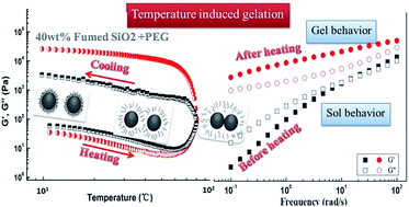
Fig. 6 shows the temperature dependence of storage modulus (G′) and loss modulus (G′′) for SiO2/PEG200 sols with the concentration of SiO2 of 40 wt%. With increasing temperature, G′ and G′′ decrease slowly at first but increase substantially when the temperature exceeds 60 °C, the G′ and G′′ values are about 104 Pa at 80 °C, which are much higher than the initial values at 10 °C (about 102 Pa). When temperature decreases from 80 °C, the G′ value is higher than G′′, exhibiting a solid-like behavior.
|
| Fig. 6 Temperature sweep for the SiO2/PEG200 sol at a particle concentration of 40 wt%. The experiment was conducted at a strain amplitude of 0.2% and a constant frequency of 1 rad s−1. Test temperature was firstly heated up from 10 °C to 80 °C at 5 °C min−1, and then cooled down immediately from 80 °C to 10 °C at 5 °C min−1. | |
The modulus variation of several orders of magnitude during temperature sweep indicates that the structure of SiO2/PEG200 sol is changed and induced by the elevated temperature. To further verify the structure change, dynamic frequency sweep was performed for samples before and after temperature sweep. As shown in Fig. 7, before heating, the G′ of the system is less than G′′ and both G′ and G′′ increase with increasing frequency, showing frequency dependence, which is the typical structure characteristics of sol. After heating, however, G′ of the system is larger than G′′ and both G′ and G′′ show frequency independence, showing a typical structure characteristics of gel.38,50,51 The results definitely demonstrate than elevated temperature can induce a transition from sol to gel for SiO2/PEG dispersion system, that is, steadily dispersed particles formed a three-dimensional network structure.
|
| Fig. 7 Modulus (G′ and G′′, Pa) as a function of frequency (rad s−1) for the SiO2/PEG400 sol before and after heating with the particle concentration is 40 wt%. The frequency sweep was conducted at a strain amplitude of 0.2%. | |
As previously mentioned, the formation of fumed SiO2/PEG sol depends on the solvation layer on the surface of SiO2, which in turn depends on the hydrogen bond between fumed SiO2 particles and PEG molecules. So the gelation of the system means that the hindrance effect of the solvation layers is weakened or disappears since only by which the particles can collide and link up by the silanol groups and further form a three-dimensional network structure, which can be demonstrated by the online FT-IR measurement. For fumed SiO2 dispersion, the peak around 3400 cm−1 is the characteristic absorption peak of hydrogen bond. The online FT-IR spectra of fumed SiO2/PEG sol during temperature sweep are shown in Fig. 8. During heating the characteristic peak of hydrogen bond at 3415 cm−1 is unchanged before 45 °C, however, the peak intensity decreases gradually, which indicate that the number of hydrogen bonds between fumed SiO2 particles and PEG molecules is decreasing, i.e., the solvation layer on the surface of fumed SiO2 particle is disappearing. When temperature reaches 65 °C, the characteristic peak of hydrogen bond shifts towards a lower wave number value of 3396 cm−1. The redshift phenomenon means that the original hydrogen bond pattern is changed. Considering that the modulus of the system begins to increase at 65 °C, it is easy to infer that a new kind of hydrogen bond is formed between the fumed SiO2 particles. During cooling process, the hydrogen bond peak continues to shift to lower wavenumbers and finally reaches a stable value of 3381 cm−1, and at the same time, the peak intensity increases gradually with decreasing temperature, indicating that the number of hydrogen bond is increasing, which corresponds well with the modulus increase of the system during cooling. All of these indicate that the formed network structure during heating process is perfected and stabilized during cooling process. As a result, the gelation process is irreversible.
|
| Fig. 8 FT-IR spectra of the SiO2/PEG sols (with 40 wt% fumed SiO2) before and after thermal treatment in the spectrometer equipped with a temperature controller. The test temperature was firstly heated up from 10 to 80 °C at 5 °C min−1 and then cooled down immediately from 80 to 10 °C at the same rate. | |
In conclusion, based on “hydroclusters” theory, in the gelation transition of fumed SiO2/PEG sol, temperature plays a similar role as that of hydrodynamic lubrication forces in the shear thickening process. Fig. 9 schematically shows the structure change of SiO2/PEG sol with temperature. Initially, both fumed SiO2 particles and PEG molecules have strong tendency to form hydrogen bond, leading to that the particles are covered by a solvation layer, which hinders the interaction between particles and facilitates the dispersion of particles in the solvent, as shown in Fig. 9a. With temperature increasing, the hydrogen bond between particles and solvents is weakened and the mobility of PEG molecules is increased, leading to that the solvation layer on the surface of particles is weakened, as shown in Fig. 9b. With the temperature further increasing, the solvation layer covered the particles gradually disappear and the particles gradually get rid of the interactions between particles and solvents. With enhanced Brownian motion opportunity to collide, the particles form hydrogen bonds owing to the abundant silanol groups on their surface and form “hydroclusters”, as shown in Fig. 9c. The formed “hydroclusters” join up and form a network structure, that is, gel. During cooling, since the formation of hydrogen bond between SiO2 particles, PEG molecules cannot form hydrogen bond with SiO2 particles and further cover the particles by solvation layer any more. On the contrary, the hydrogen bond between the particles is enhanced with temperature decreasing, which strengthens the network structure of gel and increases the modulus of the gel. Fig. 1b also shows that after the particle/cluster size is greatly enhanced after the heating process due to the formation of particle network structure.
|
| Fig. 9 The schematic mechanism representation of temperature-induced structural transitions in the SiO2/PEG sol. | |
3.6. Effect of particle concentration on the gelation of fumed SiO2/PEG sol
Fig. 10 shows the temperature dependence of G′ for SiO2/PEG200 sols with the concentrations of SiO2 particles of 20, 25 and 30 wt%, respectively. Similar to Fig. 6, G′ of all the samples decrease in the beginning of heating process. However, with further heating, G′ decreases monotonically with temperature in the whole heating process for the sample with 20 wt% fumed SiO2; for the samples with 25 wt% and 30 wt% fumed SiO2, further increasing temperature will induce an increase of the G′ which is due to the gelation of the SiO2/PEG sol. During cooling, the cooling curve of the sample with 20 wt% fumed SiO2 coincides with the heating curve; for the sample with 25 wt% fumed SiO2, G′ increases with decreasing temperature and gradually deviates from the heating curve; for the sample with 30 wt% fumed SiO2, a similar trend to sample with 25 wt% fumed SiO2 is observed but with a much greater increase of G′. The results indicate that elevated temperature can induce the gelation of fumed SiO2/PEG sol only when the concentration of fumed SiO2 reaches a critical value. The reason may lie in two aspects: firstly, at a low concentration of fumed SiO2 particles, every single SiO2 particle may face more PEG molecules and form more hydrogen bonds, the solvation layer on the surface of particle is thick and as a result, it is hard for the particles to get rid of the constraint of PEG molecules during heating; secondly, at a low concentration, the distance between the particles is big, even if the particles get rid of the constraint of PEG molecules, it is hard for them to collide, link up and form a network structure. So, enough fumed SiO2 particles are needed in fumed SiO2/PEG sol with the purpose to induce gelation during heating, and with a larger fumed SiO2 concentration, more particles can link up and form a denser network structure, showing a more significant gelation.
|
| Fig. 10 Temperature sweep for SiO2/PEG200 sols at various particle concentration (20, 25 and 30 wt%). The experiment was conducted at a strain amplitude of 0.2% and a constant frequency of 1 rad s−1. Test temperature was firstly heated up from 10 °C to 80 °C at 5 °C min−1, and then cooled down immediately from 80 °C to 10 °C at 5 °C min−1. | |
3.7. Effect of molecular weight of PEG on the gelation of fumed SiO2/PEG sol
Fig. 11 shows the temperature dependence of G′ and G′′ for SiO2/PEG200 and SiO2/PEG400 sols with the concentration of SiO2 particles of 10 wt%. By comparing Fig. 11a and b, it is found that at a low SiO2 particle concentration of 10 wt%, G′ shows temperature independence when heating and the cooling curve coincides with the heating curve for SiO2/PEG200 sol; for SiO2/PEG400 sol, however, gelation occurs during heating. For these two kinds of sols with the same concentration of SiO2, the mass of PEG solvent is same, so PEG400 based sol has less PEG molecules and less terminal hydroxyls due to the higher molecular weight. As a result, the hydrogen bond between the PEG molecules and SiO2 particles is relatively weak and the solvation layer on the surface of SiO2 particles is thinner. This can be proved by the FT-IR spectra in Fig. 12. The intensity of hydrogen bond absorption peak at 3419 cm−1 for SiO2/PEG400 is obviously smaller than the intensity of hydrogen bond absorption peak at 3415 cm−1 for SiO2/PEG400, indicating a weaker hydrogen bond in SiO2/PEG400 sol. So during heating, the particles in SiO2/PEG200 sol cannot get rid of the constraint of PEG molecules due to the strong hydrogen bond at a low particle concentration; for SiO2/PEG400 sol, the hydrogen bond is weak, so it is easy for the particles to get rid of the constraint of PEG molecules by enhanced thermal motion during heating and then gelation happens.
|
| Fig. 11 Temperature sweep for the SiO2/PEG sols at the particle concentration of 10 wt%: (a) SiO2/PEG200; (b) SiO2/PEG400. The experiment was conducted at a strain amplitude of 0.2% and a constant frequency of 1 rad s−1. Test temperature firstly heated up from 10 °C to 80 °C at 5 °C min−1, and then cooled down immediately from 80 °C to 10 °C at 5°C min−1. | |
|
| Fig. 12 FTIR spectra of pure fumed silica and the SiO2/PEG (200 and 400) sols (the concentration of fumed SiO2 is 10 wt%). | |
4. Conclusions
The shear thickening behavior of SiO2/PEG sols was studied and the effect of temperature on the structure evolution was evaluated. The fumed SiO2 particles present a branched chain-like structure and contain abundant of silanol groups on the surface, and when dispersed in PEG solvent, a stabled sol with low viscosity is formed. Steady shear measurement showed that SiO2/PEG sol can perform obvious shear thickening behavior due to the formation of “hydroclusters” driven by hydrodynamic lubrication forces. The critical temperature at which shear thickening happened grew monotonically with increasing temperature. Dynamic temperature sweep showed that elevated temperature could induce the gelation transition of fumed SiO2/PEG sol and temperature played a similar role as that of hydrodynamic lubrication forces played in inducing shear thickening. It was showed that the gelation process of SiO2/PEG sol was essentially related to the disappearance of the solvation layer on the surface of particles as well as the change of hydrogen bond. Further investigation showed that elevated temperature could induce the gelation transition only when the concentration of fumed SiO2 reached a critical value, which was found to be lower for the system consisting of higher average molecular weight of PEG.
Acknowledgements
This work was supported by National Natural Science Foundation of China (NNSFC grants 51422305 and 51421061), Major State Basic Research Development Program of China (973 program) (grant no. 2012CB025902), the Innovation Team Program of Science & Technology Department of Sichuan Province (grant 2013TD0013) and State Key Laboratory of Polymer Materials Engineering (grant no. sklpme2014-2-02).
References
- D. I. Lee and A. S. Reder, TAPPI Coat. Conf., Proc., 1972, 201–231 Search PubMed.
- R. L. Hoffman, Trans. Soc. Rheol., 1972, 16, 155–173 CrossRef CAS.
- R. L. Hoffman, J. Colloid Interface Sci., 1974, 46, 491–506 CrossRef CAS.
- H. A. Barnes, J. Rheol., 1989, 33, 329–366 CrossRef CAS.
- W. H. Boersma, J. Laven and H. N. Stein, AIChE J., 1990, 36, 321–332 CrossRef CAS.
- R. L. Hoffman, J. Rheol., 1997, 42, 111–123 CrossRef.
- R. Helber, F. Doncker and R. Bung, J. Sound Vib., 1990, 138, 47–57 CrossRef.
- L. Chang, K. Friedrich, A. K. Schlarb, R. Tanner and L. Ye, J. Mater. Sci., 2011, 46, 339–346 CrossRef CAS PubMed.
- N. J. Wagner and J. F. Brady, Phys. Today, 2009, 62, 27–3210 CrossRef CAS PubMed.
- X. Y. Feng, S. K. Li, Y. Wang, Y. C. Wang and J. X. Liu, Mater. Des., 2014, 64, 456–461 CrossRef CAS PubMed.
- R. Helber, F. Doncker and R. Bung, J. Sound Vib., 1990, 138, 47–57 CrossRef.
- H. M. Laun, R. Bung and F. Schmidt, J. Rheol., 1991, 35, 999–1034 CrossRef CAS.
- Y. S. Lee, E. D. Wetzel and N. J. Wanger, J. Mater. Sci., 2003, 38, 2825–2833 CrossRef CAS.
- E. D. Wetzel, Y. S. Lee, R. G. Egres, K. M. Kirkwood, J. E. Kirkwood and N. J. Wagner, AIP Conf. Proc., 2004, 712, 288–293 CrossRef CAS PubMed.
- T. J. Kang, K. H. Hong and M. R. Yoo, Fibers Polym., 2010, 11, 719–724 CrossRef CAS.
- G. Bossis and J. F. Brady, J. Chem. Phys., 1989, 91, 1866–1874 CrossRef CAS PubMed.
- W. H. Boersma, J. Laven and H. N. Stein, J. Colloid Interface Sci., 1992, 149, 10–22 CrossRef CAS.
- R. S. Farr, J. R. Melrose and R. C. Ball, Phys. Rev. E: Stat. Phys., Plasmas, Fluids, Relat. Interdiscip. Top., 1997, 55, 7203–7211 CrossRef CAS.
- H. Watanabe, M. L. Yao, K. Osaki, T. Shikata, H. Niwa, Y. Morishima, N. P. Balsara and H. Wang, Rheol. Acta, 1998, 37, 1–6 CrossRef CAS.
- D. R. Foss and J. F. Brady, J. Fluid Mech., 2000, 407, 167–220 CrossRef CAS.
- A. A. Catherall, J. R. Melrose and R. C. Ball, J. Rheol., 2000, 44, 1–25 CrossRef CAS.
- X. Cheng, J. H. McCoy, J. H. Israelachvili and I. Cohen, Science, 2011, 333, 1276–1279 CrossRef CAS PubMed.
- P. Dhaene, J. Mewis and G. G. Fuller, J. Colloid Interface Sci., 1993, 156, 350–358 CrossRef CAS.
- J. W. Bender and N. J. Wagner, J. Colloid Interface Sci., 1995, 172, 171–184 CrossRef CAS.
- J. Bender and N. J. Wagner, J. Rheol., 1996, 40, 899–916 CrossRef CAS.
- M. C. Newstein, H. Wang, N. P. Balsara, A. A. Lefebvre, Y. Shnidman, H. Watanabe, K. Osaki, T. Shikata, H. Niwa and Y. Morishima, J. Chem. Phys., 1999, 111, 4827–4838 Search PubMed.
- J. Vermant and M. J. Solomon, J. Phys.: Condens. Matter, 2005, 17, R187–R216 CrossRef CAS.
- D. P. Kalman and N. J. Wagner, Rheol. Acta, 2009, 48, 897–908 CrossRef CAS PubMed.
- V. B. C. Tan, T. E. Tay and W. K. Teo, Int. J. Solids Struct., 2005, 42, 1561–1576 CrossRef PubMed.
- T. J. Kang, C. Y. Kim and K. H. Hong, J. Appl. Polym. Sci., 2012, 124, 1534–1541 CrossRef CAS.
- F. J. Galindo-Rosales, F. J. Rubio-Hernández and J. F. Velázquez-Navarro, Rheol. Acta, 2009, 48, 699–708 CrossRef CAS PubMed.
- K. J. Yu, H. J. Cao, K. Qian, X. F. Sha and Y. P. Chen, J. Nanopart. Res., 2012, 14, 747(9) Search PubMed.
- N. C. Crawford, L. B. Popp, K. E. Johns, L. M. Caire, B. N. Peterson and M. W. Liberatore, J. Colloid Interface Sci., 2013, 396, 83–89 CrossRef CAS PubMed.
- W. Q. Jiang, F. Ye, Q. Y. He, X. L. Gong, J. B. Feng, L. Lu and S. H. Xuan, J. Colloid Interface Sci., 2014, 413, 8–16 CrossRef CAS PubMed.
- T. Jiang and C. F. Zukoski, Macromolecules, 2012, 45, 9791–9803 CrossRef CAS.
- S. R. Raghavan and S. A. Khan, J. Colloid Interface Sci., 1997, 185, 57–67 CrossRef CAS.
- F. Yziquel, P. J. Carreau and P. A. Tanguy, Rheol. Acta, 1999, 38, 14–25 CrossRef CAS.
- S. R. Raghavan, H. J. Walls and S. A. Khan, Langmuir, 2000, 16, 7920–7930 CrossRef CAS.
- M. Kamibayashi, H. Ogura and Y. Otsubo, J. Colloid Interface Sci., 2008, 321, 294–301 CrossRef CAS PubMed.
- N. J. Wagner and J. W. Bender, MRS Bull., 2004, 29, 100–106 CrossRef CAS.
- V. M. Gun'ko, I. F. Mironyuk, V. I. Zarko, V. V. Turov, E. F. Voronin, E. M. Pakhlov, E. V. Goncharuk, R. Leboda, J. Skubiszewska-Zieba, W. Janusz, S. Chibowski, Y. N. Levchuk and A. V. Klyuevaz, J. Colloid Interface Sci., 2001, 242, 90–103 CrossRef.
- V. M. Gun'ko, V. I. Zarko, E. F. Voronin, V. V. Turov, I. F. Mironyuk, I. I. Gerashchenko, E. V. Goncharuk, E. M. Pakhlov, N. V. Guzenko, R. Leboda, J. Skubiszewska-Zieba, W. Janusz, S. Chibowski, Y. N. Levchuk and A. V. Klyuevaz, Langmuir, 2002, 18, 581–596 CrossRef.
- V. M. Gun'ko, I. F. Mironyuk, V. I. Zarko, E. F. Voronin, V. V. Turov, E. M. Pakhlov, E. V. Goncharuk, Y. M. Nychiporuk, N. N. Vlasova, P. P. Gorbik, O. A. Mishchuk, A. A. Chuiko, T. V. Kulik, B. B. Palyanytsya, S. V. Pakhovchishin, J. Skubiszewska-Zieba, W. Janusz, A. V. Turov and R. Leboda, J. Colloid Interface Sci., 2005, 289, 427–445 CrossRef PubMed.
- B. J. Anderson and C. F. Zukoski, Macromolecules, 2008, 41, 9326–9334 CrossRef CAS.
- S. K. Friedlander, H. D. Jang and K. H. Ryu, Appl. Phys. Lett., 1998, 72, 173–175 CrossRef CAS PubMed.
- K. Ogawa, T. Vogt, M. Ullmann, S. Johnson and S. K. Friedlander, J. Appl. Phys., 2000, 87, 63–73 CrossRef CAS PubMed.
- Y. J. Suh, M. Ullmann, S. K. Friedlander and K. Y. Park, J. Phys. Chem. B, 2001, 105, 11796–11799 CrossRef CAS.
- W. Z. Rong, A. E. Pelling, A. Ryan, J. K. Gimzewski and S. K. Friedlander, Nano Lett., 2004, 4, 2287–2292 CrossRef CAS.
- R. Bandyopadhyaya, W. Z. Rong and S. K. Friedlander, Chem. Mater., 2004, 16, 3147–3154 CrossRef CAS.
- C. Fischer, S. A. Braun, P. E. Bourban, V. Michaud, C. J. G. Plummer and J. A. E. Manson, Smart Mater. Struct., 2006, 15, 1467 CrossRef.
- S. A. Khan and N. J. Zoeller, J. Rheol., 1993, 37, 1225–1235 CrossRef CAS.
|
This journal is © The Royal Society of Chemistry 2015 |
Click here to see how this site uses Cookies. View our privacy policy here.