 Open Access Article
Creative Commons Attribution 3.0 Unported Licence
Multi-stacked PDMS-based triboelectric generators with conductive textile for efficient energy harvesting
Yeong Hwan Ko,
Goli Nagaraju and
Jae Su Yu*
Department of Electronics and Radio Engineering, Institute for Laser Engineering, Kyung Hee University, 1 Seocheon-dong, Giheung-gu, Yongin-si, Gyeonggi-do 446-701, Republic of Korea. E-mail: jsyu@khu.ac.kr
First published on 4th December 2014
Abstract
We report triboelectric generators with multi-stacked layers of polydimethylsiloxane (PDMS) coated conductive textile (CT), and bare CT, fabricated by a simple and cost-effective methodology. Because PDMS is entirely covered over the upper and bottom surfaces of the CT substrate, both sides are utilized for the friction area of triboelectric charge generation, and the embedded CT can be used as an electrode. The bare CT, which is flexible and durable, also acts as a triboelectric material by rubbing the PDMS as well as an electrode. For a single-layer triboelectric generator, the averaged output voltage/current density of 8.12 V/25.77 nA cm−2 were observed under the external pushing forces of 3.5–4 kgf during footsteps test. The multi-stacked triboelectric generators were prepared by overlapping the PDMS coated CTs and bare CTs repeatedly. Under the same test conditions, the output voltage/current density of the triple-stacked device was considerably increased, up to 2.88/2.45 times, because the overlapped CT and PDMS layers could be uniformly pressed with the increased friction area. The external load dependent output power of the multi-stacked triboelectric generators was also investigated.
Introduction
Energy harvesting has been considered as a promising green technology to produce energy from various ambient mechanical vibrations and motions,1–3 which can be expected to realize self-powered mobile and wearable electronic devices. In recent years, triboelectric generators have attracted great attention in energy harvesting because they exhibit a high output power together with simple and flexible device structures.4–6 Typically, triboelectric generators are facilely prepared by closely separating two different triboelectric polymers and soft materials (e.g., polydimethylsiloxane (PDMS), polyester, or Kapton), which are in contact with each electronic conductive layer as an electrode.7,8 When external mechanical forces are applied to the triboelectric generators, electronic charges are generated by touching and rubbing the two polymer surfaces together. Thus, the charge flow is repeatedly created under triboelectric potential by subsequent cycles of touching and separation between the two materials.9On the other hand, there have been many efforts to achieve high output power and efficiency in triboelectric generators by considering the effectiveness of (i) the triboelectric charge generation and (ii) the separation of the two materials. According to the theoretical analysis of contact-mode triboelectric generators by S. Niu et al., the separation distance between two electrodes (i.e., thickness of triboelectric material and air gap distance) strongly affects the output performance.10 Based on the V–Q–x relationship derived by electrodynamics, the output current and voltage depend on the induced amount of triboelectric charge and separation distance.11 The first one is related to the triboelectricity and area of charged layers, which has been improved by employing micro-structures of triboelectric materials. During the friction, the micro-structures provide larger triboelectric charges at the surface.12 Moreover, the nano- or micro-structures allow for an efficient separation between the two triboelectric materials after friction because their morphologies decrease the contact area of the surface.13 For more efficient separation, the use of a spacer, or the novel design of generators such as disk-like structures have been reported, which are useful for rapid operation.14,15 When the two triboelectric charged layers are separated with an air gap by such spacers after friction, the output property is closely determined by the maximum distance of the air gap.11 Unfortunately, these approaches require somewhat complicated fabrication or additional processes as well as have a limit for scalable production. To utilize triboelectric generators in the diverse and broad fields of our living environment, a simple and cost-effective fabrication process for efficient triboelectric generators is essential. As an alternative material, the conductive textiles (CTs) can be promising for wearable and flexible triboelectric generators, and satisfy the above mentioned requirements because they are mass-produced and qualified by industrial development.
In this work, we facilely fabricated the PDMS-based triboelectric generators using commercially available CTs. Due to the progress in the manufacturing techniques of the CTs,16,17 this proposed fabrication method is desirable for practical triboelectric generators. In fact, PDMS has been widely used for promising multifunctional soft matter because it has many advantages, including high flexibility, thermal stability, surface controllability, and bio compatibility.18–20 The textile surface of woven fibers allows efficiently generating triboelectric charges on flat PDMS without any complex or expensive processes such as lithography, etching, and micro-imprinting. When the PDMS coated CTs and the bare CTs were overlapped, the output voltage and current density were obtained under external pushing forces. Furthermore, the multi-stacked layers of triboelectric generators were readily prepared for an enhancement of output performance.
Experimental details
The multi-stacked layers of PDMS-based triboelectric generators were fabricated using the PDMS coated CT and bare CT. Herein, the commercially produced CT substrates consisting of Ni-coated polyethylene terephthalate (PET) fibers were used. For cleaning, the CT substrates were ultrasonicated with ethanol and de-ionized (DI) water for 7 min at 60 °C. The PDMS was prepared by mixing the elastomer and the cross-linker (Sylgard 184, Dow Corning) in a weight ratio of 10![[thin space (1/6-em)]](https://www.rsc.org/images/entities/char_2009.gif) :
:![[thin space (1/6-em)]](https://www.rsc.org/images/entities/char_2009.gif) 1. After vigorously stirring the mixture, the bubbles were removed by degassing in a vacuum chamber for 1 h. Then, the mixture was slowly poured into a flat petri dish until it coated the entire bottom surface. To ensure it was flattened, it was laid on the horizontal workbench for 15 min. After that, the CT substrate with 6 × 2.5 cm2 was coated with PDMS, and then the mixture was poured again until the CT substrate was fully covered. For curing the PDMS, the sample was heated in an oven at 75 °C for 1 h. With the PDMS coated CT and bare CT, the triboelectric generators were simply prepared by stacking the two materials. The morphologies of the PDMS coated CT and the bare CT were observed by utilizing a macroview system (MVX10, Olympus) and a field-emission scanning electron microscope (FE-SEM; LEO SUPRA 55, Carl Zeiss). To characterize the fabricated triboelectric generators, the output voltage and current density were measured using a multimeter (Keithley 2000) and a picoammeter (Keithley 6487). To obtain regular open circuit voltages, the multimeter was equipped with a high input impedance of 100 MΩ and controlled via GPIB (general purpose interface bus) interface. During a footsteps test, the applied external pushing force was monitored with a load cell and an indicator (BONGSHIN, Inc.).
1. After vigorously stirring the mixture, the bubbles were removed by degassing in a vacuum chamber for 1 h. Then, the mixture was slowly poured into a flat petri dish until it coated the entire bottom surface. To ensure it was flattened, it was laid on the horizontal workbench for 15 min. After that, the CT substrate with 6 × 2.5 cm2 was coated with PDMS, and then the mixture was poured again until the CT substrate was fully covered. For curing the PDMS, the sample was heated in an oven at 75 °C for 1 h. With the PDMS coated CT and bare CT, the triboelectric generators were simply prepared by stacking the two materials. The morphologies of the PDMS coated CT and the bare CT were observed by utilizing a macroview system (MVX10, Olympus) and a field-emission scanning electron microscope (FE-SEM; LEO SUPRA 55, Carl Zeiss). To characterize the fabricated triboelectric generators, the output voltage and current density were measured using a multimeter (Keithley 2000) and a picoammeter (Keithley 6487). To obtain regular open circuit voltages, the multimeter was equipped with a high input impedance of 100 MΩ and controlled via GPIB (general purpose interface bus) interface. During a footsteps test, the applied external pushing force was monitored with a load cell and an indicator (BONGSHIN, Inc.).
Results and discussion
Fig. 1 shows (a) the schematic diagram of the triboelectric generator consisting of the PDMS coated CT as the bottom layer and the bare CT as the top layer, and (b) the photographic and FE-SEM images of the PDMS coated CT. The bare CT and the PDMS coated CT were directly used as the top and bottom electrodes, respectively. Under an external pushing force, the surfaces of CT and PDMS were rubbed and frictionized each other, and thus triboelectric charges were generated and distributed over the surfaces. In fact, PDMS is inclined to laminate on flat surfaces of some materials, including ITO, Ni, and copper, due to van der Waals forces.21 Therefore, the separation between the bare PDMS and other flat films is difficult after pushing, which is not desirable for efficient operation of triboelectric generators.22 As shown in the schematic diagram of Fig. 1(a), the CT is composed of woven Ni coated PET (i.e., Ni/PET) fibers. This textile surface of Ni/PET fibers is porous and flexible, thus leading to an efficient friction and separation with the bare PDMS under external pushing. As can be seen in Fig. 1(b)(i), the PDMS with 3.5 × 2.5 cm2 was coated on the CT for triboelectric surface and 2.5 × 2.5 cm2 of the CT was exposed as the electrode. By mechanically cutting and peeling-off the PDMS with a razor blade, the sample was facilely prepared. In the magnified view of the PDMS coated CT (Fig. 1(b)(ii)), it can be observed that the CT was embedded by PDMS and the CT on the edge of one side was exposed. As shown in the FE-SEM image of Fig. 1(b)(iii), the exposed CT exhibited a clear surface of the woven Ni/PET fiber with a diameter of 15 μm.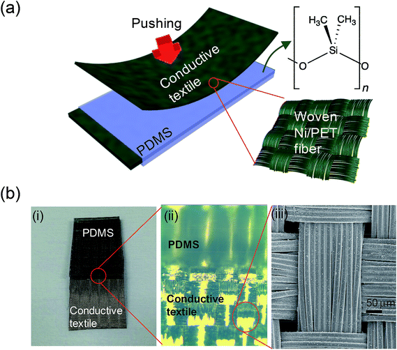 | ||
| Fig. 1 (a) Schematic diagram of the triboelectric generator with the PDMS coated CT (bottom layer) and the bare CT (top layer), (b) photographic and FE-SEM images of the PDMS coated CT. | ||
Fig. 2 shows the (a) photographic image of the fabricated triboelectric generators with the PDMS coated CT and bare CT, and (b) schematic diagram of the operating mechanism under an external pushing force. To facilitate the characterization of output voltage and current density, the top (bare CT) and bottom (PDMS coated CT) electrodes of the triboelectric generators were connected to the external aluminum (Al) foil and CT, respectively (Fig. 2(a)(i)). As shown in Fig. 2(a)(ii), a thin elastic sponge covered the stacked layers of the PDMS coated CT and bare CT as a buffer layer, which protected the stacked layers from the direct pushing force. To prevent dust intrusion from air and touched materials, the sample was packed with polyester wipers, as shown in Fig. 2(a)(iii). Considering the contact electrification of the devices, the operating mechanism can be explained by a theoretical model for conductor-to-dielectric contact-mode triboelectric generators.11 Then, the footsteps test was carried out by monitoring the external pushing force. The operating mechanism of the triboelectric generators is explained in Fig. 2(b). When the sample was compressed by the external pushing force, the top electrode (bare CT) was contacted and rubbed with the PDMS at the friction area. During the rubbing and friction with deformation of the PDMS, the positive and negative triboelectric charges were generated and distributed at the bare CT and the PDMS according to their triboelectric tendency. While the textile surface of the CT was partially separated with an air gap, a dipole moment was formed in the dielectric PDMS. As a result, electric charges were driven by the induced electric potential difference and this process continued until a neutralization occurred between the two electrodes. After the withdrawal of external pushing force, the electric potential was reversed through releasing the deformation of the PDMS. Therefore, the electric charges flowed in the opposite direction.
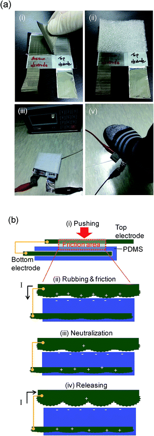 | ||
| Fig. 2 (a) Photographic images of the fabricated triboelectric generators with the PDMS coated CT and bare CT, and (b) schematic diagram of the operating mechanism under an external pushing force. | ||
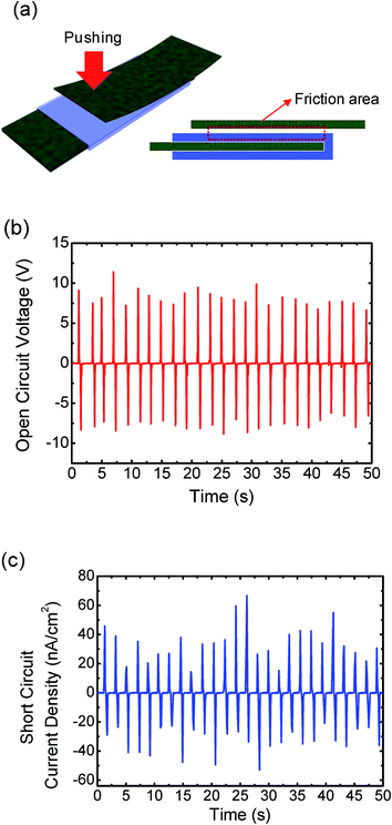
Fig. 3 shows (a) the schematic diagram of the single-layer triboelectric generator formed by overlapping the PDMS coated CT and the bare CT, and the measured output (b) voltage and (c) current density curves of the fabricated single-layer triboelectric generator under the footsteps test. Herein, the external pushing forces of 3.5–4 kgf were applied to the device at a repetition rate of 0.5 Hz, where the pushing frequency was synchronized with a metronome. For all the measured output voltage and current density curves, the positive/negative peaks were alternated with cycled pushing and releasing processes. This switching speed was estimated in terms of an internal time, i.e., the time spent between the positive and next negative peaks. For one cycle of pushing and releasing, a short interval time of 0.42 s was observed for the textile surface of bare PDMS and CT. In comparison with previous work (interval time of 1.84 s with bare PDMS and ITO),23 this result is very encouraging for rapid operation. As shown in Fig. 3(b), the regular output voltage peaks were obtained for 50 s. For the friction area of a single layer in Fig. 3(a), the averaged output voltage of 8.12 V was observed. In contrast, the measured output current density curves exhibited slightly irregular peaks (Fig. 3(c)). In fact, the current density was created across an external load between both electrodes and it was strongly affected by the variation of electric potential as well as the change of capacitance in the device.12 Mechanical deformation of the compressed layer changes the distance between both electrodes, which leads to a resultant variation in the capacitance. In this regard, the change in distance may be different at every moment during the pushing because the single layer of triboelectric PDMS causes a large mechanical deformation under the footsteps test. The averaged output current density was obtained to be 25.76 nA cm−2. In addition, the air gap distance is important to increase the charge transfer according to V–Q–x relationship, where V, Q and x are the potential difference, the amount of charge, and the gap distance between two electrodes, respectively.11 Therefore, to create an efficient separation, several spacers including sponges or springs have been inserted between the two layers.14,23 However, these types of design could not be suited for wearable or flexible triboelectric generators because a large space would be required for packaging the device with such spacers. Moreover, the textile surface of the CT spontaneously created an air gap in the partial area without additional spacers, which are available to be directly layered or stacked. By further optimizing the interstitial layer as a spacer with a fabric mesh or sheet, it can be expected that the performance will be improved by increasing the air gap without having a large space.
Fig. 4 shows (a) the schematic diagram of the double- and triple-stacked triboelectric generators, and the measured output (b) voltage and (c) current density curves of the triboelectric generators. As depicted in Fig. 4(a), the multi-stacked triboelectric generators were fabricated by overlapping the PDMS coated CTs and the bare CTs repeatedly. In the same way, to package the single-layer triboelectric generator (Fig. 2(a)(i)), the top and bottom electrodes were connected together with Al foil. The friction area was marked by a red-dashed rectangle. When the external pushing force is applied into multi-stacked triboelectric generators, negative triboelectric charges are distributed at the upper and bottom surfaces of PDMS in the corresponding friction area. Therefore, the amount of triboelectric charge and the charge transfer can be increased, thus leading to an enhanced output voltage and current density through an operating mechanism, as explained in Fig. 2(a).
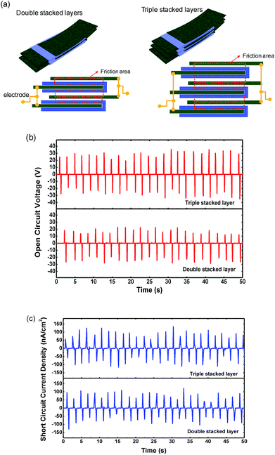 | ||
| Fig. 4 (a) Schematic diagram of the double/triple-stacked triboelectric generators, and measured output (b) voltage and (c) current density curves of the corresponding devices. | ||
For the double- and triple-stacked triboelectric generators, by stacking the layers, the friction area is increased three and five times, respectively, which enhanced the output voltages and current densities. In Fig. 4(b), under the external pushing forces of 3.5–4 kgf at 0.5 Hz, the averaged output voltages were increased to 15.18/23.39 V for double/triple-stacked devices. Compared to the single-layer triboelectric generator (Fig. 3(a)), the averaged output voltages of the corresponding devices were increased up to 1.87/2.88 times. In the same way, the averaged output current densities of the double/triple-stacked devices were also increased up to 44.84 nA cm−2 (1.74 times)/63.13 nA cm−2 (2.45 times), respectively. Furthermore, the output current density peaks were more regular than those of the single-layer device. This can be explained by the fact that the multi-stacked layers reduce the changed distance between both electrodes from the mechanical deformation under the external pushing force. Therefore, the variation in capacitance would be almost the same with every push, and thus produce the improved regular output current density peaks.
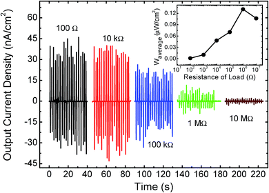
In order to analyze the device performance, the output current densities of the triple-stacked triboelectric generator were measured with different external loads from 100 Ω to 10 MΩ, as shown in Fig. 5. As the resistance of the external load was increased, the output current density peaks gradually decreased from 63.13 to 0.85 nA cm−2 under the external pushing forces of 3.5–4 kgf at 0.5 Hz. The inset of Fig. 5 shows the calculated average power density (Waverage) according to the following equation:
 | (1) |
Conclusions
The multi-stacked triboelectric generators with the PDMS coated CT and bare CT, which can be fabricated by a facile and cost-effective method, were successfully demonstrated. Owing to the textile surface of the CT, the efficient triboelectric charge generation and separation was achieved with the PDMS coated CT. Under a footsteps test with 3.5–4 kgf of external pushing forces, the single-layer of triboelectric generator exhibited the averaged output voltage/current density of 8.12 V/26.57 nA cm−2 with a short interval time of 0.42 s. The multi-stacked triboelectric generators were simply prepared by overlapping the PDMS coated CTs and the bare CTs repeatedly. Because the friction area was increased three and five times for double and triple stacked devices, the averaged output voltages/current densities were increased by 1.87/1.74 and 2.88/2.45 times, respectively. For the triple-stacked triboelectric generator with the external load of 1 MΩ, the maximum Waverage value of 0.125 μW cm−2 was obtained under 3.5–4 kgf of external pushing forces at 0.5 Hz. These results may provide a deep insight into the triboelectric generators for efficient energy harvesting.Acknowledgements
This work was supported by the National Research Foundation of Korea (NRF) grant funded by the Korea government (MSIP) (no. 2013-068407).References
- X. Chen, S. Xu, N. Yao and Y. Shi, Nano Lett., 2010, 10, 2133 CrossRef CAS PubMed.
- R. Yu, W. Wu, Y. Ding and Z. L. Wang, ACS Nano, 2013, 7, 6403 CrossRef CAS PubMed.
- Z. H. Lin, G. Zhu, Y. S. Zhou, Y. Yang, P. Bai, J. Chen and Z. L. Wang, Angew. Chem., Int. Ed., 2013, 52, 1 CrossRef.
- B. Meng, W. Tang, Z. Too, X. Zhang, M. Han, W. Liu and H. Zhang, Energy Environ. Sci., 2013, 6, 3235 Search PubMed.
- M. Lee, C. Y. Chen, S. Wang, S. N. Cha, Y. J. Park, J. M. Kim, L. J. Chou and Z. L. Wang, Adv. Mater., 2012, 24, 1759 CrossRef CAS PubMed.
- X. S. Zhang, M. D. Han, R. X. Wang, F. Y. Zhu, Z. H. Li, W. Wang and H. X. Zhang, Nano Lett., 2013, 13, 1168 CrossRef CAS PubMed.
- Y. Yang, H. Zhang, J. Chen, S. Lee, T. C. Hou and Z. L. Wang, Energy Environ. Sci., 2013, 6, 1744 CAS.
- F. R. Fan, Z. Q. Tian and Z. L. Wang, Nano Energy, 2012, 1, 328 CrossRef CAS PubMed.
- G. Zhu, Z. H. Lin, Q. Jing, P. Bai, C. Pan, Y. Yang, Y. Zhou and Z. L. Wang, Nano Lett., 2013, 13, 847 CrossRef CAS PubMed.
- S. M. Niu, Y. Liu, S. H. Wang, L. Lin, Y. S. Zhou, Y. F. Hu and Z. L. Wang, Adv. Mater., 2013, 25, 6184 CrossRef CAS PubMed.
- S. Niu, S. Wang, L. Lin, Y. Liu, Y. S. Zhou, Y. Hua and Z. L. Wang, Energy Environ. Sci., 2013, 6, 3576 Search PubMed.
- F. R. Fan, L. Lin, G. Zhu, W. Wu, R. Zhang and Z. L. Wang, Nano Lett., 2012, 12, 3109 CrossRef CAS PubMed.
- Y. Yang, L. Lin, Y. Zhang, Q. Jing, T. C. Hou and Z. L. Wang, ACS Nano, 2012, 6, 10378 CrossRef CAS PubMed.
- T. C. Hou, Y. Yang, H. Zhang, J. Chen, L. J. Chen and Z. L. Wang, Nano Energy, 2013, 2, 856 CrossRef CAS PubMed.
- L. Lin, S. Wang, Y. Xie, Q. Jing, S. Niu, Y. Hu and Z. L. Wang, Nano Lett., 2013, 13, 2916 CrossRef CAS PubMed.
- G. Yu, L. Hu, M. Vosgueritchian, H. Wang, X. Xie, J. R. McDonough, X. Cui, Y. Cui and Z. Bao, Nano Lett., 2011, 11, 2905 CrossRef CAS PubMed.
- R. H. Guo, S. X. Jiang, Y. D. Zheng and J. W. Lan, Appl. Polym. Sci., 2013, 127, 4186 CrossRef CAS.
- E. Dahan and P. R. Sundararajan, Soft Matter, 2014, 10, 5337 RSC.
- K. Yu and Y. Han, Soft Matter, 2006, 2, 705 RSC.
- F. Gaudière, I. Masson, S. Morin-Grognet, O. Thoumire, J. P. Vannier, H. Atmani, G. Ladam and B. Labat, Soft Matter, 2012, 8, 8327 RSC.
- J. Yu, S. Chary, S. Das, J. Tamelier, K. L. Turner and J. N. Israelachvili, Langmuir, 2012, 28, 11527 CrossRef CAS PubMed.
- Y. H. Ko, G. Nagaraju, S. H. Lee and J. S. Yu, ACS Appl. Mater. Interfaces, 2014, 6, 6631 CAS.
- J. Chen, G. Zhu, W. Yang, Q. Jing, P. Bai, Y. Yang, T. C. Hou and Z. L. Wang, Adv. Mater., 2013, 6094 CrossRef CAS PubMed.
| This journal is © The Royal Society of Chemistry 2015 |

