
 Open Access Article
 This Open Access Article is licensed under a
 Creative Commons Attribution 3.0 Unported Licence
Nano-ZnO impregnated inorganic–polymer hybrid thinfilm nanocomposite nanofiltration membranes: an investigation of variation in structure, morphology and transport properties
Avishek
Pal
a,
T. K.
Dey
*a,
Anshu
Singhal
b,
R. C.
Bindal
a and
P. K.
Tewari
a
aDesalination Division, Bhabha Atomic Research Centre, Trombay, Mumbai, India 400085. E-mail: tkdey@barc.gov.in; tkdey2002@yahoo.com
bChemistry Division, Bhabha Atomic Research Centre, Trombay, Mumbai, India 400085
First published on 13th April 2015
Abstract
Inorganic–polymer hybrid, thinfilm nanocomposite nanofiltration (TFN-NF) membranes prepared by in situ interfacial polymerization of branched polyethyleneimine and trimesoyl chloride, with simultaneous impregnation of as-synthesized hexagonal wurtzite ZnO nanocrystals (nano-ZnO), either through aqueous or organic phase, have been extensively characterized. XPS analysis revealed that there was no inter-atomic charge transfer between nano-ZnO and host polyamide matrix, indicating that no formation of chemical bonding occurred between them in the skin layers of the membranes. The type of interaction present within the nanocomposite polyamide matrices of the membranes was through formation of noncovalent type secondary chemical interactions with peripheral hydroxyl groups of nano-ZnO and polyamide network as substantiated through FTIR analysis. SEM revealed the formation of distinct patterns and coils, through multiple-point interactions between the nano-ZnO and the polyamide network in the membranes' skin surfaces when introduced through aqueous amine phase. However, when introduced through the organic phase, nanomaterials remained distributed as discrete clusters within the membranes' skin layers because of lack of polar environment around the reaction zone, further emphasizing the role of the medium in which the nanomaterials are incorporated. AFM showed variation of surface roughness features with change in the precursor medium of introduced nano-ZnO. Nanofiltration performance towards different solutes, providing differential rejections in the order of MgCl2 > NaCl ≥ Na2SO4, revealed that the membranes were distinctly positively charged. Solvent fluxes of the membranes were significantly higher when nanomaterials were introduced through the aqueous phase as compared to the organic phase.
1. Introduction
Pressure-driven nanofiltration (NF) membrane processes have become significantly useful in recent years in aqueous stream separations. They offer exciting options for various industrial applications due to their ability to achieve high selectivity between mono and multivalent ionic species from mixed electrolyte streams, with additional advantages such as low transmembrane pressure, low operational cost and high permeate flux.1,2 Thin film composite (TFC) type membranes having an ultrathin selective barrier layer, generally produced by in situ interfacial polycondensation of reactive monomers on a suitable substrate material, constitute the majority of commercially available polymeric nanofiltration membranes. The barrier skin layer, made of synthetic polymeric materials, additionally and preferentially containing either negative or positive charge-bearing functionalities, influences the separation behaviors of the membrane by preferentially retaining certain components and allowing the passage of certain others, depending on interaction between surface charge of the membrane and charges of the solutes under consideration.3,4 The major areas of application for these membranes include bulk wet-stream processing such as water purification for production of drinking water, effluent treatment for removal of toxic elements,5 dairy industries,6 food and pharmaceutical industries,7,8 textile industries,9 and biotechnological industries.10For almost a decade, when it seemed that membrane performance in terms of solute rejection, and especially the solvent flux, had reached its limits, the advent of nanotechnology provided a new dimension to scientists by changing the scenario.11 Membranologists explored promising ways to overcome some of the limitations associated with synthetic polymeric membranes by developing new types of organic–inorganic hybrid nanocomposite materials.12–14 Extensive research on various metals and metal oxides as well as ceramic and zeolite nanoparticles has been conducted to obtain improved physicochemical properties in the membranes. Production of membranes by incorporating nanomaterials resulted in better chemical, mechanical and thermal resistance and also prevented adhesion as well as adsorption of the undesired fouling materials on their surfaces, thereby maintaining membrane permeability and selectivity as well as minimizing the load on pretreatment and chemical cleaning. It has been observed that microstructural features of the membranes are affected by site-specific interaction between the metal oxide nanoparticle and the host polymer matrix, altering the skin layer morphology, pore size, pore size distribution, surface roughness, and so on, which eventually influence their performances. Various metal oxide nanoparticles such as silica (SiO2),15,16 alumina (Al2O3),17,18 titania (TiO2),19–21 ferric oxide (Fe2O3),22 zinc oxide (ZnO),23,24 and zeolites,25,26 have been employed as nanofillers in nanocomposite membranes' polymeric host matrix leading to promising improvements like better chemical and thermomechanical properties.
ZnO nanoparticles have recently attracted membranologists' attention as a suitable nontoxic, bio-safe and bio-compatible material with strong inhibitory and antibacterial effects over a broad spectrum of both G+ and G− bacteria.27–29 Adams et al.,30 Brayner et al.31 and Jeng and Swanson32 have reported that ZnO is more efficient in controlling the growth of micro-organisms than other metal oxides such as SiO2, MgO, TiO2 and CaO, by significantly inhibiting the growth of a wide range of pathogenic bacteria under visible light conditions. The commonly proposed antimicrobial mechanisms for nano-ZnO are (1) generation of reactive oxygen species like hydrogen peroxide (H2O2), hydroxyl radical (˙OH) and singlet oxygen (1O2) from the surface of zinc oxide, penetrating the cell membrane and inhibiting cell growth, and (2) rupture of the cell membrane and leakage of cytoplasmic content because of binding between the bacterial cell and ZnO nanoparticles due to electrostatic forces.33–35
The present study emphasizes investigations of structural and physicochemical features of inorganic–polymer hybrid, thinfilm nanocomposite nanofiltration (TFN-NF) membranes, prepared by impregnation of as-synthesized nano-ZnO into the polymer skin layer during the in situ interfacial polycondensation of branched polyethyleneimine (PEI) and trimesoyl chloride (TMC). The synthesized nano-ZnO has been characterized by X-ray powder diffraction (XRD) analysis, Fourier transform infra-red (FTIR) spectroscopy, Raman spectroscopy and X-ray photoelectron spectroscopy (XPS). For membranes, XPS as well as FTIR analysis of skin layers showed the influence of nano-ZnO, with variation in the ways of incorporation, on the electronic- and molecular-level interactions occurring within the nanocomposite polyamide matrices of the TFN-NF membranes. Changes in surface morphologies of the skin layer of nanocomposite membranes were investigated via scanning electron microscopy (SEM). Quantitative surface roughness analysis via atomic force microscopy (AFM) was applied to probe the role of nanomaterials in influencing membrane topographies. Energy dispersive X-ray (EDX) analysis has been employed to determine the elemental composition of TFN-NF membrane skin layers. Cross-flow permeation experiments were performed to correlate the variation in physicochemical features of the membranes with their transport parameters such as solute rejection and solvent flux behaviors.
2. Experimental section
2.1 Materials
For preparation of the polysulfone (Psf) base membrane, polysulfone (Psf; MW: 30![[thin space (1/6-em)]](https://www.rsc.org/images/entities/char_2009.gif) 000 Da) procured from Solvay Speciality Polymers (India); N-methyl-2-pyrrolidone (NMP) with a relative vapor density of 3.4 (versus air) and purity of ≥99%, from Sigma-Aldrich; and polyvinyl pyrrolidone (PVP, K-30; MW: 40000 Da) procured from SRL (India) were employed. The nonwoven porous polyester fabric used as a support material for making the base membrane had a density of 75 g m−2 and a thickness of 110 μm with air permeability of 70 dm3 m−2 at 2 mbar. Aqueous solution (50 w/v%) of branched poly(ethyleneimine) (PEI; MW: 600000–1000000 Da; d204: 1.08), typically constituting about 25% primary, 50% secondary and 25% tertiary amine groups and trimesoyl chloride (TMC) with 98% purity, procured from Sigma-Aldrich, was used without further purification. The organic solvent, extrapure (99%) AR-grade n-hexane was procured from SRL (India). Various AR-grade electrolytes, including magnesium chloride heptahydrate (MgCl2·7H2O), anhydrous sodium sulphate (Na2SO4) and sodium chloride (NaCl), were obtained from different companies in India. The conductivity of ultra-pure water used for preparation of monomer solutions, and membrane preparation as well as nanofiltration experiments was below 2 μS cm−1. Zinc(II) acetylacetonate hydrate (99.995% purity) [Zn(acac)2·H2O] was obtained from Sigma-Aldrich.
000 Da) procured from Solvay Speciality Polymers (India); N-methyl-2-pyrrolidone (NMP) with a relative vapor density of 3.4 (versus air) and purity of ≥99%, from Sigma-Aldrich; and polyvinyl pyrrolidone (PVP, K-30; MW: 40000 Da) procured from SRL (India) were employed. The nonwoven porous polyester fabric used as a support material for making the base membrane had a density of 75 g m−2 and a thickness of 110 μm with air permeability of 70 dm3 m−2 at 2 mbar. Aqueous solution (50 w/v%) of branched poly(ethyleneimine) (PEI; MW: 600000–1000000 Da; d204: 1.08), typically constituting about 25% primary, 50% secondary and 25% tertiary amine groups and trimesoyl chloride (TMC) with 98% purity, procured from Sigma-Aldrich, was used without further purification. The organic solvent, extrapure (99%) AR-grade n-hexane was procured from SRL (India). Various AR-grade electrolytes, including magnesium chloride heptahydrate (MgCl2·7H2O), anhydrous sodium sulphate (Na2SO4) and sodium chloride (NaCl), were obtained from different companies in India. The conductivity of ultra-pure water used for preparation of monomer solutions, and membrane preparation as well as nanofiltration experiments was below 2 μS cm−1. Zinc(II) acetylacetonate hydrate (99.995% purity) [Zn(acac)2·H2O] was obtained from Sigma-Aldrich.
2.2 Synthesis of ZnO nanocrystals
ZnO nanocrystals (nano-ZnO) were synthesized by thermal decomposition of anhydrous Zn(acetylacetonate)2 in n-octylamine at temperature as low as 110 °C. The precursor anhydrous Zn(acetylacetonate)2 was prepared following the Rudolph and Henry method.36 In a typical preparation, 0.5 g (1.89 mmol) of anhydrous Zn(acetylacetonate)2 was combined in a 50 mL three-neck flask with 10 mL (∼60.5 mmol) of n-octylamine. The reaction flask was evacuated to a vacuum level of 2 mbar for 30 min at 40 °C. The reaction system was then heated (∼10 °C min−1) to 110 °C under argon flow and maintained at this temperature for 2 h. The obtained white suspension was cooled to 60 °C and 5 mL of methanol was added to the reaction flask. The nanocrystals of ZnO were recovered by centrifugation, dispersed in toluene, and precipitated by adding methanol. The redispersion and precipitation steps were repeated twice to remove any unreacted precursors and excess solvent.2.3 Preparation of Psf base membrane
The flat-sheet microporous Psf base membrane was prepared following the nonsolvent induced phase inversion method, where a homogeneous casting solution, comprised of 30 (w/v)% Psf in NMP, along with the pore-forming additive, PVP (40 w/w% of Psf), was cast on a nonwoven polyester substrate to a thickness of 100 μm using an automated casting machine. The membrane was immediately dipped in a water bath and maintained at room temperature for immersion precipitation. The water of the bath was changed several times to ensure complete removal of the solvent (NMP) and additive (PVP) from the membrane matrix via leaching. The entire casting machine was kept in an environmentally controlled atmosphere where temperature and relative humidity were maintained at 25 °C and 35–40%, respectively. This Psf membrane was subsequently used as a base material for preparation of the thinfilm nanocomposite nanofiltration (TFN-NF) membranes.2.4 Preparation of Control-NF and inorganic–polymer hybrid TFN-NF membranes
A control, thinfilm composite nanofiltration membrane (Control-NF), devoid of any nanomaterial, was prepared by in situ interfacial polycondensation reaction (Scheme 1) between PEI (in aqueous medium) and TMC (in organic, n-hexane medium). A piece of microporous Psf base membrane was treated with 4 (w/v)% aqueous solution of PEI for 4 min. After removing the amine soaked base membrane from the aqueous medium and eliminating the excess solution by gently squeezing it between two rubber rollers, the membrane was dipped in a 0.1 (w/v)% TMC solution for 30 s. The nascent TFC membrane, comprised of a freshly deposited, ultrathin polyamide film over the surface of the Psf base membrane, was further heat cured at 90 °C in a hot-air circulated oven for 30 min.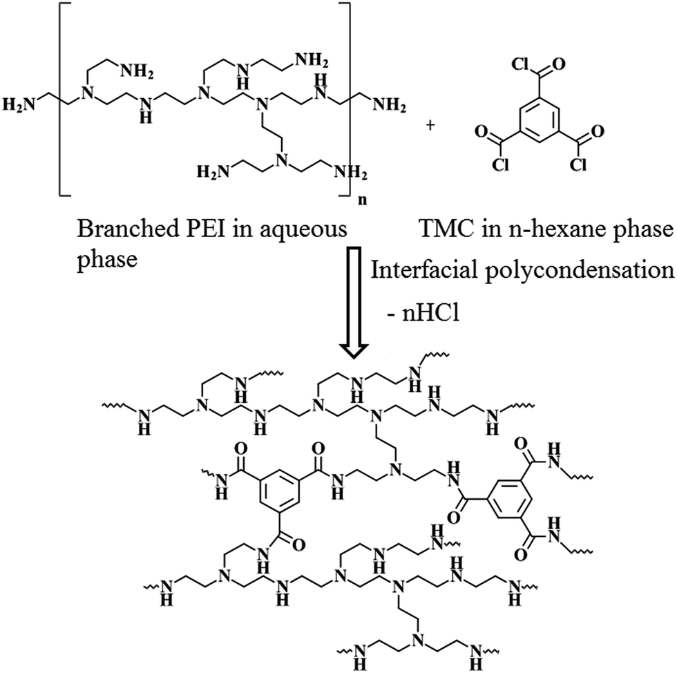 | ||
| Scheme 1 Synthesis of polyamide layer of Control-NF from PEI and TMC following in situ interfacial polycondensation process. | ||
For development of the inorganic–polymer hybrid TFN-NF membranes, the nano-ZnO was introduced in either aqueous or organic phase. The nano-ZnO was dispersed in aqueous or n-hexane medium by applying ultrasonication for 15 min prior to the start of the membrane-making process. When prepared by incorporation of the nano-ZnO through the aqueous phase, 4 (w/v)% aqueous solutions of PEI containing well-dispersed nano-ZnO of varying concentrations: 0.05, 0.1 and 0.2 (w/v)% were used. The membranes were prepared using the same procedure as for the Control-NF by performing an in situ interfacial polycondensation reaction with 0.1 (w/v)% TMC solution (schematics in Fig. 1a), followed by curing at 90 °C for 30 min. These membranes were named Aq-ZnO:TFN-NF-1, Aq-ZnO:TFN-NF-2 and Aq-ZnO:TFN-NF-3, respectively.
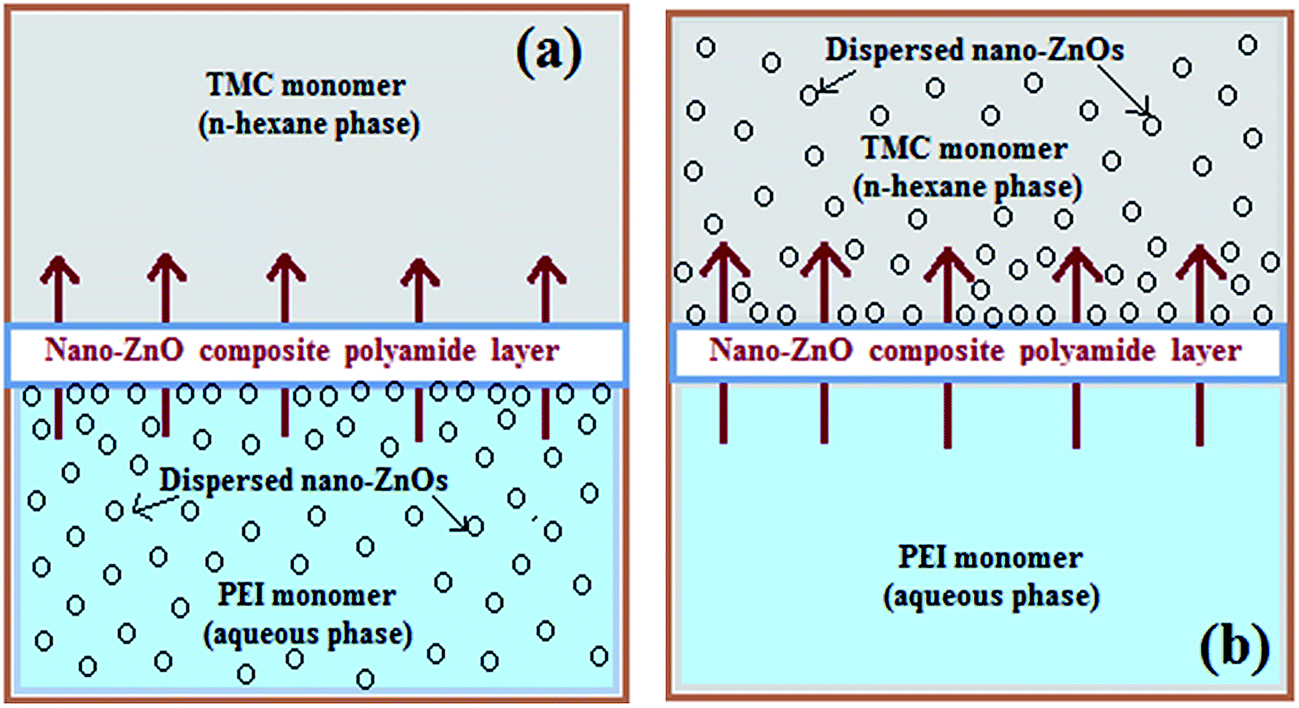 | ||
| Fig. 1 Schematics of two different pathways: (a) through aqueous phase of PEI and (b) through n-hexane phase of TMC, for nano-ZnO incorporation in thin skin layer of TFN-NF membranes by in situ interfacial polycondensation process. The arrows indicate direction of diffusion of PEI monomer across interfacially formed polymeric barrier layer to react with TMC at organic phase side. | ||
Similarly, in another set of experiments, nano-ZnO of various concentrations of 0.05, 0.1 and 0.2 (w/v)% were ultrasonically dispersed in n-hexane, containing 0.1 (w/v)% TMC monomer. The in situ interfacial polycondensation was conducted adopting the same approach as for the Control-NF, with 4 (w/v)% aqueous PEI solution (schematics in Fig. 1b), followed by curing at 90 °C for 30 min. These membranes were named Org-ZnO:TFN-NF-1, Org-ZnO:TFN-NF-2 and Org-ZnO:TFN-NF-3, respectively. They were washed with de-ionized water to remove the leachable chemicals before conducting performance evaluation tests.
2.5 Textural and structural characterizations of as-synthesized nano-ZnO
Phase purity and structure of the ZnO nanocrystals were determined by X-ray powder diffraction (XRD) data, which were collected on a Philips X'Pert pro X-ray diffractometer using Cu-Kα radiation (λ = 1.5418 Å) at 40 kV and 30 mA.The FTIR spectrum of the ZnO nanocrystals was recorded in attenuated total reflectance (ATR) mode using a Bruker Vertex 70 FTIR spectrometer, in the range of 500–1500 cm−1.
Micro-Raman spectra of the nanocrystals were obtained on a LABRAM-I, ISA-make spectrometer using an Ar+ ion laser (488 nm) equipped with a Peltier-cooled CCD detector.
For XPS characterization of the ZnO nanocrystals, a DESA-150 electron analyzer (Staib Instruments, Germany) equipped with a Mg-Kα X-ray source (1253.6 eV) was employed. The spectrometer's binding energy scale was calibrated with the Au-4f7/2 photopeak at a binding energy (BE) of 83.95 eV. Curve fittings of intensity versus binding energy (BE) plots comprising the multiplex photo peaks were performed employing a least-squares peak analysis software (XPSPEAK 4.1). Using the Gaussian/Lorentzian sum function, peak areas as well as corresponding full width at half-maximum (FWHM) were also determined for the high-resolution Zn-2p and O-1s spectra. The fitting error in both peak position and FWHM are ∼0.1 eV.
2.6 Characterization of TFN-NF membranes
Steady-state solute rejections of the membranes were determined by measuring the solute concentrations in the feed and permeate using a digital conductivity meter (TESTRONIX 15, Microlab, Mumbai, India). The percent solute rejection, R, was calculated using the following expression:
| R = (1 − Cp/Cf) × 100 | (1) |
The corresponding permeate solvent flux (JW) was determined by direct measurement of the permeate flow, V (mL), through the membrane of area A (cm2), for a given time t (min), using expression (2), and presented in liters per meter2 per day (LMD).
| JW = V/At | (2) |
3. Results and discussion
3.1 Analysis of textural and structural features of nano-ZnO
The X-ray diffraction patterns of nano-ZnO obtained by thermal decomposition of the acetylacetonate in n-octylamine at 110 °C are shown in Fig. 2. The patterns can be indexed to hexagonal wurtzite lattice structure of the nano-ZnO. The indexing to X-ray patterns is attributed to (100), (002), (101), (102), (110), (103), (200), (112), (201), (004) and (202) peaks of the hexagonal crystalline phase for nano-ZnO. The average crystallite sizes as determined using Scherrer's formula (t = Kλ/Bcosθ, where t = average crystallite size in Å, K = Scherrer constant usually taken as 0.9 Å, λ = X-ray wavelength, θ is the Bragg angle, and B = integral breadth of a reflection located at 2θ) are ranged from 22 ± 2 nm. The lattice structure of the nanocrystals of ZnO can be depicted as a number of alternating planes arranged in tetrahedral and/or octahedral fashion through coordination of O2− and Zn2+ ions, stacked alternately along the c-axis.
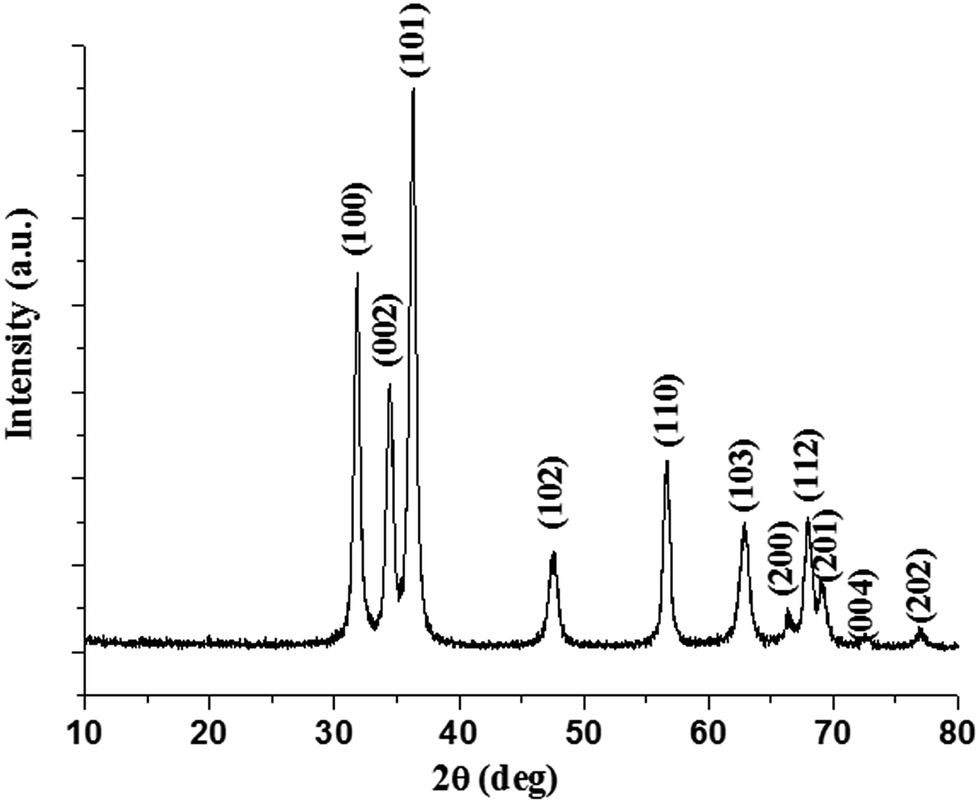 | ||
| Fig. 2 XRD pattern of as-synthesized nano-ZnO. | ||
The FTIR spectrum of the as-synthesized ZnO nanocrystals, acquired in atmospheric conditions, is shown in Fig. 3. The most prominent band at 510 cm−1 and a weak band at 660 cm−1 are assigned to the stretching vibrations of Zn–O bonds in the tetrahedral and octahedral coordinations, respectively.38
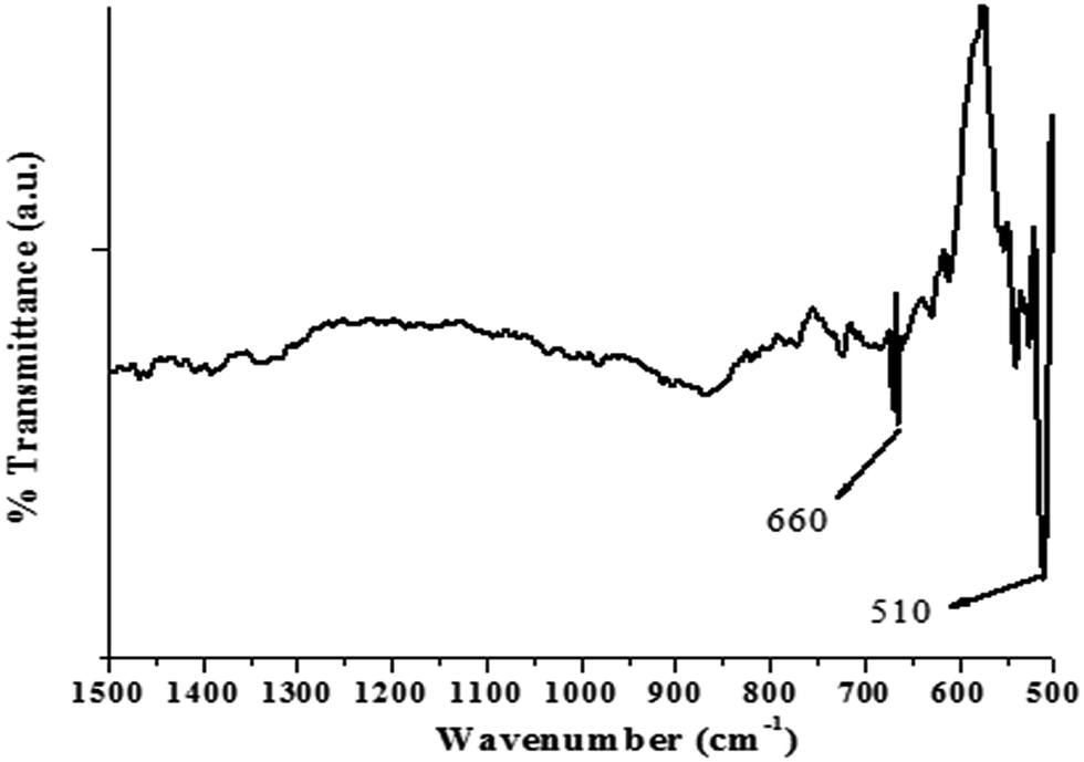 | ||
| Fig. 3 FTIR spectra for nano-ZnO. | ||
A Raman spectrum of the ZnO nanocrystals acquired at room temperature is shown in Fig. 4. The hexagonal wurtzite structure of ZnO belongs to the space group C46v with two formulae units per primitive cell, where all atoms occupy C3v sites. The Raman active zone-centre optical phonons predicted by group theory are A1 + 2E2 + E1. Of these, the phonons of A1 and E1 symmetry are polar and both Raman and IR active. Hence, they show different frequencies for the transverse optical (TO) and longitudinal optical (LO) phonons. A weak band at 407 cm−1 is assigned to E1TO phonon mode. The nonpolar optical phonon modes with symmetry E2, being Raman active only, exhibit dual frequencies where E2 (low frequency) at 99 cm−1 is associated with oxygen atoms, and E2 (high frequency) at 437 cm−1 is associated with the Zn sublattice, which are characteristic of the wurtzite hexagonal phase of ZnO.39–42 The XRD, FTIR and Raman scattering measurements confirm the formation of ZnO nanocrystals in hexagonal wurtzite structure.
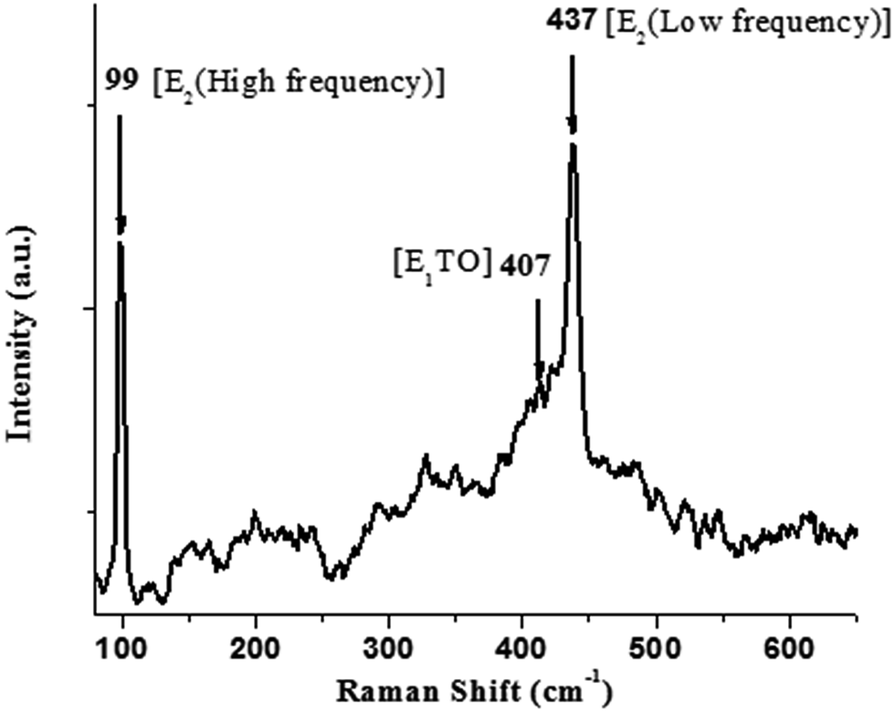 | ||
| Fig. 4 Room-temperature Raman spectrum for nano-ZnO. | ||
XPS analysis of the ZnO nanocrystals exhibits the presence of a strong peak (Fig. 5a) at 1020.5 eV with FWHM of 2.20 eV, attributed to Zn-2p3/2 and a weaker peak at 1043.8 eV with FWHM of 2.21 eV attributed to Zn-2p1/2.43 In Fig. 5b, the component peaks of the deconvoluted O-1s photoelectron spectrum show the presence of a dominant O-1s peak with the lowest BE centered at 529.8 eV with FWHM of 1.79 eV, which can be indexed to the surface and near-surface region lattice oxygen of the nano-ZnO hexagonal lattices. A distinct higher BE of O-1s peak at 531.3 eV, with FWHM of 1.63 eV, can be ascribed to the strongly anchored hydroxyl groups (Zn–OH) at different intrinsic or extrinsic defect sites or oxygen vacancies (Ov) of nano-ZnO.44 However, the weakest but relatively broadened shoulder peak at 532.5 eV with FWHM of 2.04 eV is due to chemisorbed oxygen contributed by surface hydroxyl groups.45
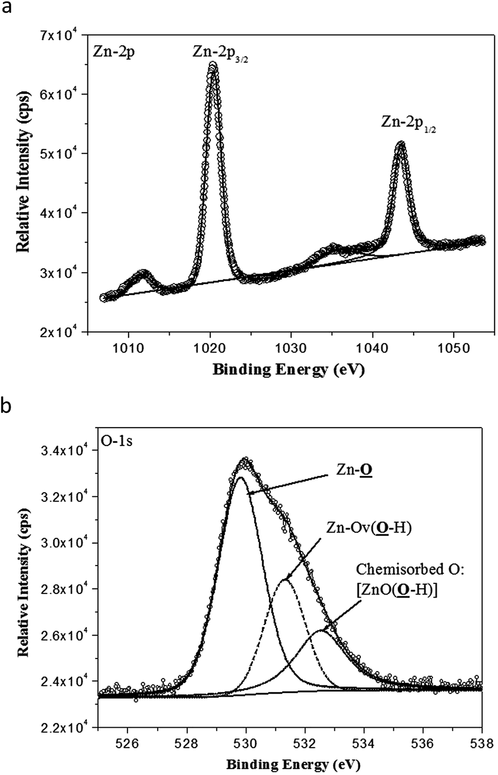 | ||
| Fig. 5 (a) High-resolution Zn-2p3/2 and Zn-2p1/2 photoelectron spectra obtained from nano-ZnO. Line with bullets = experimental data; solid line = curve fit of experimental data; Zn-2p3/2 = 1020.5 eV peak contribution; and Zn-2p1/2 = 1043.8 eV peak contribution. (b) High-resolution O-1s photoelectron spectra obtained from nano-ZnO. Line with bullets = experimental data; solid line = curve fit of experimental data; Zn–O = 529.8 eV peak contribution; Zn–Ov(O–H) = 531.3 eV peak contribution; and ZnO(O–H): 532.5 eV peak contribution. | ||
3.2 Characterization of skin layers of TFN-NF membranes by XPS
Representative TFN-NF membranes, one each from the series made by introducing nano-ZnO through aqueous phase as well as organic phase (i.e., Aq-ZnO:TFN-NF-2 and Org-ZnO:TFN-NF-2), were employed for XPS analysis to investigate the electronic- and molecular-level interactions of the nanocomposite polyamide skin layers within the XPS probe depth (5–10 nm). Further, comparisons of XPS analysis of skin layers of these two membranes with that of the Control-NF were made, with respect to the variation in core-level binding energies and respective peak areas, to study the effect of nano-ZnO impregnation in polyamide matrices.The Zn-2p photoelectron spectra of nano-ZnO impregnated polyamide skin layer of Aq-ZnO:TFN-NF-2 and Org-ZnO:TFN-NF-2 are presented in Fig. 6b and c, respectively. In the case of Aq-ZnO:TFN-NF-2, the high-intensity peak at the low BE of 1020.7 eV (FWHM: 1.87 eV) corresponds to Zn-2p3/2 and the peak at the higher BE with the lower intensity, attributed to Zn-2p1/2, appears at 1044 eV (FWHM: 3.64 eV) (see Table 1). Similarly, for the Zn-2p photoelectron spectrum of Org-ZnO:TFN-NF-2, the peak corresponding to Zn-2p3/2 appears at 1020.6 eV (FWHM: 2.75 eV) and a weaker peak, corresponding to Zn-2p1/2, appears at 1043.7 eV (FWHM: 3.94 eV). The value of the fitting parameter, χ2 resides in the range of 1.12–2.25, which validates the fact of proper fitting of the curves in the Zn-2p XPS spectra. No significant deviations in BE values for Zn-2p3/2, as well as Zn-2p1/2 of both Aq-ZnO:TFN-NF-2 and Org-ZnO:TFN-NF-2, from the corresponding BE values of the pure nano-ZnO, indicate that there is no redistribution of charge density in the Zn–O framework; hence, there is no occurrence of inter-atomic charge transfer between the nano-ZnO and the host polymeric material. In other words, ZnO does not form any chemical bonds with the host polymer matrix during the nanocomposite polymer formation. Thus, it is assumed that only the peripheral hydroxyl groups of nano-ZnO play a role in forming noncovalent type secondary chemical interactions with the polyamide network. However, a decrease in BE accompanied by broadening of peaks for Zn-2p3/2 by 0.88 eV and Zn-2p1/2 by 0.30 eV, from Aq-ZnO:TFN-NF-2 to Org-ZnO:TFN-NF-2, are attributed to the presence of clusters of nano-ZnO with a broad size distribution in the skin surface of the latter membrane, as compared to the former, where the size distribution is much more uniform.46–48
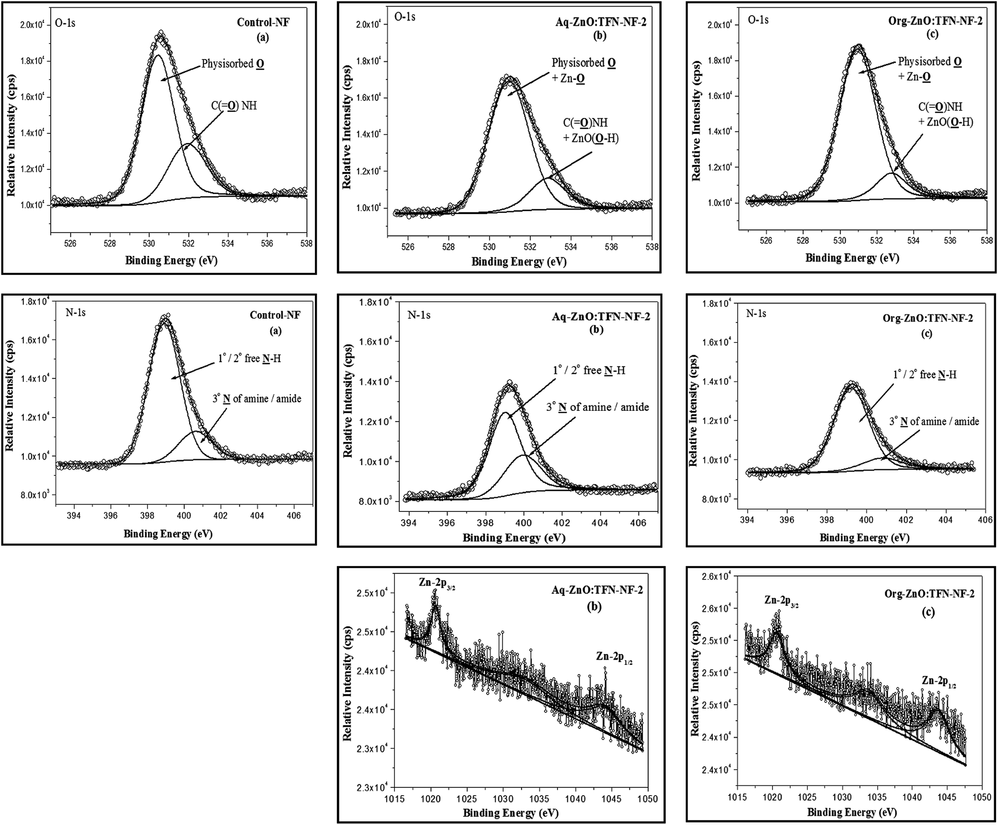 | ||
| Fig. 6 High-resolution O-1s (χ2: 1.00–1.45), N-1s (χ2: 0.90–1.75) and Zn-2p (χ2: 1.12–2.25) photoelectron spectra obtained from nano-ZnO impregnated (a) Control-NF, (b) Aq-ZnO:TFN-NF-2, and (c) Org-ZnO:TFN-NF-2. | ||
| Membrane code | Zn-2p3/2 and Zn-2p1/2 | O-1s | N-1s | ||||||
|---|---|---|---|---|---|---|---|---|---|
| BE (eV) | FWHM (eV) | Peak area (%) | BE (eV) | FWHM (eV) | Peak area (%) | BE (eV) | FWHM (eV) | Peak area (%) | |
| Control-NF | — | 530.4 | 1.99 | 71.18 | 398.9 | 2.04 | 82.26 | ||
| 531.9 | 2.28 | 28.82 | 400.6 | 2.15 | 17.74 | ||||
| Aq-ZnO:TFN-NF-2 | 1020.7 | 1.87 | 42.29 | 530.9 | 2.37 | 80.88 | 399.0 | 2.01 | 68.24 |
| 1044.0 | 3.64 | 57.71 | 532.8 | 2.09 | 19.12 | 400.0 | 2.31 | 31.76 | |
| Org-ZnO:TFN-NF-2 | 1020.6 | 2.75 | 40.88 | 530.9 | 2.36 | 86.02 | 399.2 | 2.09 | 84.82 |
| 1043.7 | 3.94 | 59.12 | 532.7 | 1.99 | 13.98 | 400.7 | 2.40 | 15.18 | |
Fig. 6a–c show the O-1s core-level photoelectron spectra of skin layer polymers for Control-NF, Aq-ZnO:TFN-NF-2, and Org-ZnO:TFN-NF-2, respectively. The curve fitting and deconvolution of each O-1s XPS spectrum yield two constituent spectra, which indicate the presence of oxygen in two different chemical states. The value of χ2 stays in a 1.00–1.45 range, which confirms the fact of proper fitting of the O-1s curves in all spectra. The intense peak with low BE value of 530.4 eV (FWHM: 1.99 eV) for the Control-NF is assigned to physisorbed oxygen (Table 1). The shifting of values to the higher BE of 530.9 eV, with concurrent broadening of peaks for both Aq-ZnO:TFN-NF-2 (FWHM: 2.37 eV) and Org-ZnO:TFN-NF-2 (FWHM: 2.36 eV), refer to the collective contribution of physisorbed oxygen as well as the surface and near-surface region lattice oxygen of the impregnated nano-ZnO. The less intense component shoulder peak of the deconvoluted O-1s spectra with higher BE value of 531.9 eV for Control-NF is assigned to oxygen in the structure of C![[double bond, length as m-dash]](https://www.rsc.org/images/entities/char_e001.gif) O in amide linkages of the polyamide network,49 and those of Aq-ZnO:TFN-NF-2 (BE: 532.8 eV) and Org-ZnO:TFN-NF-2 (BE: 532.7 eV) are contributions from oxygen in the structure of CO in amide linkages of the polyamide network and surface hydroxyl groups of nano-ZnO. The chemical shifts of 0.9 and 0.8 eV for Aq-ZnO:TFN-NF-2 and Org-ZnO:TFN-NF-2, respectively, as compared to Control-NF are ascribed to the chemisorbed surface hydroxyl groups of nano-ZnO. The presence of nano-ZnO leads to an increase in the areas of the major peaks by 9.7 and 14.84% for the Aq-ZnO:TFN-NF-2 and Org-ZnO:TFN-NF-2, respectively over the Control-NF. The relative area is subsequently compensated in the shoulder peak, which is contributed by amide oxygen and chemisorbed surface hydroxyl groups of the impregnated nano-ZnO.
O in amide linkages of the polyamide network,49 and those of Aq-ZnO:TFN-NF-2 (BE: 532.8 eV) and Org-ZnO:TFN-NF-2 (BE: 532.7 eV) are contributions from oxygen in the structure of CO in amide linkages of the polyamide network and surface hydroxyl groups of nano-ZnO. The chemical shifts of 0.9 and 0.8 eV for Aq-ZnO:TFN-NF-2 and Org-ZnO:TFN-NF-2, respectively, as compared to Control-NF are ascribed to the chemisorbed surface hydroxyl groups of nano-ZnO. The presence of nano-ZnO leads to an increase in the areas of the major peaks by 9.7 and 14.84% for the Aq-ZnO:TFN-NF-2 and Org-ZnO:TFN-NF-2, respectively over the Control-NF. The relative area is subsequently compensated in the shoulder peak, which is contributed by amide oxygen and chemisorbed surface hydroxyl groups of the impregnated nano-ZnO.
The component peaks of the N-1s spectra (Fig. 6a–c) with high intensity, at lower BE of 398.9, 399.0 and 399.2 eV, for Control-NF, Aq-ZnO:TFN-NF-2 and Org-ZnO:TFN-NF-2, respectively (Table 1), correspond to the 2° nitrogen atoms of free N–H of polyamides and free 1° as well as 2° amines of the polymer backbone. For N-1s XPS spectra, the χ2 value resides in the 0.90–1.75 range, indicating a proper fit. The peaks with lower intensity at higher BE of 400.6 eV for Control-NF, 400.0 eV for Aq-ZnO:TFN-NF-2, and 400.7 eV for Org-ZnO:TFN-NF-2 are resulted from 3° nitrogen atoms of amides and amines of the polymer backbone as well as nitrogen atoms of amines and amides that are involved in intermolecular H-bondings, either through inter-chain interaction or through the surface hydroxyl groups of nano-ZnO. The peak positions are concordant with reported data in the literature.50 The chemical shifts of the N-1s signals to higher BE values in the case of Control-NF as well as Org-ZnO:TFN-NF-2, as compared to Aq-ZnO:TFN-NF-2, are attributed to enhanced protonation of amine sites during the course of polycondensation reaction of the former two membranes. This may have resulted in an increase in the positive charge densities on N sites of these membranes. The peak area referred to free N–H sites in the polyamide corresponding to the Control-NF, gets decreased by 14.02% as nano-ZnO of 0.1% is incorporated in the skin surface of Aq-ZnO:TFN-NF-2. This is ascribed to the extensive association of the nano-ZnO with N–H of polyamides and 1° as well as 2° amines of polymer backbone, reducing the number of free amine sites. However, the peak area assigned to similar N–H sites corresponding to the Org-ZnO:TFN-NF-2 is increased only by 2.56% as compared to the Control-NF, indicating that there are less extensive H bondings and more free N–H sites. These changes in the areas of the major peaks for Aq-ZnO:TFN-NF-2 and Org-ZnO:TFN-NF-2 are compensated in the areas of the shoulder peaks at a higher BE. The peak areas of N and O are sensitive to the presence and variation of nano-ZnO in the polyamide skin layer, and hence may not be considered as absolute.
3.3 Spectral characterization of TFN-NF membranes by ATR FTIR
ATR FTIR spectrum of Control-NF and those of the TFN-NF membranes, made by introducing nano-ZnO either through the aqueous or organic phase, are presented in Fig. 7a and b, respectively. They show that introduction of progressively increasing amounts of nano-ZnO through either medium leads to significant physicochemical changes in the skin layer polymers of the resulting nanocomposite membranes.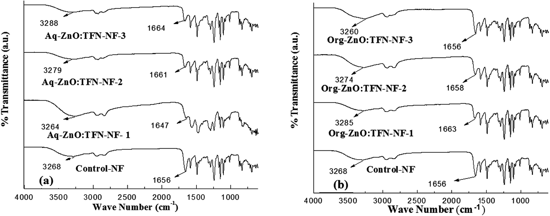 | ||
| Fig. 7 ATR FT IR spectra of skin layers of TFN-NF membranes: (a) Aq-ZnO:TFN-NF and (b) Org-ZnO:TFN-NF. | ||
The ZnO nanoparticles, which are produced by synthesis in n-octylamine as in the present case, are known to have a tendency to chemisorb water molecules on their surfaces making them predominantly hydrophilic51,52 and assuming a structure where the core material is enveloped in a sheath of hydroxyl groups. When this nano-ZnO, at varying concentrations of 0.05, 0.1 and 0.2 (w/v)%, is taken into the aqueous monomeric solution containing PEI, due to the alkaline nature of the solution, it remains in the form of nano-ZnO(OH)n, where “n” represents the number of surface-anchored hydroxyl groups depending on the pH of the medium.53 In this phase, extensive noncovalent-type of secondary chemical interactions occur, mostly in the form of H-bondings, between surface hydroxyl groups of nano-ZnO and amine groups of the branched PEI monomer. These H-bondings preferentially engage the primary amine sites of PEI because, in addition to being more electropositive than the H of the secondary amines, the former sites are known to be oriented more towards the outside in a somewhat spherically coiled structure of the polymer.54 When PEI, in the form of this molecular association, participates in an interfacial polycondensation reaction with TMC, the resulting cross-linked polyamide is assumed to form similar H-bondings involving peripheral OH of nano-ZnO and N–H as well as >CO of amide groups of the polyamide. Thus, when nano-ZnO accommodates in the interstices of the nanocomposite polymer it promotes more H-bondings in the polyamide network structure of Aq-ZnO:TFN-NF-1 than that of the Control-NF. The ATR FTIR spectra of the nanocomposite membranes, presented in Fig. 7a, corroborate these facts where deviations are seen in both amide-I region, i.e., in carbonyl stretching frequency, νCO and amide-A region, i.e., N–H stretching frequency, νN–H of the Aq-ZnO:TFN-NF-1 from those of the Control-NF. Thus, with incorporation of 0.05% nano-ZnO in Aq-ZnO:TFN-NF-1, the νCO value shows a red shift from 1656 to 1647 cm−1 and νN–H from 3268 to 3264 cm−1. However, a reverse trend is noticed, showing a blue shift for νCO from 1647 to 1661 cm−1 and then to 1664 cm−1 as well as for νN–H, from 3264 to 3279 cm−1 and further to 3288 cm−1, with the incremental addition of 0.1 and 0.2% nano-ZnO in making the respective membranes. This reversal of trend is assumed to happen because at this higher concentration the nanomaterials find much less space to accommodate in the resulting polymer network, forcing a reorganization of the polymer chains and subsequent disruption of the intermolecular H-bondings. The blue shift in νCO values may further reflect the fact that with enhanced nanoparticle density in the nanocomposite polymer matrix, there is a decline of dipole–dipole interaction or n → π* interaction happening though delocalization of a lone pair (n) of the donor carbonyl groups of amide segments or amine groups of the PEI chains into the antibonding (π*) orbital of the acceptor carbonyl groups (CO⋯CO or C–N⋯CO) of the adjacent polymer chains. This also supports the above mentioned occurrence of reorganization of the polymer chains affecting the conformationally sensitive amide-I region of amide segments.55–57
In contrast to the aqueous phase, introduction of nano-ZnO in the polyamide matrix through the organic phase results in an initial blue shift in the νCO from 1656 to 1663 cm−1 and νN–H from 3268 to 3285 cm−1, for Org-ZnO:TFN-NF-1 as compared to the Control-NF (Fig. 7b). It is well known that there are extensive intermolecular H-bondings between the amide-I and amide-A regions as well as strong dipole–dipole interaction or n → π* interaction among the adjacent chains of polyamides in Control-NF. More conformationally free >CO groups in Org-ZnO:TFN-NF-1, evident from its higher νCO value than the Control-NF, implies that there are less extensive H-bondings in the nanocomposite polymer matrix. This is possible if the polymer chains of the former membrane are farther away from each other, with fewer >CO groups present within the range of H-bonding distance with the adjacent H atom of either N–H of the amide group or peripheral OH of ZnO to experience extensive noncovalent interactions. The pathway of the nonpolar organic medium employed for introducing nano-ZnO may be responsible for this type of network structure of the nanocomposite polyamide, resulting in lesser extent of H-bondings for Org-ZnO:TFN-NF-1. This contrasts with the counterpart of aqueous phase, that is, Aq-ZnO:TFN-NF-1. However, with the increase in nanoparticle density in the organic phase from 0.05 to 0.1 (w/v)% and then to 0.2 (w/v)%, a red shift occurs from 1663 to 1656 cm−1via 1658 cm−1 for νCO and 3285 to 3260 cm−1 through 3274 cm−1 for νN–H. The former change can be ascribed to an increase in secondary chemical interactions within the nanocomposite polyamide matrix, which is assumed to happen because of more nano-ZnO distributed in the open interstices of the polyamide network promoting more H-bondings between the surface OH of the nano-ZnO and the nearby >CO groups of the polyamide. However, the later change in νN–H may result mostly due to the involvement of more N–H sites in forming association with the liberated HCl during the course of reaction, which can further lead to progressive increase in positive charge densities of the membranes. The ATR FTIR results for both classes of membranes show that the medium of incorporating nanomaterial into TFN-NF membranes has significant influence over the nature of interaction within the polymer network and physicochemical features of the inorganic–polymer hybrid material.
3.4 Analysis of skin surface morphology of TFN-NF membranes by SEM
The compatibility of nano-ZnO as a constituent of the monomeric aqueous amine phase is evident in the clear homogenous nano-ZnO/PEI/water solution (Fig. 8b). In contrast, the turbid suspensions of nano-ZnO/water solution (Fig. 8a) and of nano-ZnO/TMC/n-hexane solution (Fig. 8c) indicate the physicochemical incompatibility of the nanomaterials in the medium. Electrodynamic interactions between the nano-ZnO and the two respective dispersion media, water and n-hexane, play significant roles in determining interparticle interactions. Thus, because van der Waals pair interaction energy is proportionally dependent on a material property, the Hamaker constant (which varies with the contrast between the dielectric constants of nanoparticles and the dispersion medium), and inversely dependent on the separation distance between the particles (which differs according to concentration and surrounding chemical environment of the particle), it becomes a measure of stability for such dispersions. Higher values of the Hamaker constant for nano-ZnO in water (26 × 10−21 J) as compared to that in n-hexane (19 × 10−21 J) reflects the higher degree of incompatibility of nano-ZnO in water than in n-hexane since a higher value of the parameter implies greater interparticle attractive force and, hence, more prone is the system to come closer and induce flocculation.58 However, in the PEI environment of the aqueous monomeric solution, the flocculation of nano-ZnO gets restricted due to a reduction in the attractive van der Waals inter-particle potential through accumulation of PEI chains on their surfaces. The steric repulsion between the chains of branched PEI molecules on the exterior of sheathed nano-ZnO also helps in stabilizing the solution, emphasizing the role of the former in enhancing the physicochemical compatibility of the latter in the solution.59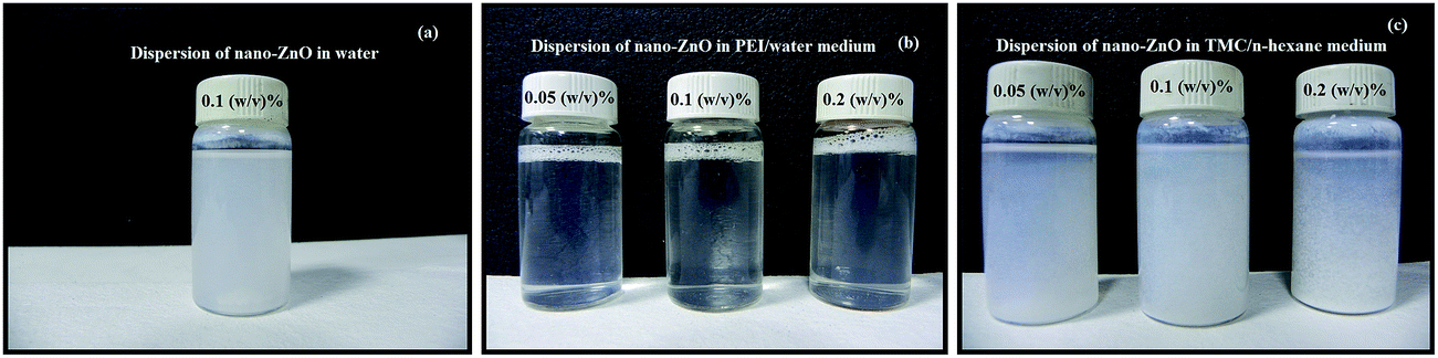 | ||
| Fig. 8 Photographs of nano-ZnO dispersion (a) in water (without PEI); (b) aqueous phase monomeric-PEI solutions; and (c) organic phase monomeric-TMC solutions containing different concentrations of nano-ZnO. | ||
Scanning electron micrographs of the skin layer as well as cross-sections of the Aq-ZnO:TFN-NF class of membranes are presented in Fig. 9a–c. Skin layer images show that the particles of nano-ZnO are well accommodated and evenly distributed inside the nanocomposite polyamide matrix of the membrane, formed through an interfacial polycondensation process. With increased concentration of the nano-ZnO from 0.05 to 0.2%, their density on the membranes' skin layers increase, which is supposed to perturb the polymeric chains through stretching and induce deformation in the network structure. As the nano-ZnO domains grow with increased concentration, they arrange themselves to form some long-range ordering and patterns indicating that extensive cohesive interactions occur between the nanomaterials themselves as well as between the nanomaterials and polymer chains. This pattern formation presumably occurs through multiple-point secondary chemical interactions between the nano-ZnO and the polyamide network which lead to a significant loss of translational entropy for the particles as well as conformational entropy for the polymeric chains. At higher nano-ZnO density of 0.2%, therefore, there are formation of a greater quantity of smaller coils of the nanomaterials in the polymer matrix to compensate for the entropy loss.60
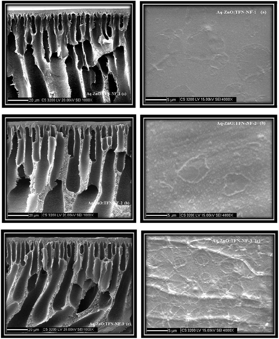 | ||
| Fig. 9 Cross-sectional and skin surface SEM images of Aq-ZnO:TFN-NF class of membranes made by introducing the nano-ZnO at different concentrations: (a) 0.05%, (b) 0.1%, and (c) 0.2%, through aqueous phase containing PEI. | ||
In contrast to the aqueous amine medium, the nano-ZnO is chemically incompatible in solution of n-hexane containing TMC and results in the formation of an unstable dispersion (Fig. 8c). The skin surface as well as cross-sectional SEM images of the Org-ZnO:TFN-NF class of membranes, prepared by introduction of nano-ZnO via the organic phase, are presented in Fig. 10a–c. Skin layer images show that the nanomaterials are not evenly distributed in the polymer matrix but rather present in the form of discrete clusters whose number and size increase with rising concentration of the nanomaterials in the organic phase. This indicates that the nanomaterials are unable to cohesively accommodate themselves within the polymer matrix when they are introduced through the organic phase. The orders and patterns found in the membranes of the Aq-ZnO:TFN-NF series are significantly missing. Since formation of the thin skin layer of the TFN-NF membrane takes place through cross-over of the PEI monomers from the aqueous phase to the organic side and across the polymer barrier (Fig. 1b), in a diffusion-controlled manner by the in situ interfacial polycondensation route,61 the nanomaterials do not find adequate opportunities to encounter a compatible polar environment to get evenly distributed before being embedded in the polyamide matrix. This results in an uneven distribution of the nano-ZnO in the form of uneven clusters in the resultant polyamide network.
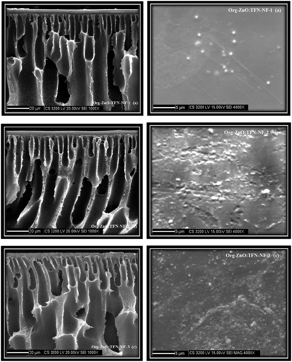 | ||
| Fig. 10 Cross-sectional and skin surface SEM images of Org-ZnO:TFN-NF class of membranes made by introducing nano-ZnO at different concentrations: (a) 0.05%, (b) 0.1%, and (c) 0.2%, through organic phase containing TMC. | ||
These observations through SEM studies emphasize the fact that the dynamics of skin layer formation through the interfacial polycondensation process, distribution of the nanomaterials within the skin layer and the resultant skin layer morphology of the nano-ZnO impregnated TFN-NF membranes are greatly influenced by the type of precursor media employed for dispersion of the nano-ZnO.
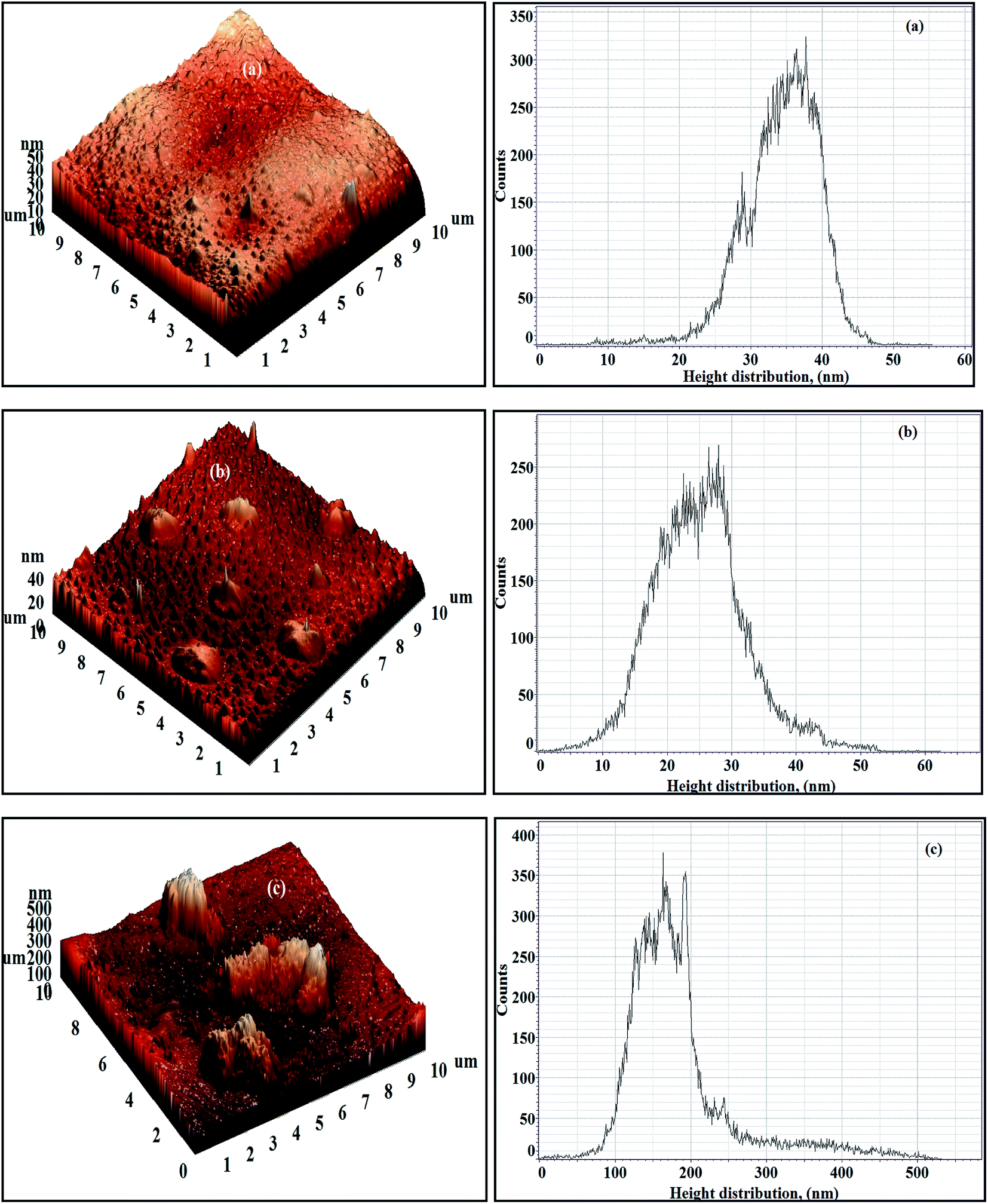
3.5 Evaluation of skin surface topographies of the TFN-NF membranes by AFM
The 3D AFM images as well as the respective height histograms of TFN-NF membranes, prepared by introducing nano-ZnO through the aqueous phase are presented in Fig. 11. They show that the surface topographies of the membranes change significantly from a relatively smooth profile for the membrane Aq-ZnO:TFN-NF-1 to progressively rougher surfaces for membranes made with impregnation of more and more nanomaterials. Further, pattern formations on membrane surfaces, a feature observed in the respective SEM images as well, justify the occurrence of long-range association of the nanomaterials in the polymer matrix. The 3D AFM images of Aq-ZnO:TFN-NF class of membranes, read along with the corresponding height histograms, show that the peaks are more or less uniform in height, having a very narrow distribution of 18–28 nm for Aq-ZnO:TFN-NF-1. However, in the case of Aq-ZnO:TFN-NF-2, the surface is seen to be populated with a larger number of peaks whose heights are significantly greater than those of Aq-ZnO:TFN-NF-1, with most occurring at 20–130 nm, contributing to a much broader distribution pattern. The greater area of the height histogram of Aq-ZnO:TFN-NF-2 also indicates a higher peakedness of this membrane compared to Aq-ZnO:TFN-NF-1, and consequently, an increased membrane surface area of the former membrane compared to the latter. With a still higher concentration of the nanomaterial in Aq-ZnO:TFN-NF-3, the peak heights of the membrane are far from uniform; their distribution is much wider and ranged between 10 to 270 nm. A significant tail in the height histogram suggests the presence of a few isolated high peaks with heights between 150 to 270 nm. As compared to Aq-ZnO:TFN-NF-2, where a number of narrow peaks are distributed over the entire surface of the membrane, the presence of higher concentration of nano-ZnO makes some of the isolated high peaks in Aq-ZnO:TFN-NF-3 quite broad.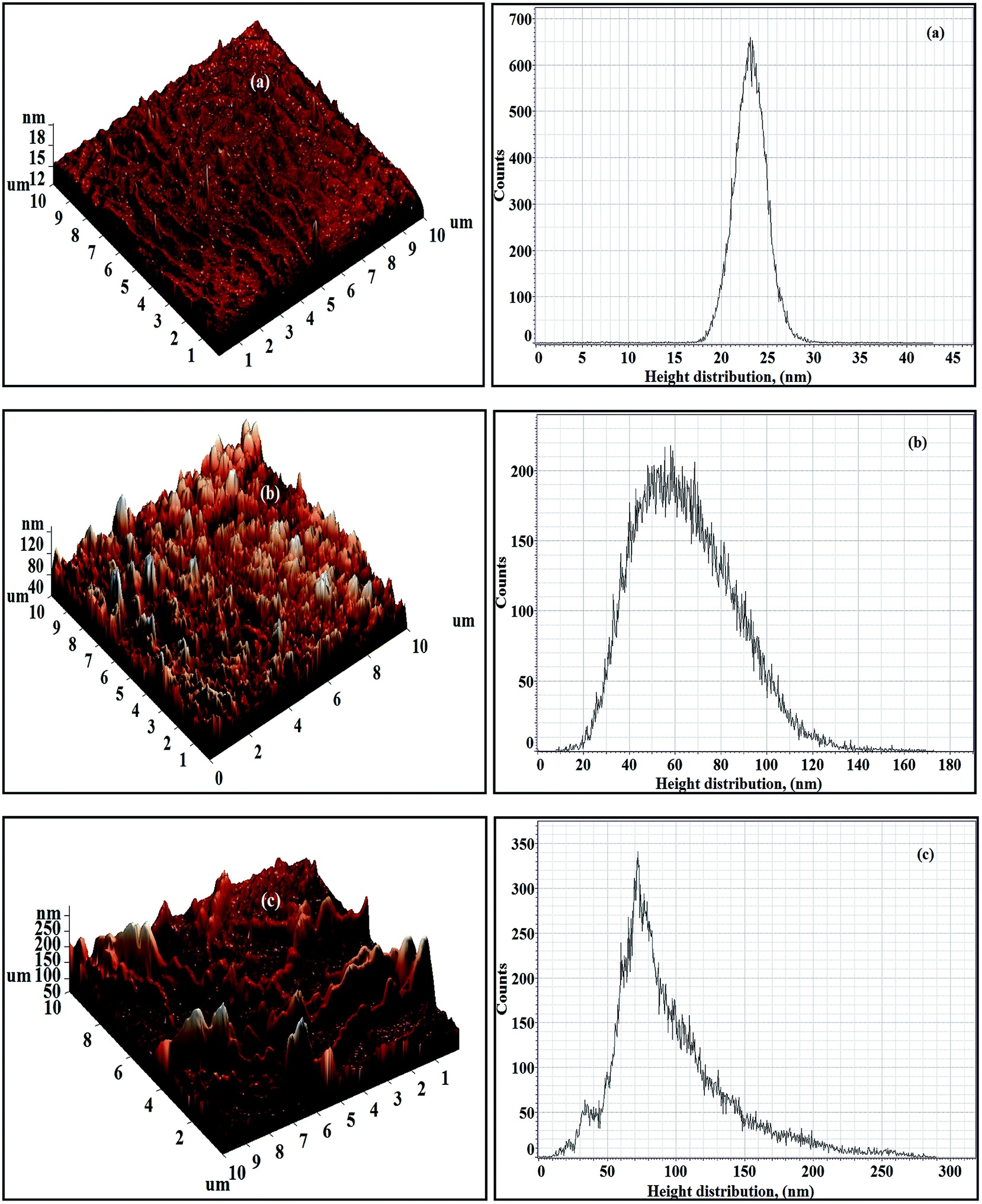 | ||
| Fig. 11 3D AFM images and height histograms of Aq-ZnO:TFN-NF class of membranes: (a) Aq-ZnO:TFN-NF-1, (b) Aq-ZnO:TFN-NF-2, and (c) Aq-ZnO:TFN-NF-3. | ||
The computed amplitude parameters of the nanocomposite membranes, presented in Table 2, show that the average roughness (Ra) of the membranes increases from 1.48 to 17.59 nm and further to 31.69 nm as concentration of nanomaterials in the aqueous monomer solution is increased. The corresponding root mean square roughness (Rq) of the membrane increases from 2.09 to 21.96 nm and finally to 41.96 nm. This is in accordance with the topographical features discussed in response to their 3D images. R10z, which is the difference in heights between the average of the five highest peaks and the five lowest valleys relative to the mean plane, denotes the contrast between the heights and depths of extreme peaks and valleys that may be occasionally present on the surface of the membrane. The lowest R10z value of 9.96 nm for Aq-ZnO:TFN-NF-1 results from a surface having peaks and valleys of less contrast in heights and depths. However, impregnation of a still higher amount of nanomaterials leads to higher values of R10z for Aq-ZnO:TFN-NF-2 (39.89 nm) and Aq-ZnO:TFN-NF-3 (101.57 nm), which indicates the occurrence of greater contrast in heights and depths due to the onset of isolated high peak and low valley formation on the membrane surface.
| Membrane code | Amplitude parameters | ||
|---|---|---|---|
| R a (nm) | R q (nm) | R 10z (nm) | |
| Aq-ZnO:TFN-NF-1 | 1.48 | 2.09 | 9.96 |
| Aq-ZnO:TFN-NF-2 | 17.59 | 21.96 | 39.89 |
| Aq-ZnO:TFN-NF-3 | 31.69 | 41.96 | 101.57 |
| Org-ZnO:TFN-NF-1 | 4.07 | 5.27 | 2.58 |
| Org-ZnO:TFN-NF-2 | 5.58 | 7.16 | 9.78 |
| Org-ZnO:TFN-NF-3 | 49.09 | 72.23 | 178.21 |
The 3D AFM images and height histograms of the Org-ZnO:TFN-NF class of membranes, prepared by introduction of nano-ZnO through the organic phase, presented in Fig. 12, show different types of surface topographies than the membranes prepared by introduction of the nanomaterials through the aqueous phase. The occurrence of long-range patterns due to distribution of nano-ZnO in the polymer nanocomposite, a characteristic of the latter class of membranes, is significantly absent. The nanomaterials, though found present throughout the membranes' skin surfaces in the form of discrete clusters, are not evenly distributed. The 3D images and the respective height histograms for Org-ZnO:TFN-NF-1 and Org-ZnO:TFN-NF-2 show that the number of peaks are fewer and their heights are much lower than for respective membranes in the aqueous phase. For the Org-ZnO:TFN-NF-1, the peak heights on the membrane surface are between 20 to 45 nm and, for Org-ZnO:TFN-NF-2, between 10 to 45 nm. However, for Org-ZnO:TFN-NF-3, the peak heights range between 100 to 500 nm, which is due to the presence of occasional high peaks on the surface of the membrane caused by entrapment of larger-sized clusters of nano-ZnO in the polyamide network.
 | ||
| Fig. 12 3D AFM images and height histograms of Org-ZnO:TFN-NF class of membranes: (a) Org-ZnO:TFN-NF-1, (b) Org-ZnO:TFN-NF-2, and (c) Org-ZnO:TFN-NF-3. | ||
The Ra values of the membranes, listed in Table 2, show that they are 4.07 and 5.58 nm, respectively, when 0.05 and 0.1% of the nano-ZnO are used. This nominal increase in roughness values is due to the absence of any significant number of peaks on the membrane surface, unlike their counterparts of the aqueous phase membranes. However, the Ra value increases to 49.09 nm in the membrane Org-ZnO:TFN-NF-3, which is believed to be due to the uneven distribution of the entrapped clusters of nanomaterials in the polymer matrix of the membrane. The variation in surface topography due to the effect of impregnation of nano-ZnO at progressively higher concentrations is also manifested through the change in Rq and R10z values.
The AFM studies have brought out the fact that surface roughness features such as formation and distribution, as well as variation of peaks and valleys, are highly influenced by the nature of the medium through which nanomaterials are impregnated into the skin layer of TFN-NF membranes.
3.6 Elemental analysis and mapping of TFN-NF membranes by EDX
The skin layer elemental mappings of both Aq-ZnO:TFN-NF and Org-ZnO:TFN-NF class of membranes presented in Fig. 13 and 14, respectively, show a differential distribution of the elements (N, Zn and O) within the bulk of the skin layer, with an increasing amount of nanomaterial impregnation. Elemental analysis of the Aq-ZnO:TFN-NF class of membranes by EDX, presented in Table 3 reveals that when the nano-ZnO concentration is increased from 0.05 to 0.1% and then to 0.2%, the relative nanoparticle density in the skin layer polyamide matrix increases from 2.48 ± 0.12 weight% (i.e., 0.64 atomic%) to 7.33 ± 0.13 weight% (i.e., 1.83 atomic%) and finally to 10.02 ± 0.29 weight% (i.e., 3.65 atomic%). The corresponding values of relative atomic ratios of the unique elements Zn and N (i.e., Zn:N) in the skin layers of these membranes show an increasing trend from 1:44.02 to 1:7.24 through 1:15.04.
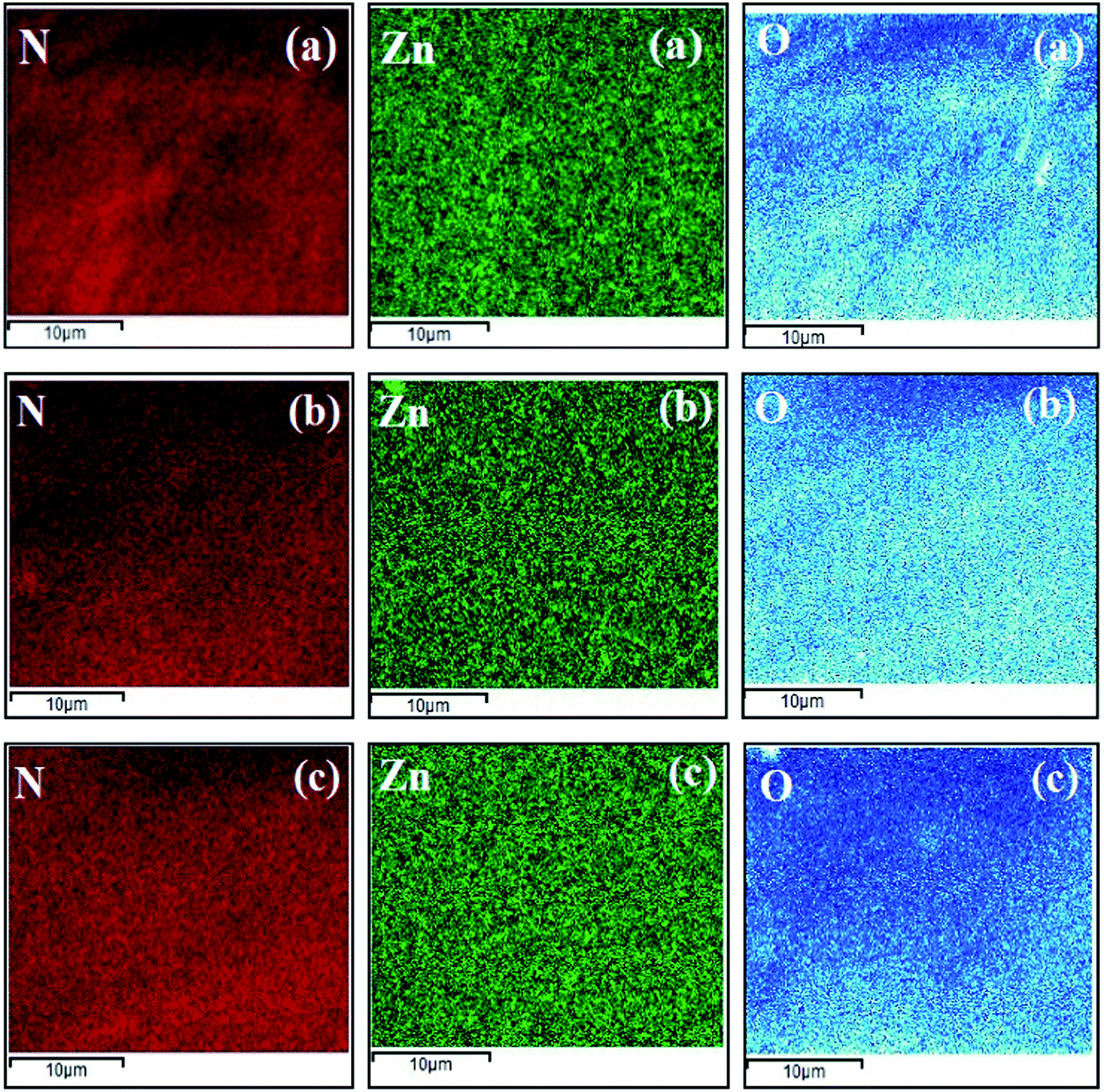 | ||
| Fig. 13 Elemental mapping of nanocomposite polyamide skin layers of Aq-ZnO:TFN-NF class of membranes: (a) Aq-ZnO:TFN-NF-1, (b) Aq-ZnO:TFN-NF-2, and (c) Aq-ZnO:TFN-NF-3. | ||
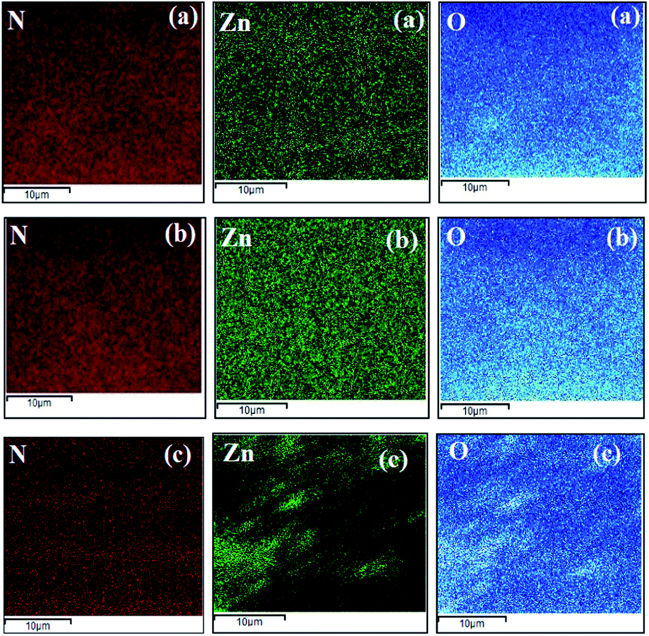 | ||
| Fig. 14 Elemental mapping of nanocomposite polyamide skin layers of Org-ZnO:TFN-NF class of membranes: (a) Org-ZnO:TFN-NF-1, (b) Org-ZnO:TFN-NF-2, and (c) Org-ZnO:TFN-NF-3. | ||
| Membrane code | Elemental (N) quantification | Elemental (O) quantification | Elemental (Zn) quantification | Relative atomic ratio (Zn/N) | |||
|---|---|---|---|---|---|---|---|
| Wt (%) | Atomic (%) | Wt (%) | Atomic (%) | Wt (%) | Atomic (%) | ||
| Aq-ZnO:TFN-NF-1 | 25.01 ± 0.16 | 28.17 | 72.51 ± 0.147 | 71.19 | 2.48 ± 0.12 | 0.64 | 1:44.02 |
| Aq-ZnO:TFN-NF-2 | 23.57 ± 0.17 | 27.52 | 69.10 ± 0.19 | 70.65 | 7.33 ± 0.13 | 1.83 | 1:15.04 |
| Aq-ZnO:TFN-NF-3 | 22.73 ± 0.42 | 26.42 | 67.25 ± 0.25 | 69.93 | 10.02 ± 0.29 | 3.65 | 1:7.24 |
| Org-ZnO:TFN-NF-1 | 24.87 ± 0.68 | 28.05 | 72.08 ± 0.80 | 71.13 | 3.05 ± 0.59 | 0.82 | 1:34.21 |
| Org-ZnO:TFN-NF-2 | 22.98 ± 0.28 | 27.24 | 67.86 ± 0.32 | 70.43 | 9.16 ± 0.20 | 2.33 | 1:11.69 |
| Org-ZnO:TFN-NF-3 | 20.52 ± 0.51 | 26.07 | 62.91 ± 0.33 | 69.53 | 16.57 ± 0.29 | 4.40 | 1:5.93 |
However, the increase in respective values of the Org-ZnO:TFN-NF class of membranes is much higher. The nano-ZnO density increases from 3.05 ± 0.59 weight% (i.e., 0.82 atomic%) to 9.16 ± 0.20 weight% (i.e., 2.33 atomic%), and then to as high as 16.57 ± 0.29 weight% (i.e., 4.40 atomic%) with the introduction of 0.05, 0.1 and 0.2% of nano-ZnO, respectively. Similarly, the relative atomic ratios of the unique elements Zn and N of these membranes increase from 1:34.21 to 1:11.69, and finally to 1:5.93, indicating incorporation of progressively greater quantities of nano-ZnO in the nanocomposite polyamide skin layer. The determined elemental ratios of the unique elements may not refer only to composition of the skin layer (∼500 nm), but also imply the contribution of these elements residing underneath the polyamide layer, i.e., the polysulfone layer (∼3 μm).
Impregnations of larger quantities of nano-ZnO in the skin layer of the latter class of membranes have also been observed during respective SEM and AFM analyses. This occurs because during progress of the heterogeneous type interfacial polycondensation reaction and successive formation of the nascent polymer layer, the migrating reactant PEI met the reactant of the organic phase, i.e., TMC (with or without nano-ZnO, as the case may be) in the organic phase (Fig. 1) close to the boundary between the mutually immiscible solvents. In this situation, when the nanomaterials are present in the organic phase, greater quantities of nano-ZnO are likely in the reaction zone during the process of polycondensation reaction. The unstable dispersion of the nanomaterial in the organic medium may further be responsible for some deposition and subsequent entrapment of the nano-ZnO in the skin layer of the membrane. But, when the nano-ZnO becomes a constituent of the aqueous amine phase, the monomer along with nano-ZnO has to cross the barrier of the nascent polyamide film and approach the reactants of the organic phase to undergo further polymerization. The transport of nano-ZnO in the reaction zone may not be facilitated because the rate of diffusion across the nascent polymeric barrier for the bulky-sized nano-ZnO associated PEI of the aqueous amine phase becomes comparatively slow. This may be responsible for the lower quantity of nano-ZnO in the skin layer polyamide of the Aq-ZnO:TFN membrane class.
3.7 Evaluation of transport characteristics of TFN-NF membranes
The solute rejection behaviors of the Aq-ZnO:TFN-NF class of membranes as well as that of the Control-NF (see Fig. 15a) show that the TFN-NF membranes give much higher rejections for MgCl2 than for NaCl and Na2SO4, which follows the general trend MgCl2 > NaCl ≥ Na2SO4. This implies that the membranes are inherently positively charged, which is characteristic of membranes derived using PEI. With greater concentration of nano-ZnO in the membranes' skin layers there is a decline in the differential rejection among these three solutes, more specifically between MgCl2 and Na2SO4. Their solute rejection ratios of 92.3:51.3, 87.6:50.2 and 84.2:48.4 indicate the possibility of decrease in the surface positive charge of the membranes with enhanced incorporation of nano-ZnO in the nanocomposite matrix. However, this may not be the sole reason for the trend since morphological factors, especially the possible formation of a more open polymer matrix that further influences the porous nature of the nanocomposite membranes, may have contributed to an overall decline of SR values for all solutes. In these positively charged membranes, the maximum solute rejection for MgCl2 is predominantly governed by Donnan exclusion: due to the presence of multivalent cation (Mg2+) with a higher positive charge density, the solute experiences maximum electrostatic repulsion by the charged membranes.62–64 A lower solute rejection of NaCl results from a weaker Donnan exclusion of the monovalent Na+ ions by the membrane. However, the presence of bivalent anions in Na2SO4 facilitates its transport through the membrane, further reducing the respective solute rejection.
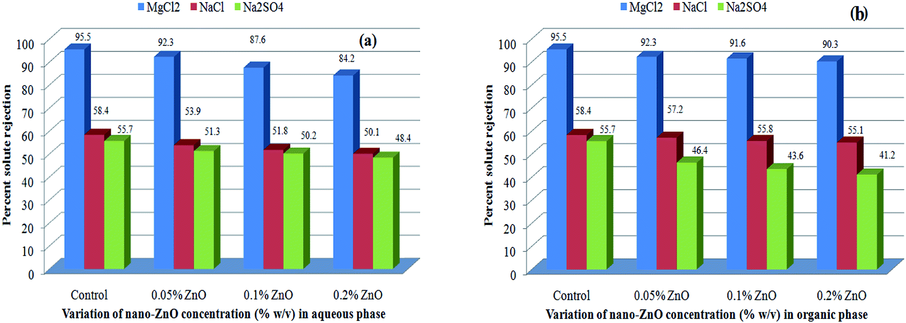 | ||
| Fig. 15 Effect of variation of nano-ZnO concentration on solute rejection behaviors of (a) Aq-ZnO:TFN-NF and (b) Org-ZnO:TFN-NF class of membranes. | ||
A similar order of solute rejection pattern, MgCl2 > NaCl ≥ Na2SO4, for the Org-ZnO:TFN-NF class of membranes, however, comes with a superior differential rejection ability between MgCl2 and Na2SO4, as compared to the Aq-ZnO:TFN-NF class of membranes (Fig. 15b). This signifies a higher positive charge of the Org-ZnO:TFN-NF class of membranes, the origin of which has been discussed during characterization of the skin layers of the membranes via FTIR as well as XPS. Consequently, the solute rejection ratios for MgCl2 and Na2SO4 of the Org-ZnO:TFN-NF-1, Org-ZnO:TFN-NF-2 and Org-ZnO:TFN-NF-3 show an increasing trend, i.e., 92.3:46.4, 91.6:43.6 and 90.3:41.2, respectively. However, decline in the solute rejections for the Org-ZnO:TFN-NF class of membranes, with increased concentration of nano-ZnO beyond 0.05%, is not as pronounced as for the Aq-ZnO:TFN-NF class of membranes.
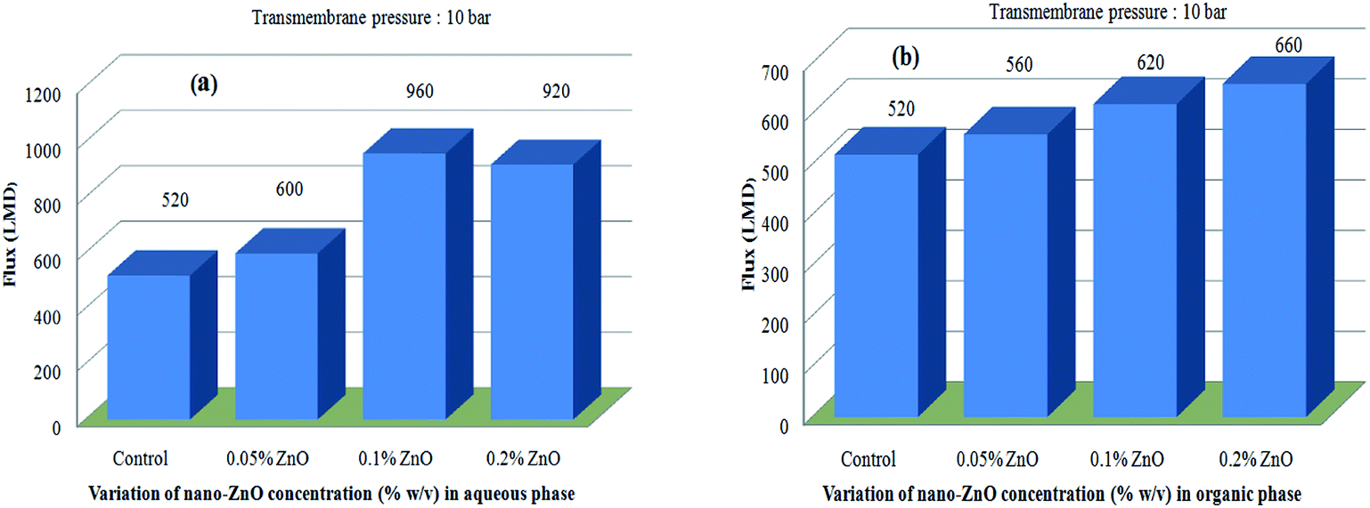
Both classes of TFN-NF membranes showed significant increases in their solvent fluxes, with the progressive impregnation of nano-ZnO in making the membranes. Solvent fluxes for the representative solute MgCl2 increase from 520 LMD for Control-NF to 600 LMD for Aq-ZnO:TFN-NF-1, 960 LMD for Aq-ZnO:TFN-NF-2 and 920 LMD for Aq-ZnO:TFN-NF-3 (Fig. 16a). Similarly, the solvent fluxes increased from 520 LMD for Control-NF to 560 LMD for Org-ZnO:TFN-NF-1, 620 LMD for Org-ZnO:TFN-NF-2 and finally to 660 LMD for Org-ZnO:TFN-NF-3 (Fig. 16b). The increase of solvent fluxes in the TFN class of membranes has been widely reported in the literature: the improvement is attributed to the presence of nanomaterials in the interfacial reaction zone, which influences the kinetics of the interfacial polycondensation reaction by factors such as change in miscibility of the aqueous and organic phases through released heat of hydration of the nanomaterials, change in the diffusion rate of monomers that consequently alters the cross-linking density of the polymer network, and the hydrophilic/hydrophobic nature of the membrane surfaces.65–67
 | ||
| Fig. 16 Effect of variation of nano-ZnO concentration on permeate flux behaviors of (a) Aq-ZnO:TFN-NF and (b) Org-ZnO:TFN-NF class of membranes. | ||
For the Org-ZnO:TFN-NF class of membranes, the free PEI molecules (since aqueous amine medium of this class is devoid of the nano-ZnO) experience greater mobility and diffusivity to migrate from aqueous to the organic phase, across the nascent polymer layer, which ensures an enhanced rate of polymerization in the reaction zone. Also, the heat of hydration of nano-ZnO, which was present in considerable density in the organic phase, could induce increased local temperature in the reaction zone as the nanoparticles encounter the hydrated PEI molecules. This thermal impact can additionally contribute to improving the miscibility of the two heterogeneous phases locally, and subsequently facilitate the reaction by enhancing the rate of diffusion of the PEI monomers into the organic phase.65 Such thermal effects may have some influence in the exothermic type polycondensation reaction to reduce reactivity. Thus, it can be assumed that impregnation of more nano-ZnO tunes the reaction in such a manner that it becomes kinetically more favourable, while simultaneously thermodynamically adverse. However, the overall effect results in formation of a skin layer with a cross-linked polymer network featuring enhanced solvent permeability. Meanwhile, as manifested from the morphological and topographical analyses, the nanomaterials are less uniformly distributed in the skin layer matrix of the membrane, forming rather discrete clusters due to an unstable dispersion of nanomaterials in the organic monomeric phase (Fig. 8c). These factors lead to a nanocomposite polymer layer where the clusters of nano-ZnO might block some channel entrances for solvent flow in the membranes, resulting in a lower increase of solvent fluxes for the Org-ZnO:TFN-NF class of membranes as compared to the Aq-ZnO:TFN-NF class of membranes.68,69
In the case of the Aq-ZnO:TFN-NF class of membranes, the bulky nature of the nano-ZnO-associated PEI molecules in the aqueous phase leads to restricted mobility and a slow rate of diffusion of the monomer from the aqueous to organic phase across the nascent interfacial polymer layer resulting in reduced reactivity, which may in turn lead to kinetic inhibition in growth of the polymer film. Further, an open structure in the polymer network as described in the SEM analysis and a probable increase in the membranes' pore sizes—reflected in the reduced solute rejection—make the flow of solvent easier.70,71 The significant peakedness of the membrane observed in respective AFM images due to nanomaterial incorporation is also supposed to increase the membranes' effective surface area. These factors collectively account for increased solvent fluxes of these membranes prepared by introducing nano-ZnO through the aqueous phase. However, a reduced solute rejection with no accompanying increase in solvent flux for the Aq-ZnO:TFN-NF-3 indicates that the increased concentration of the nano-ZnO at this level may have acted as a pore blocker residing within the channels of solvent flow, thereby hindering solvent flow through this membrane, while simultaneously introducing defects in the membrane skin layer that lowered its solute rejection ability.
4. Conclusions
TFN-NF membranes with nano-ZnO-impregnated polyamide matrices were prepared following different routes to impregnate the nanomaterial during in situ interfacial polymerization of reactive monomers. Effects of variation in the route-specific introduction of nano-ZnO into the skin layer polymer matrix through either the aqueous or organic phase route were evaluated extensively by instrumental techniques. Structural characterizations by XPS and ATR FTIR have probed the interactions of the nano-ZnO and its coexistence in the hybrid nanocomposite material. Morphological and topographical characterizations by SEM and AFM revealed that adoption of these routes yielded membranes with distinctly different surface features. The uniformity in distribution of the nano-ZnO was lower in the skin surface of Org-ZnO:TFN-NF membranes than when they were introduced through the aqueous phase. The distinctly positively charged membranes provided differential solute rejections for solutes having varying combinations of cations and anions in the order of MgCl2 > NaCl ≥ Na2SO4. Introduction of nano-ZnO improved the solvent fluxes of the membranes significantly, particularly in the Aq-ZnO:TFN-NF set of membranes. We have established correlations between the factors leading to dynamic membrane formation and the resulting physicochemical features as well as transport properties.Notes and references
- M. Mulder, Basic Principles of Membrane Technology, Kluwer Academic Publishers, Netherlands, 2nd edn, 1998 Search PubMed.
- R. J. Peterson, J. Membr. Sci., 1993, 83, 81–150 CrossRef.
- A. E. Childress and M. Elimelech, J. Membr. Sci., 1996, 119, 253–268 CrossRef CAS.
- D. X. Wang, M. Su, Z. Y. Yu, X. L. Wang, M. Ando and T. Shintani, Desalination, 2005, 175, 219–225 CrossRef CAS.
- B. Al-Rashdi, C. Somerfield and N. Hilal, Sep. Purif. Rev., 2011, 40, 209–259 CrossRef CAS.
- B. Balannec, M. Yourch, M. R. Baudry and B. Chayfer, Sep. Purif. Technol., 2005, 42, 195–200 CrossRef CAS.
- J. Radjenovic, M. Petrovic, F. Ventura and D. Barcelo, Water Res., 2008, 42, 3601–3610 CrossRef CAS PubMed.
- N. Capelle, P. Moulin, F. Charbit and R. Gallo, J. Membr. Sci., 2002, 196, 125–141 CrossRef CAS.
- C. Tang and V. Chen, Desalination, 2002, 143, 11–20 CrossRef CAS.
- S. J. Sarrade, G. M. Rios and M. Carlès, Sep. Purif. Technol., 1998, 14, 19–25 CrossRef CAS.
- B. H. Jeong, E. M. V. Hoek, Y. Yan, A. Huang, X. Subramani, G. Hurwitz, A. K. Ghosh and A. Jawor, J. Membr. Sci., 2007, 294, 1–7 CrossRef CAS.
- S. Y. Kwak, S. H. Kim and S. S. Kim, Environ. Sci. Technol., 2001, 35, 2388–2394 CrossRef CAS PubMed.
- S. Sorribas, P. Gorgojo, C. Téllez, J. Coronas and A. G. Li, J. Am. Chem. Soc., 2013, 40, 15201–15208 CrossRef PubMed.
- M. G. Buonomenna, Desalination, 2013, 314, 73–88 CrossRef CAS.
- J. Shen, H. Ruan, L. Wu and C. Gao, Chem. Eng. J., 2011, 168, 1272–1278 CrossRef CAS.
- J. Huang, K. Zhang, K. Wang, Z. Xie, B. Ladewig and H. Wang, J. Membr. Sci., 2012, 423–424, 362–370 CrossRef CAS.
- N. Maximous, G. Nakhla, W. Wan and K. Wong, J. Membr. Sci., 2009, 341, 67–75 CrossRef CAS.
- N. Maximous, G. Nakhla, K. Wong and W. Wan, Sep. Purif. Technol., 2010, 73, 294–301 CrossRef CAS.
- H. S. Lee, S. J. Im, J. H. Kim, H. J. Kim, J. P. Kim and B. R. Min, Desalination, 2008, 219, 48–56 CrossRef CAS.
- Y. Mansourpanah, S. S. Madaeni, A. Rahimpour, A. Farhadian and A. H. Taheri, J. Membr. Sci., 2009, 330, 297–306 CrossRef CAS.
- J. H. Li, Y. Y. Xu, L. P. Zhu, J. H. Wang and C. H. Du, J. Membr. Sci., 2009, 326, 659–666 CrossRef CAS.
- M. Sairam, B. V. K. Naidu, S. K. Nataraj, B. Sreedhar and T. M. Aminabhavi, J. Membr. Sci., 2006, 283, 65–73 CrossRef CAS.
- C. P. Leo, W. P. C. Lee, A. L. Ahmad and A. W. Mohammad, Sep. Purif. Technol., 2012, 89, 51–56 CrossRef CAS.
- L. Shen, X. Bian, X. Lu, L. Shi, Z. Liu, L. Chen, Z. Hou and K. Fan, Desalination, 2012, 293, 21–29 CrossRef CAS.
- M. L. Lind, D. E. Suk, T. V. Nguyen and E. M. V. Hoek, Environ. Sci. Technol., 2010, 44, 8230–8235 CrossRef CAS PubMed.
- M. L. Lind, A. K. Ghosh, A. Jawor, X. Huang, W. Hou, Y. Yang and E. M. V. Hoek, Langmuir, 2009, 25, 10139–10145 CrossRef CAS PubMed.
- Z. Emami-Karvani and P. Chehrazi, Afr. J. Microbiol. Res., 2011, 5, 1368–1373 CAS.
- J. Sawai, J. Microbiol. Methods, 2003, 54, 177–182 CrossRef CAS PubMed.
- M. Yan, Y. Song, C. P. Wong, K. Hardin and E. Ho, J. Nutr., 2008, 138, 667–673 CAS.
- L. K. Adams, D. Y. Lyon and P. J. J. Alvarez, Water Res., 2006, 40, 3527–3532 CrossRef CAS PubMed.
- R. Brayner, R. Ferrari-Iliou, N. Brivois, S. Djediat, M. F. Benedetti and F. Fiévet, Nano Lett., 2006, 6, 866–870 CrossRef CAS PubMed.
- H. A. Jeng and J. Swanson, J. Environ. Sci. Health, Part A: Toxic/Hazard. Subst. Environ. Eng., 2006, 41, 2699–2711 CrossRef CAS PubMed.
- K. R. Raghupathi, R. T. Koodali and A. C. Manna, Langmuir, 2011, 27, 4020–4028 CrossRef CAS PubMed.
- N. Jones, B. Ray, K. T. Ranjit and A. C. Manna, FEMS Microbiol. Lett., 2008, 279, 71–76 CrossRef CAS PubMed.
- J. M. Yousef and E. N. Danial, J. Health Sci., 2012, 2, 38–42 Search PubMed.
- G. Rudolph and M. C. Henry, Inorg. Synth., 1967, 10, 74 CrossRef CAS.
- E. S. Gadelmawla, M. M. Koura, T. M. A. Maksoud, I. M. Elewa and H. H. Soliman, J. Mater. Process. Technol., 2002, 123, 133–145 CrossRef.
- R. Elilarassi and G. Chandrasekaran, Mater. Chem. Phys., 2010, 123(2–3), 450–455 CrossRef CAS.
- T. C. Damen, S. P. S. Porto and B. Tell, Phys. Rev., 1966, 142, 570–574 CrossRef CAS.
- Y. J. Xing, Z. H. Xi, Z. Q. Xue, X. D. Zhang, J. H. Song, R. M. Wang, J. Xu, Y. Song, S. L. Zhang and D. P. Yu, Appl. Phys. Lett., 2003, 83, 1689–1691 CrossRef CAS.
- A. Umar and Y. B. Hahn, Appl. Phys. Lett., 2006, 88, 173120–173122 CrossRef.
- I. Calizo, A. K. Alim, V. A. Fonoberov, S. Krishnakumar, M. Shamsa, A. A. Balandin and R. Kurtz, Proc. of SPIE 2007, 6481, Quantum Dots, Particles, and Nanoclusters IV, 64810N-1– 64810N-8.
- A. A. Ashkarran, S. M. Mahdavi and M. M. Ahadian, Appl. Phys. A: Mater. Sci. Process., 2010, 100, 1097–1102 CrossRef CAS.
- Z. Li, Y. Xiong and Y. Xie, Inorg. Chem., 2003, 42(24), 8105–8109 CrossRef CAS PubMed.
- X. Zhang, J. Qin, Y. Xue, P. Yu, B. Zhang, L. Wang and R. Liu, Sci. Rep., 2014, 4, 4596 Search PubMed.
- H. S. Shin, H. C. Choi, Y. Jung, S. B. Kim, H. J. Song and H. J. Shin, Chem. Phys. Lett., 2004, 383, 418–422 CrossRef CAS.
- C. N. R. Rao, V. Vijayakrishnan, N. H. Aiyer, G. U. Kulkarni and G. N. Subbanna, J. Phys. Chem., 1993, 97, 11157–11160 CrossRef CAS.
- G. K. Wertheim, Z. Phys. B: Condens. Matter, 1987, 66, 53–63 CrossRef CAS.
- D. H. Shin, N. Kim and Y. T. Lee, J. Membr. Sci., 2011, 376, 302–311 CrossRef CAS.
- M. J. Ariza, E. R. Castellón, R. Rico, J. Benavente, M. Muñoz and M. Oleinikova, J. Colloid Interface Sci., 2000, 226, 151–158 CrossRef CAS PubMed.
- D. Maity and J. Ding, Int. J. Nanosci., 2011, 10, 943–947 CrossRef CAS.
- K. Namratha, M. B. Nayan and K. Byrappa, Mater. Res. Innovations, 2011, 15, 36–42 CrossRef CAS.
- S. Liufu, H. Xiao and Y. Li, Powder Technol., 2004, 145, 20–24 CrossRef CAS.
- T. Takagishi, S. Okuda and N. Kuroki, J. Polym. Sci., Part A: Polym. Chem., 1985, 23, 2109–2116 CrossRef CAS.
- D. J. Skrovanek, P. C. Painter and M. M. Coleman, Macromolecules, 1986, 19(3), 699–705 CrossRef CAS.
- E. Rusu, G. Rusu and D. O. Dorohoi, Polimery, 2009, 54, 347–353 CAS.
- K. J. Kamer, A. Choudhary and R. T. Raines, J. Org. Chem., 2013, 78, 2099–2103 CrossRef CAS PubMed.
- B. Faure, G. Salazar-Alvarez, A. Ahniyaz, I. Villaluenga, G. Berriozabal, Y. R. De Miguel and L. Bergström, Sci. Technol. Adv. Mater., 2013, 14, 023001 CrossRef.
- G. Fritz, V. Schädler, N. Willenbacher and N. J. Wagner, Langmuir, 2002, 18, 6381–6390 CrossRef CAS.
- R. Shenhar, T. B. Norsten and V. M. Rotello, Adv. Mater., 2005, 17(6), 657–669 CrossRef CAS.
- T. M. Frunze, V. V. Kurashev and L. V. Kozlov, Russ. Chem. Rev., 1961, 30, 252–270 CrossRef.
- T. K. Dey, R. C. Bindal, S. Prabhakar and P. K. Tewari, Sep. Sci. Technol., 2011, 46, 933–943 CrossRef CAS.
- J. M. M. Peeters, J. P. Boom, M. H. V. Mulder and H. Strathmann, J. Membr. Sci., 1998, 145, 199–209 CrossRef CAS.
- M. R. Teixeira, M. J. Rosa and M. Nystrom, J. Membr. Sci., 2005, 265, 160–166 CrossRef CAS.
- M. L. Lind, B. H. Jeong, A. Subramani, X. Huang and E. M. V. Hoek, J. Mater. Res., 2009, 24, 1624–1631 CrossRef CAS.
- H. Huang, X. Qu, H. Dong, L. Zhang and H. Chen, RSC Adv., 2013, 3, 8203–8207 RSC.
- T. A. Ostomel, P. K. Stoimenov, P. A. Holden, H. B. Alam and G. D. Stucky, J. Thromb. Thrombolysis, 2006, 22, 55–67 CrossRef CAS PubMed.
- J. Yin, E. S. Kim, J. Yang and B. Deng, J. Membr. Sci., 2012, 423–424, 238–246 CrossRef CAS.
- R. X. Zhang, L. Braeken, P. Luis, X. L. Wang and B. Van der Bruggen, J. Membr. Sci., 2013, 437, 179–188 CrossRef CAS.
- B. Rajaeian, A. Rahimpour, M. O. Tade and S. Liu, Desalination, 2013, 313, 176–188 CrossRef CAS.
- G. L. Jadav and P. S. Singh, J. Membr. Sci., 2009, 328, 257–267 CrossRef CAS.
| This journal is © The Royal Society of Chemistry 2015 |