Super flexible, highly conductive electrical compositor hybridized from polyvinyl alcohol and silver nano wires
Hui-Wang Cui*a,
Jin-Ting Jiua,
Katsuaki Suganumaa and
Hiroshi Uchidab
aInstitute of Scientific and Industrial Research, Osaka University, Mihogaoka 8-1, Ibaraki, Osaka 567, Japan. E-mail: cuihuiwang@hotmail.com
bInstitute for Polymers and Chemicals Business Development Center, Showa Denko K. K., 5-1 Yawata Kaigan Dori, Ichihara, Chiba 290-0067, Japan
First published on 19th December 2014
Abstract
A biodegradable polyvinyl alcohol and silver nanowires (AgNWs) have been mixed together with a simple one-step blending method to form a hybrid electrical compositor. Super flexible and highly conductive electrical compositors were successfully developed with an AgNWs content of 80%, in which hundreds, even thousands of AgNWs stacked into a “Chrysanthemum petal” order to exhibit high electrical conductivity of 17![[thin space (1/6-em)]](https://www.rsc.org/images/entities/char_2009.gif) 390 S cm−1. The high conductivity corresponded to the formation of a large amount of electrically conductive networks and channels. The conductively electrical compositor can be made into various shapes and can be used on any substrate with different curved surfaces because the compositor ink is so stable and can be stored for a long time without other additives. The compositor is expected to have great potential application in flexible electronics, especially in those fields associated with biology, medicine, food, and life.
390 S cm−1. The high conductivity corresponded to the formation of a large amount of electrically conductive networks and channels. The conductively electrical compositor can be made into various shapes and can be used on any substrate with different curved surfaces because the compositor ink is so stable and can be stored for a long time without other additives. The compositor is expected to have great potential application in flexible electronics, especially in those fields associated with biology, medicine, food, and life.
Introduction
Flexible electronics (e.g., stretchable displays,1,2 flexible radiofrequency antennas,3,4 artificial muscles,5,6 implantable devices,7,8 wearable electronics,9,10 smart clothes,11,12 and sensory skin for robotic system7,8), a form of electronics that can be bended, twisted, folded, and stretched, hold promise to open up unprecedented applications, which are unreachable with existing rigid technology. A number of different approaches have been proposed for the preparation of such materials, e.g., wavy thin metals,13,14 metal-coated net-shaped plastic films,15,16 graphene films,17,18 and carbon nanotube based composites,19,20 etc. As one of the most important conductive materials, silver nanowires (AgNWs) have recently attracted a lot of attention for potential application as transparent electrodes.21–23Lately, AgNWs have been used to make flexible electrodes due to the large aspect ratio. Xu et al. drop-casted AgNWs suspension onto a precleaned substrate (e.g., silicon wafer, glass slide, or plastic materials), the AgNWs were then dried to form a uniform and conductive film of AgNWs network with thickness ranging from one to several micrometers; next, liquid poly(dimethylsiloxane) (PDMS) was casted on top of the AgNWs film, followed by curing at 65 °C for 12 h; when peeled off the substrate, the AgNWs film was bonded to the cured and soft and flexible PDMS to form a conductive and stretchable layer.24 Ge et al. used a commercially available polyurethane (PU) sponges with 3D-interconnected microfiber networks as a skeleton template; after being dipped into an ethanol solution of the AgNWs, the bare PU sponges were fully infiltrated by the ethanol solution of AgNWs, the hydrophilic surface of the microfibers and the unique macroporous of sponges guaranteed the formation of a conductive sponge with binary AgNWs nano/micro-network structures; finally, PDMS was introduced into the PU–AgNWs conductive sponges to form the desired PU–AgNWs–PDMS stretchable conductors, and the PU microfibers and AgNWs were both well encapsulated by PDMS and yielded well-defined binary nano/micro-scale network structures.25 Yan et al. prepared two sets of filtration masks for AgNWs electrodes and ZnO nanowires (ZnONWs) channel from cured PDMS; the mask for electrodes was first put on top of the polycarbonate filter membrane, the AgNWs dispersions were filtrated to get a uniform percolating nanowire film, then the first mask was removed and the AgNWs film was thoroughly rinsed with ethanol; the second mask for ZnO channel was aligned on top of the AgNWs electrode patterns, and the ZnONWs patterns were filtered analogously; the filter membrane with AgNWs and ZnONWs patterns was then placed in a glass Petri dish, and liquid PDMS was poured on top of the membrane, degassed for 30 min in a vacuum desiccator and cured at 60 °C for 2 h; as the PDMS was peeled off from the filter membrane after solidification with both nanowire electrodes and channels transferred into the PDMS matrix, the stretchable nanowire photodetector arrays made of two symmetric AgNWs electrodes and one ZnONWs detection channel were obtained.26 Apparently, the PDMS has been used as transfer printing stamps and can produce stretchable substrates and embedded structures, as aforementioned reports; the AgNWs electrodes depend on the PDMS substrate greatly from which the stretchability and flexibility mainly originate, and the preparation is too complex that already have limited the development of electrical compositor for flexible electronics significantly. Moreover, such reports all ignore the preparations of hybrid electrical compositors using AgNWs as additives. If a simple blending method between AgNWs and polymers can be developed, this will simplify the formation process and extend the applications of flexible electronics.
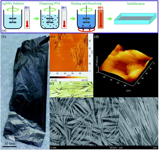
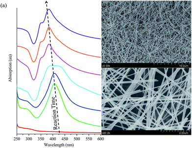
Herein, we reported a simple one-step blending method [Fig. 1(a)] for hybrid AgNWs/polyvinyl alcohol (AgNWs/PVA) electrical compositor with high performances (e.g., super flexibility, highly electrical conductivity) [Fig. 1(b)]. PVA is a thermoplastic polymer with a simple linear structure, containing a large amount of active hydroxyl groups, also is a biodegradable polymeric material.27,28 AgNWs were synthesized in a large scale according to the previously reported polyol procedures.23,29,30 As the reaction time lengthened, the AgNWs were gradually generated and presented a strong UV absorption peak near 380 nm [Fig. 2(a)]; the AgNWs were ≥60 μm and even 100 μm in length [Fig. 2(b)]. AgNWs were dispersed in water to form a 0.5% suspension solution, which can be easily blended with PVA water solution at any ratio; therefore, a homogenous mixture solution was simply obtained. The AgNWs in the PVA matrix had eventually developed into order arrangements at high AgNWs contents [Fig. 1(c), (d), (f), and (g)] like Chrysanthemum petals [Fig. 1(e)].31 Moreover, the AgNWs/PVA electrical compositors showed super flexibility that can be made into various shapes, can be used on any substrate and any curved surface, can be used as smart textiles and electronic skins, which will more facilitate flexible electronics in biological, medical, food, and life fields.
Experiments
Samples
The electrical compositor consisted of a polymeric matrix and electrically conductive fillers. The polymeric matrix was a white granular JC-33 PVA from Japan VAM & POVAL Co., Ltd., Osaka, Japan: the non-volatile content at 96.40%, degree of polymerization at 3300, degree of hydrolysis at 99.19 mol%, viscosity at 111 mPa s (4% solution, 20 °C), and pH at 6 (4% solution, 20 °C). The electrically conductive fillers were AgNWs, prepared according to the previously reported polyol procedures;23,29,30 the diameter was about 60 nm and the length more than 60 μm [Fig. 2(b)]. The obtained AgNWs were dispersed in deionized water, forming a 0.5% suspension solution by the weight for further use. The fabrication process of the AgNWs/PVA electrical compositor is schematically illustrated in Fig. 1(a). PVA was firstly dispersed into 40 g of AgNWs suspension solution at room temperature under an intensely mechanical stirring. Then the temperature increased to about 95 °C. Keeping this temperature and stirring for about 2 h, about 5 g of the mixture was taken out and poured into a plastic model (80 mm × 80 mm). After solidified at room temperature for 1 day, the AgNWs/PVA electrical compositor was obtained [Fig. 1(b)]. In the fabrication, the AgNWs suspension solution was fixed at 40 g, the added PVA was 4, 2, 1, 0.75, 0.5, 0.4, 0.3, 0.2, 0.1, and 0.05 g, respectively, corresponding to the AgNWs contents at 4.76%, 9.09%, 16.67%, 21.05%, 28.57%, 33.33%, 40.00%, 50.00%, 66.67%, and 80.00% in AgNWs/PVA electrical compositors by the weight.Characterization
The structures of the samples were recorded using a PerkinElmer Frontier TN Fourier transform infrared (FTIR) spectrophotometer (PerkinElmer, Waltham, MA, USA); 32 scans were collected at a spectral resolution of 1 cm−1. Wide-angle X-ray diffraction (WAXD) data were collected on a Rigaku RINT RAPID curved imaging plate area detector (Rigaku Corporation, Tokyo, Japan) using Mo Kα (λ = 1.54 Å) at 40 kV, 30 mA for 10 min. The optical absorption of the samples was carried out on a JASCO V-670 UV-VIS-NIR spectrophotometer (JASCO Corporation, Tokyo, Japan) in the range of 200–900 nm. The electrical conductivity of the samples was measured using a Loresta-GP MCP-T610 resistivity meter (Mitsubishi Chemical Analytech, Co., Ltd., Kanagawa, Japan) through a four-point probe method. The thickness of the samples was obtained using a KEYENCE VK-9510 color laser 3D profile microscope (Keyence Corporation, Osaka, Japan). The scanning electron microscopic (SEM) images of the samples were recorded using a Hitachi SU8020 field emission scanning electron microscopy (FE-SEM) microscope (Hitachi, Tokyo, Japan) operated at an accelerating voltage of 5 kV and an accelerating current of 2 μA. The atomic force microscopy (AFM) images of the samples were obtained using a nanocute scanning probe (Scanning Probe Microscopy, SII Nanotechnology, Inc., Tokyo, Japan). The stresses of samples were uniaxially tested using an EZ test compact table-top universal tester (Shimadzu, Kyoto, Japan) at a rate of 1 mm min−1. A FAMAS interface measurement & analysis system combined with a DropMaster 300 contact angle meter (Kyowa, Saitama, Japan) was used to measure the advancing contact angles on the samples (10 mm × 8 mm) at 25 °C; a drop (5 μl) of deionized water or dichloromethane (DCM) was placed onto the sample surface using a syringe. The thermal degradations of the samples were measured using a NETZSCH 2000SE/H/24/1 thermogravimetric analyzer (TGA) (NETZSCH, Selb, Germany) operated under a pure N2 atmosphere. The sample (ca. 10 mg) was placed in an Al cell and heated at a rate of 20 °C min−1 from 30 to 500 °C under a N2 flow rate of 60 ml min−1.Results and discussion
Electrical properties
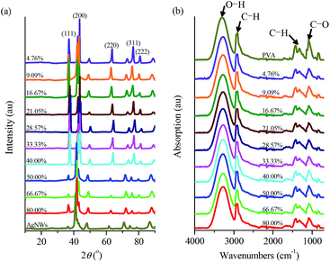
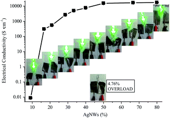
The prepared AgNWs featured diffraction angle (2θ) at 37.98, 43.94, 64.07, 77.61, and 81.58° on the WAXD patterns, corresponding to the characteristic diffraction peaks of (111), (200), (220), (311), and (222), respectively [Fig. 3(a)]. It is noted that the diffraction peak of (111) was much weaker than that of (200), maybe because the obtained AgNWs initially originated from nanocubes for nuclear, and the Ag ions grew along the (200) crystal face and finally had developed into cubic-shaped wires.32 Apparently, the AgNWs/PVA electrical compositor also displayed these same peaks as the AgNWs did [Fig. 3(a)]. In addition, the distinct peaks at the vicinity of 2θ = 20° belonging to PVA disappeared, might because the interactions between PVA with AgNWs [e.g., hydrogen bonds between PVA and residual polyvinylpyrrolidone (PVP) on AgNWs surfaces31] led to the decrease of the intermolecular interaction between the PVA chains and thus the crystalline degree.33 The PVA and AgNWs/PVA electrical compositor all presented similar, even exactly the same absorption peaks on the FTIR spectra [Fig. 3(b)], it was certain that there were no chemical reactions between PVA and AgNWs. The WAXD patterns [Fig. 3(a)] and FTIR spectra [Fig. 3(b)] both show that the AgNWs composited with PVA physically to form the AgNWs/PVA electrical compositor [Fig. 1(b)]; the former confirmed the highly crystal stability and the latter confirmed the highly chemical structure stability of the obtained AgNWs/PVA electrical compositors.To form highly conductive AgNWs/PVA electrical compositor, the AgNWs suspension solution was fixed at 40 g, the added PVA was 4, 2, 1, 0.75, 0.5, 0.4, 0.3, 0.2, 0.1, and 0.05 g, respectively, corresponding to the AgNWs contents at 4.76%, 9.09%, 16.67%, 21.05%, 28.57%, 33.33%, 40.00%, 50.00%, 66.67%, and 80.00% in AgNWs/PVA electrical compositors by the weight. The AgNWs/PVA electrical compositors were fabricated with the same size (80 mm × 80 mm) and different thicknesses at 47.30 (4.76%) to 23.40 (9.09%), 11.30 (16.67%), 7.50 (21.05%), 4.90 (28.57%), 4.39 (33.33%), 2.03 (40.00%), 1.99 (50.00%), 1.98 (66.67%), and 0.98 (80.00%) μm, that the thickness was basically determined by the added weight of PVA. And the excellent suspension properties of AgNWs ensured their uniform blending, dispersing, and compositing in AgNWs/PVA electrical compositors.29,30 Accordingly, the electrical conductivity of AgNWs/PVA electrical compositors increased evidently with the increasing AgNWs contents (Fig. 4). At the very low AgNWs contents, e.g., 4.76%, the AgNWs/PVA electrical compositor did not conduct, the electrical conductivity showed “OVERLOAD”. The quality of the electrically conductive properties is determined by the content of electrically conductive fillers.34,35 The electrically conductive networks, or called electrically conductive channels, are formed through the contact points and contact areas between/among the electrically conductive fillers, and the more the latter, the more the former. As Fig. 4 shows, the AgNWs/PVA electrical compositors were almost non-conductive at the very low AgNWs contents, such as 4.76% and 9.09%; the electrical conductivity was about several hundreds S cm−1 at the low AgNWs contents, about 310 and 550 S cm−1, respectively, at 16.67% and 21.05%. At the mediate AgNWs contents, e.g., 28.57%, 33.33%, and 40.00%, the electrical conductivity increased from 2670 to 5010 and 7660 S cm−1, and was about 15![[thin space (1/6-em)]](https://www.rsc.org/images/entities/char_2009.gif) 340, 16
340, 16![[thin space (1/6-em)]](https://www.rsc.org/images/entities/char_2009.gif) 690, and 17
690, and 17![[thin space (1/6-em)]](https://www.rsc.org/images/entities/char_2009.gif) 390 S cm−1 at the high AgNWs contents of 50.00%, 66.67%, and 80.00%. Obviously, the increasing electrical conductivity corresponded to the decrease of PVA and increase of AgNWs. When PVA contents were high, AgNWs as the fillers dispersed in the PVA matrix, they could not contact or touch each other, could not form electrically conductive networks. Vice versa, PVA as the fillers dispersed in the AgNWs matrix at high AgNWs contents. The AgNWs could form more electrically conductive networks, as the electrical conductivity reflected.
390 S cm−1 at the high AgNWs contents of 50.00%, 66.67%, and 80.00%. Obviously, the increasing electrical conductivity corresponded to the decrease of PVA and increase of AgNWs. When PVA contents were high, AgNWs as the fillers dispersed in the PVA matrix, they could not contact or touch each other, could not form electrically conductive networks. Vice versa, PVA as the fillers dispersed in the AgNWs matrix at high AgNWs contents. The AgNWs could form more electrically conductive networks, as the electrical conductivity reflected.
The embryos for the AgNWs “Chrysanthemum petal” arrangements were formed at 50.00% of the AgNWs content, the small, narrow AgNWs “Chrysanthemum petal” arrangements were formed at 66.67% of the AgNWs content, and the large, wide AgNWs “Chrysanthemum petal” arrangements were formed at 80.00% of the AgNWs content [Fig. 1(c), (d), (f), and (g)].31 The AgNWs/PVA electrical compositors had given high electrical conductivity, e.g., 15![[thin space (1/6-em)]](https://www.rsc.org/images/entities/char_2009.gif) 340, 16
340, 16![[thin space (1/6-em)]](https://www.rsc.org/images/entities/char_2009.gif) 690, and 17
690, and 17![[thin space (1/6-em)]](https://www.rsc.org/images/entities/char_2009.gif) 390 S cm−1 at these three contents, much higher than those results in the existed reports,24,25,36 also with very low sheet resistance, about 0.30, 0.31, and 0.34 Ω sq−1. The formed bunches made up of the AgNWs/PVA electrical compositors at these three contents. They stacked together and increased the electrically conductive networks and electrically conductive areas. Especially at 80.00% of the AgNWs content, the AgNWs/PVA electrical compositor was dominantly consisted of the perfect AgNWs “Chrysanthemum petal” arrangements, resulting from hundreds or thousands of wires. PVA was dissolved in the fabrication of AgNWs/PVA [Fig. 1(a)]. Its molecular chains and/or molecular segments adhered and attached onto the AgNWs surfaces physically; they then connected the AgNWs in series, similar to the series connection for pearl necklaces or other nano layers.37,38 In addition, PVA was connected onto the AgNWs surfaces by forming hydrogen bonds,39,40 and those PVA and PVP on the surfaces of different AgNWs also formed hydrogen bonds and let the AgNWs undergo self-assemblies and align directionally.37,41 Besides, the heat transferring and water evaporating during the solidification changed the micro and nano kinetics, let the PVA chains and water molecules move fast and frequently, as stated by Collision theory42 or Brownian movement,43 further increased the collides, contacts, and touches between/among the AgNWs. The solidified AgNWs/PVA often showed shrinking volumes, that these shrinkages on the volumes increased the probability and opportunity of collides, contacts, and touches for AgNWs.34,35 And the evaporation kinetics for water caused the stretching and shrinking in micro or nano scale, like capillary action,44 made the AgNWs arrange or align directionally. With micro scale, the formed AgNWs “Chrysanthemum petal” arrangements played a similar role, like the silver micro flakes, in the electrical compositors and electrically conductive adhesives,34,35 and formed many electrically conductive networks and large electrically conductive areas, which had already given contributions to the increase of electrical conductivity.
390 S cm−1 at these three contents, much higher than those results in the existed reports,24,25,36 also with very low sheet resistance, about 0.30, 0.31, and 0.34 Ω sq−1. The formed bunches made up of the AgNWs/PVA electrical compositors at these three contents. They stacked together and increased the electrically conductive networks and electrically conductive areas. Especially at 80.00% of the AgNWs content, the AgNWs/PVA electrical compositor was dominantly consisted of the perfect AgNWs “Chrysanthemum petal” arrangements, resulting from hundreds or thousands of wires. PVA was dissolved in the fabrication of AgNWs/PVA [Fig. 1(a)]. Its molecular chains and/or molecular segments adhered and attached onto the AgNWs surfaces physically; they then connected the AgNWs in series, similar to the series connection for pearl necklaces or other nano layers.37,38 In addition, PVA was connected onto the AgNWs surfaces by forming hydrogen bonds,39,40 and those PVA and PVP on the surfaces of different AgNWs also formed hydrogen bonds and let the AgNWs undergo self-assemblies and align directionally.37,41 Besides, the heat transferring and water evaporating during the solidification changed the micro and nano kinetics, let the PVA chains and water molecules move fast and frequently, as stated by Collision theory42 or Brownian movement,43 further increased the collides, contacts, and touches between/among the AgNWs. The solidified AgNWs/PVA often showed shrinking volumes, that these shrinkages on the volumes increased the probability and opportunity of collides, contacts, and touches for AgNWs.34,35 And the evaporation kinetics for water caused the stretching and shrinking in micro or nano scale, like capillary action,44 made the AgNWs arrange or align directionally. With micro scale, the formed AgNWs “Chrysanthemum petal” arrangements played a similar role, like the silver micro flakes, in the electrical compositors and electrically conductive adhesives,34,35 and formed many electrically conductive networks and large electrically conductive areas, which had already given contributions to the increase of electrical conductivity.
Mechanical properties
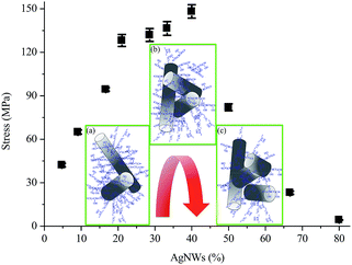
Fig. 5 shows the breaking stress of AgNWs/PVA electrical compositors vs. AgNWs contents at 4.76%, 9.09%, 16.67%, 21.05%, 28.57%, 33.33%, 40.00%, 50.00%, 66.67%, and 80.00% by the weight. It can be seen that with the increasing AgNWs content the stress firstly increased, and reached the maximum value at the AgNWs content at 40.00%, hereafter decreased, resulted from the further continuingly incorporated AgNWs. In this study, the diameter was about 60 nm and the length was more than 60 μm, even at 120–130 μm for the AgNWs [Fig. 2(b)], the aspect ratio was more than 1000, based on which the AgNWs provided crosslinking points or anchoring points for PVA macromolecules and played reinforcing roles in the AgNWs/PVA electrical compositors. And the more the AgNWs, the more the crosslinking points or anchoring points would be produced, as the insert (a) shows in Fig. 5. So the stress increased from 42.20 to 148.21 MPa as the AgNWs content changed from 4.76% to 40.00%.The maximum stress of 148.21 MPa was obtained at the AgNWs content of 40.00%, at which there were enough PVA macromolecules to provide the strength and enough AgNWs to provide the crosslinking points or anchoring points, as the insert (b) shows in Fig. 5. Combined them together, the AgNWs/PVA electrical compositors displayed the highest strength at this point. However, exceeding or after the AgNWs content of 40.00%, the continuously increasing AgNWs content led to too many crosslinking points or anchoring points in the AgNWs/PVA electrical compositors, which had cut off the connections between/among PVA macromolecules, decreased the contacts between/among them, and increased the solid-to-solid contacts between/among AgNWs, as the insert (c) shows in Fig. 5. Therefore, the stress decreased accordingly, e.g., from 148.21 to 4.33 MPa as the AgNWs changed from 40.00% to 80.00%.
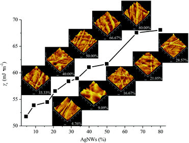
Definitely, the AgNWs also significantly influenced the surface properties of AgNWs/PVA electrical compositors. With the decrease of PVA and the increase of AgNWs, the surface roughness of AgNWs/PVA electrical compositors also changed correspondingly, as the profile arithmetic average error (Ra) and profile maximum height (Rz) show in Fig. 6. The surface roughness increased with the increasing AgNWs contents, e.g., the Ra changed from 2.78 to 19.76 nm and the Rz changed from 21.8 to 144.8 nm as the AgNWs content increased from 4.76% to 80.00%. With the decreasing PVA content, AgNWs appeared or were exposed on the surface of AgNWs/PVA electrical compositors more by more, in the form of wires and bunches, that increased the surface roughness, as the inserted 3D models show in Fig. 7. The surface free energy (γS) of AgNWs/PVA electrical compositors was calculated using the Owens–Wendt geometric mean equation:
| γS = γdS + γpS |
where γS is the surface free energy of solids, γdS is the dispersive forces of solids, γpS is the polar forces of solids, γL is the surface free energy of liquids, γdL is the dispersive forces of liquids, γpL is the polar forces of liquids, and α is the contact angle. In this study, the deionized water and DCM were used for the tested liquids. The γL, γdL, and are 72.8, 21.8, and 51.0 mJ m−2 for deionized water, and 28.6, 26.5, and 2.1 mJ m−2 for DCM, respectively.37,38
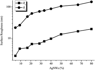 | ||
| Fig. 6 Surface roughness (Ra and Rz) of AgNWs/PVA electrical compositors vs. AgNWs contents at 4.76%, 9.09%, 16.67%, 21.05%, 28.57%, 33.33%, 40.00%, 50.00%, 66.67%, and 80.00% by the weight. | ||
The γS had a close relationship to the surface roughness and the AgNWs content. As Table 1 shows, the contact angles decreased (e.g., from 46.76 to 24.14° obtained from deionized water and 8.35 to 2.10° obtained from DCM as the AgNWs content changed from 4.76% to 80.00%) and the γdS decreased as well (e.g., from 14.50 to 11.86 mJ m−2 as the AgNWs content changed from 4.76% to 80.00%).
| AgNWs/PVA electrical compositor | ||||||||||
|---|---|---|---|---|---|---|---|---|---|---|
| AgNWs (%) | 4.76 | 9.09 | 16.67 | 21.05 | 28.57 | 33.33 | 40.00 | 50.00 | 66.67 | 80.00 |
| Water (°) | 46.70 | 44.05 | 43.27 | 40.64 | 38.25 | 37.54 | 34.72 | 33.86 | 25.02 | 24.14 |
| DCM (°) | 8.35 | 6.77 | 5.11 | 4.85 | 4.65 | 4.38 | 4.28 | 3.86 | 2.67 | 2.10 |
| γdS (mJ m−2) | 14.50 | 14.16 | 14.11 | 13.72 | 13.38 | 13.29 | 12.93 | 12.83 | 11.92 | 11.86 |
| γpS (mJ m−2) | 37.24 | 39.69 | 40.35 | 42.81 | 45.00 | 45.63 | 48.10 | 48.82 | 55.62 | 56.20 |
| γS (mJ m−2) | 51.74 | 53.85 | 54.46 | 56.53 | 58.38 | 58.92 | 61.03 | 61.66 | 67.55 | 68.06 |
While the γpS and γS both increased, e.g., from 37.24 to 56.20 mJ m−2 and from 51.74 to 68.06 mJ m−2, respectively, as the AgNWs content changed from 4.76% to 80.00%. For the hydrophilic materials, high surface roughness always means high hydrophilicity. In this study, the used PVA is a hydrophilic polymer. So the increasing AgNWs content raised the surface roughness (Fig. 6 and 7), consequently reduced the contact angles and the γdS (Table 1), and improved the γpS and γS (Table 1 and Fig. 7), from which the fabricated AgNWs/PVA electrical compositors in this study had high surface hydrophilicity and high surface wettability. This can let the AgNWs/PVA electrical compositors be facilely used in hydrophobic occasions and those occasions difficult to bond, seal, or package, and also indirectly ensure the good biological properties and biocompatibility of them.
Thermal stability
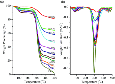
The thermal stability of AgNWs/PVA electrical compositors was reflected from their thermal degradations. Fig. 8 shows the TGA traces of AgNWs/PVA electrical compositors vs. AgNWs contents at 4.76%, 9.09%, 16.67%, 21.05%, 28.57%, 33.33%, 40.00%, 50.00%, 66.67%, and 80.00% by the weight. It can be seen that the thermal degradations of the pure PVA and all the AgNWs/PVA electrical compositors started at about 250 °C, presented a sharp weight loss around 310 °C, and ended at about 400 °C; and according to the elementary knowledge, when PVA completely degraded at 500 °C, AgNWs would be still very stable, so it was certain that the char yield up to 500 °C was approximately equal to their respective AgNWs content in AgNWs/PVA electrical compositors [Fig. 8(a)]. The maximum weight loss rate was 0.6443% s−1 for pure PVA, and 0.3802, 0.3685, 0.3650, 0.3437, 0.3231, 0.3060, 0.1501, 0.1337, 0.1207, and 0.0506% s−1 for AgNWs/PVA electrical compositors corresponding to the AgNWs content at 4.76%, 9.09%, 16.67%, 21.05%, 28.57%, 33.33%, 40.00%, 50.00%, 66.67%, and 80.00% by the weight [Fig. 8(b)], because the more the AgNWs in the AgNWs/PVA electrical compositors, the less the PVA macromolecules were pyrolysized in a unit time.Besides the above described electrical properties, mechanical properties, and thermal stability, the method reported in this study had displayed other several apparent advantages compared to those already reported methods of using PVA and AgNWs to fabricate conductors.45,46 Firstly, the diameter was about 60 nm and the length was more than 60 μm for the AgNWs [Fig. 2(b)], the aspect ratio was more than 1000, much larger than that at about 100 used by Zeng et al.45 and Romeo et al.,46 which had ensured the high conductivity of AgNWs/PVA electrical compositors fabricated in this study. Secondly, Zeng et al. used a burying method to fabricate the transparent conductor, that a uniform AgNW network was deposited on a poly(ethylene terephthalate) (PET) substrate by vacuum filtration and transfer, then an aqueous solution of PVA was cast or spin coated over the AgNW network, and after drying at 80 °C for 1 h and 100 °C for 1 h, the dried PVA matrix together with all AgNWs was peeled off the PET surface, a solid and smooth conductive surface was obtained by burying the AgNW film at the surface of the PVA matrix.43 While Romeo et al. used an ice segregation induced self-assembly (ISISA) method to fabricate the electrically conductive macroporous scaffolds, that the liquid crystalline AgNWs were dispersed in PVA aqueous solutions, then the prepared PVA/AgNWs dispersions were poured into insulin syringes and dipped at a constant advancing ice front rate into a cold bath maintained at 77 K and under room pressure, the unidirectionally frozen samples were freeze dried for 48 h, the obtained monoliths kept both their size and shape, and the highly ordered macroporous PVA scaffolds containing self-organized AgNWs embedded in their walls were produced.44 Apparently differing from them, we used a simple one-step blending method to fabricate the AgNWs/PVA electrical compositors, as shown in Fig. 1(a). Thirdly, the AgNWs/PVA electrodes presented the sheet resistance at 63 Ω (3 mm × 30 mm)45 and the AgNWs/PVA electrically conductive macroporous scaffolds presented the electrical conductivity at 1.4 × 10⁻⁴ to 1.7 × 10⁻⁴ S cm−1,46 that the results of AgNWs/PVA electrical compositors obtained in this study were much better than them, e.g., 15![[thin space (1/6-em)]](https://www.rsc.org/images/entities/char_2009.gif) 340, 16
340, 16![[thin space (1/6-em)]](https://www.rsc.org/images/entities/char_2009.gif) 690, and 17
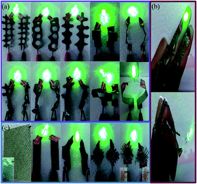
690, and 17![[thin space (1/6-em)]](https://www.rsc.org/images/entities/char_2009.gif) 390 S cm−1 at the 50.00%, 66.67%, and 80.00% of the AgNWs content, the corresponding low sheet resistance was at about 0.30, 0.31, and 0.34 Ω sq−1. Finally, the fabricated AgNWs/PVA electrodes was just used to replace the indium tin oxide (ITO),45 while the AgNWs/PVA electrical compositors obtained in this study had wide applications because of their super flexibility. As Fig. 9(a) shows, the AgNWs/PVA electrical compositor was made into various shapes, e.g., ladder shape, chain shape, fence shape, curved shape, even being twisted as possible, all displayed highly, stably electrical conductivity.
390 S cm−1 at the 50.00%, 66.67%, and 80.00% of the AgNWs content, the corresponding low sheet resistance was at about 0.30, 0.31, and 0.34 Ω sq−1. Finally, the fabricated AgNWs/PVA electrodes was just used to replace the indium tin oxide (ITO),45 while the AgNWs/PVA electrical compositors obtained in this study had wide applications because of their super flexibility. As Fig. 9(a) shows, the AgNWs/PVA electrical compositor was made into various shapes, e.g., ladder shape, chain shape, fence shape, curved shape, even being twisted as possible, all displayed highly, stably electrical conductivity.
Then the AgNWs/PVA electrical compositor was further adhered onto fingers, like electronic skins, whether stretching, shrinking, or bending the joints, they also showed highly, stably electrical conductivity, as shown in Fig. 9(b). Moreover, the AgNWs/PVA suspension solution was printed onto textiles, as Fig. 9(c) shows. The AgNWs and PVA wrapped the microfibers uniformly, forming the smart textiles; even being verily twisted, or in the form of woven structures with large meshes, all presented highly, stably electrical conductivity. In a word, the AgNWs/PVA electrical compositors can be made into various shapes, can be used on any substrate and any curved surface, can be used as smart textiles and electronic skins, which will well facilitate the development of flexible electronics, especially in those fields associated with biology, medicine, food, and life.
Conclusions
In this study, PVA and AgNWs have been mixed together with a simple one-step blending method to form hybrid electrical compositor. Super flexible and highly conductive electrical compositors were successfully developed with the AgNWs content of 80%, in which hundreds, even thousands of AgNWs stacked into order “Chrysanthemum petal” to exhibit high electrical conductivity of 17![[thin space (1/6-em)]](https://www.rsc.org/images/entities/char_2009.gif) 390 S cm−1. The high conductivity was corresponded to the formation of a large amount of electrically conductive networks and channels. The conductively electrical compositor can be made into various shapes and can be used on any substrate with different curved surface because the compositor ink is so stability and can be stored for a long time without other additives. The compositor is expected to have a great potential application in the flexible electronics, especially in those fields associated with biology, medicine, food, and life.
390 S cm−1. The high conductivity was corresponded to the formation of a large amount of electrically conductive networks and channels. The conductively electrical compositor can be made into various shapes and can be used on any substrate with different curved surface because the compositor ink is so stability and can be stored for a long time without other additives. The compositor is expected to have a great potential application in the flexible electronics, especially in those fields associated with biology, medicine, food, and life.
Notes and references
- T. Sekitani, H. Nakajima, H. Maeda, T. Fukushima, T. Aida, K. Hata and T. Someya, Nat. Mater., 2009, 8, 494–499 CrossRef CAS PubMed.
- T. Sekitani, U. Zschieschang, H. Klauk and T. Someya, Nat. Mater., 2010, 9, 1015–1022 CrossRef CAS PubMed.
- M. Kubo, X. F. Li, C. Kim, M. Hashimoto, B. J. Wiley, D. Ham and G. M. Whitesides, Adv. Mater., 2010, 22, 2749–2752 CrossRef CAS PubMed.
- S. Beer, H. Gulan, C. Rusch and T. Zwick, IEEE Trans. Antennas Propag., 2013, 61, 1564–1572 CrossRef.
- M. Zhang, S. L. Fang, A. A. Zakhidov, S. B. Lee, A. E. Aliev, C. D. Williams, K. R. Atkinson and R. H. Baughman, Science, 2005, 309, 1215–1219 CrossRef CAS PubMed.
- A. E. Aliev, J. Y. Oh, M. E. Kozlov, A. A. Kuznetsov, S. L. Fang, A. F. Fonseca, R. Ovalle, M. D. Lima, M. H. Haque, Y. N. Gartstein, M. Zhang, A. A. Zakhidov and R. H. Baughman, Science, 2009, 323, 1575–1578 CrossRef CAS PubMed.
- J. A. Rogers, T. Someya and Y. G. Huang, Science, 2010, 327, 1603–1607 CrossRef CAS PubMed.
- J. A. Rogers, Science, 2013, 341, 968–969 CrossRef CAS PubMed.
- H. M. Lee, S. Y. Choi, A. Jung and S. H. Ko, Angew. Chem., Int. Ed., 2013, 52, 7718–7723 CrossRef CAS PubMed.
- J. Yeo, G. Kim, S. Hong, M. S. Kim, D. Kim, J. Lee, H. B. Lee, J. Kwon, Y. D. Suh, H. W. Kang, H. J. Sung, J. H. Choi, W. H. Hong, J. M. Ko, S. H. Lee, S. H. Choa and S. H. Ko, J. Power Sources, 2014, 246, 562–568 CrossRef CAS PubMed.
- C. Y. Lim and K. Kim, J. Elec. Eng. Technol., 2014, 9, 372–377 CrossRef.
- W. Ding, J. Liu and Y. P. Li, J. Comput. Theor. Nanosci., 2014, 11, 444–449 CrossRef CAS PubMed.
- N. Bowden, S. Brittain, A. G. Evans, J. W. Hutchinson and G. M. Whitesides, Nature, 1998, 393, 146–149 CrossRef CAS PubMed.
- D. S. Gray, J. Tien and C. S. Chen, Adv. Mater., 2004, 16, 393–397 CrossRef CAS.
- T. Someya, T. Sekitani, S. Iba, Y. Kato, H. Kawaguchi and T. A. Sakurai, Proc. Natl. Acad. Sci. U. S. A., 2004, 101, 9966–9970 CrossRef CAS PubMed.
- T. Someya, Y. Kato, T. Sekitani, S. Iba, Y. Noguchi, Y. Murase, H. Kawaguchi and T. Sakurai, Proc. Natl. Acad. Sci. U. S. A., 2005, 102, 12321–12325 CrossRef CAS PubMed.
- T. X. Cui, R. T. Lv, Z. H. Huang, X. Gan, K. L. Wang, D. H. Wu, H. W. Zhu and F. Y. Kang, RSC Adv., 2013, 3, 22295–22300 RSC.
- B. Li, X. T. Zhang, P. Chen, X. H. Li, L. L. Wang, C. Zhang, W. T. Zheng and Y. C. Liu, RSC Adv., 2014, 4, 2404–2408 RSC.
- F. Xu, X. Wang, Y. T. Zhu and Y. Zhu, Adv. Funct. Mater., 2012, 22, 1279–1283 CrossRef CAS.
- J. W. Han, B. Kim, J. Li and M. Meyyappan, RSC Adv., 2014, 4, 549–553 RSC.
- L. B. Hu, H. S. Kim, J. Y. Lee, P. Peumans and Y. Cui, ACS Nano, 2010, 4, 2955–2963 CrossRef CAS PubMed.
- V. Scardaci, R. Coull, P. E. Lyons, D. Rickard and J. N. Coleman, Small, 2011, 7, 2621–2628 CrossRef CAS PubMed.
- J. Jiu, T. Araki, J. Wang, M. Nogi, T. Sugahara, S. Nagao, H. Koga, K. Suganuma, E. Nakazawa, M. Hara, H. Uchida and K. Shinozaki, J. Mater. Chem. A, 2014, 2, 6326–6330 CAS.
- F. Xu and Y. Zhu, Adv. Mater., 2012, 24, 5117–5122 CrossRef CAS PubMed.
- J. Ge, H. B. Yao, X. Wang, Y. D. Ye, J. L. Wang, Z. Y. Wu, J. W. Liu, F. J. Fan, H. L. Gao, C. L. Zhang and S. H. Yu, Angew. Chem., Int. Ed., 2013, 52, 1654–1659 CrossRef CAS PubMed.
- C. Yan, J. Wang, X. Wang, W. Kang, M. Cui, C. Y. Foo and P. S. Lee, Adv. Mater., 2014, 26, 943–950 CrossRef CAS PubMed.
- M. S. Abdel-Aziz and A. M. Hezma, Polym.-Plast. Technol. Eng., 2013, 52, 1503–1509 CrossRef CAS.
- B. Gupta, S. Anjum and S. Ikram, Polym. Bull., 2013, 70, 2709–2725 CrossRef CAS.
- T. Tokuno, M. Nogi, M. Karakawa, J. T. Jiu, T. T. Nge, Y. Aso and K. Suganuma, Nano Res., 2011, 4, 1215–1222 CrossRef CAS.
- J. T. Jiu, M. Nogi, T. Sugahara, T. Tokuno, T. Araki, N. Komoda, K. Suganuma, H. Uchida and K. Shinozaki, J. Mater. Chem., 2012, 22, 23561–23567 RSC.
- H. W. Cui, J. T. Jiu, T. Sugahara, S. Nagao, K. Suganuma and H. Uchida, Nanotechnology, 2014, 25, 485705 CrossRef PubMed.
- A. R. Siekkinen, J. M. McLellan, J. Chen and Y. Xia, Chem. Phys. Lett., 2006, 432, 491–496 CrossRef CAS PubMed.
- Y. A. Badr, K. M. Abd El-Kader and R. M. Khafagy, J. Appl. Polym. Sci., 2004, 92, 1984–1992 CrossRef CAS.
- H. W. Cui, Q. Fan and D. S. Li, Polym. Int., 2013, 62, 1644–1651 CAS.
- H. W. Cui, J. T. Jiu, S. Nagao, T. Sugahara, K. Suganuma, H. Uchida and K. A. Schroder, RSC Adv., 2014, 4, 15914–15922 RSC.
- Y. Kim, J. Zhu, B. Yeom, M. Di Prima, X. L. Su, J. G. Kim, S. J. Yoo, C. Uher and N. A. Kotov, Nature, 2013, 500, 59–63 CrossRef CAS PubMed.
- H. W. Cui and S. W. Kuo, J. Polym. Res., 2013, 20, 114 CrossRef PubMed.
- H. W. Cui and S. W. Kuo, Appl. Clay Sci., 2014, 91–92, 1–5 CrossRef CAS PubMed.
- Z. Q. Wang, Y. M. Zhou and Y. Q. Sun, Polym. Bull., 2009, 63, 699–708 CrossRef CAS PubMed.
- H. W. Cui, W. C. Chu, J. K. Chen and S. W. Kuo, Eur. Polym. J., 2014, 50, 168–176 CrossRef CAS PubMed.
- H. W. Cui and G. B. Du, Adv. Polym. Technol., 2013, 32, 21343 CrossRef.
- S. A. Safron, N. D. Weinstein, D. R. Herschbach and J. C. Tully, Chem. Phys. Lett., 2013, 589, 7–8 CrossRef CAS PubMed.
- C. Y. Zenkova, M. P. Gorsky, I. V. Soltys and P. O. Angelsky, Opto-Electron. Rev., 2012, 20, 247–254 CrossRef CAS PubMed.
- O. J. Lieberman, M. W. Orr, Y. Wang and V. T. Lee, ACS Chem. Biol., 2014, 9, 183–192 CrossRef CAS PubMed.
- X. Y. Zeng, Q. K. Zhang, R. M. Yu and C. Z. Lu, Adv. Mater., 2010, 22, 4484–4488 CrossRef CAS PubMed.
- H. E. Romeo, C. E. Hoppe, M. A. Lopez-Quintela, R. J. J. Williams, Y. Minaberry and M. Jobbagy, J. Mater. Chem., 2012, 22, 9195–9201 RSC.
| This journal is © The Royal Society of Chemistry 2015 |

