
 Open Access Article
 This Open Access Article is licensed under a
 Creative Commons Attribution 3.0 Unported Licence
Atomic layer deposition of Al2O3 process emissions†
Lulu
Ma
,
Dongqing
Pan
,
Yuanyuan
Xie
and
Chris
Yuan
*
Department of Mechanical Engineering, University of Wisconsin Milwaukee, Milwaukee 53211, USA. E-mail: Cyuan@uwm.edu; Tel: +1-414-229-5639
First published on 13th January 2015
Abstract
The ALD process emissions and the associated chemical reaction mechanism in the ALD of the Al2O3 system are studied and reported. In gaseous emissions, 3.22 vol% of CH4 and 6.01 × 10⁻² vol% of C2H6 are found. Net peak emissions of aerosols are found between 1 × 10³ and 1 × 10⁴ # cm−3 and net total emissions of 25 cycles are in the range of 6.0 × 10⁵ and 2.5 × 10⁶ particles. Most aerosols are determined as ultrafine particles with diameter smaller than 100 nm. Purging time has significant impacts on emission concentrations but no effect on size distribution. Both main and side chemical reactions are observed in the ALD system. X-ray photoelectron spectroscopy (XPS) shows that besides O–Al which represents the existence of Al2O3, a significant amount of C-containing by-products are also generated. Chemical bonds observed in C-containing products are C–H, C–O and C![[double bond, length as m-dash]](https://www.rsc.org/images/entities/char_e001.gif) O. The main reactions can be considered stable to a certain extent, while side reactions accelerate along internal tubes and finally exceed the speed of the main reactions near the outlet of the ALD system. These results could help us to understand the potential environmental impacts of ALD nanotechnology and guide the technology's sustainable scale-up in the future.
O. The main reactions can be considered stable to a certain extent, while side reactions accelerate along internal tubes and finally exceed the speed of the main reactions near the outlet of the ALD system. These results could help us to understand the potential environmental impacts of ALD nanotechnology and guide the technology's sustainable scale-up in the future.
Introduction
In recent years, atomic layer deposition (ALD) has found a broad array of industrial applications including semiconductors,1,2 solar cells,3,4 polymers,5,6 and catalysts.7 In nature, ALD operates by alternating exposure of a substrate to two or more precursors in a cyclic manner. Advantages of ALD include: (1) thickness of ALD film can be controlled at the atomic scale; (2) deposition can be achieved on complex surfaces; (3) uniform, conformal and pinhole-free nano-scale thin films can be fabricated. ALD technology can be used to deposit a wide variety of materials. Usually ALD of Al2O3 is studied as the model process of ALD technology. In this process, Al2O3 thin film is usually obtained through a binary reaction of H2O and trimethylaluminum (TMA) with a typical growth rate of 1 Å per cycle.8 The overall reaction in ALD of Al2O3 can be described as:| 2Al(CH3)3 + 3H2O → Al2O3 + 6CH4, ΔH = −376 kcal |
ALD is a self-limited process and only a small portion of the precursors loaded into ALD chamber is deposited on the substrate, while a large portion is discarded as wastes and emissions.9 Past ALD research was focused on ALD technology development. There are few researches on ALD process emissions and its relevant environmental impacts. As per the reaction mechanism in ALD process, theoretical emissions are TMA, Al2O3, CH4 and some intermediate reactants. Once released into atmosphere, they can generate certain environmental impacts and also pose potential risks of exposure to both occupational and public health. For instance, CH4 is a flammable and a major greenhouse gas.10 Global warming potential of CH4 is 25 times higher than that of CO2, so it has a much larger greenhouse effect.11 Intake of Al2O3 through human exposure could cause a series of neuro-toxicity diseases, including reduction of memory, impairment of psychomotor reaction and disorder of emotional balance.12 As a nano-manufacturing process, ALD of Al2O3 also produces significant amount of aerosol emissions. Aerosols with higher concentrations can cause adverse effects on human health. It is well known that particles smaller than 10 μm are able to penetrate alveolar region of lung. Ultrafine particles, smaller than 100 nm, can penetrate membranes of respiratory system, enter blood and finally arrive in brain through circulatory system.12,13 While the ALD of Al2O3 process emissions are of grave concerns because of their potential adverse effects on the environment and human health, however, there is no scientific study so far conducting on the process emissions and the behind mechanism from ALD nano-manufacturing process. This paper is to report our experimental results on the ALD process emissions and the findings on the associated chemical reaction mechanism. The results may facilitate understanding of the potential environmental impacts of the ALD nanotechnology and guide its sustainable scale-up for future large-scale industrial applications.
Experimental methods
Instrumental setup and sample collection
Fig. 1 is a schematic of the ALD system (Savannash 100, Cambridge Nano Tech Inc.). Two precursors: H2O (ultrapure grade) and trimethylaluminum (TMA, Strem Chemicals Inc.) were exposed into the reaction chamber alternatively, as controlled by two individual diaphragm ALD valves (Swagelok). ALD reactions are performed in cycles. One cycle of ALD reaction has four basic steps: (1) pulse H2O into reaction chamber; (2) purge the chamber to remove extra H2O; (3) pulse TMA into reaction chamber; (4) purge the chamber to remove extra TMA. TMA is an extremely flammable chemical and will ignite spontaneously when come in contact with air. Therefore, exposure of TMA in air must be avoided.14 In our experimental tests, exposure time of both H2O and TMA was fixed at 0.015 s and purging time was set in the range between 4 and 20 s. 20 sccm of N2 was used as carrier gas to flow through the system constantly. A stop valve was installed below the reaction chamber to help control gas flow. Stop valve and ALD valves were operated by compressed air. An inner disk heater embedded in the reaction chamber and heating jackets for other components were used to provide appropriate temperature to the system. In this study, temperature inside the reaction chamber was set at 200 °C. ALD valves and exhaust system including stop valve and pipeline were heated to 150 °C. Neither TMA nor H2O needed to be heated; so cylinders of two precursors were placed in room temperature. A vacuum pump (XDS 10, Edwards Vacuum, Inc.) was installed at the end of the exhaust pipeline to provide a low pressure (about 0.4 Torr) to the whole system and pump out the extra precursors from the chamber.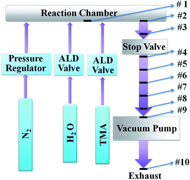 | ||
| Fig. 1 Schematic of Al2O3 ALD system (Savannash 100, Cambridge Nano Tech Inc.). | ||
The ALD process emissions and the emission generation mechanism are systematically investigated along the exhaust pipeline of the ALD system. 10 pieces of Si wafers are prepared as sample holders to collect chemical resultants within the ALD exhaust pipeline. Their locations are labeled in the schematic of instrumental setup in Fig. 1. Sample 1 locates in the center of the reaction chamber. Sample 2 and 3 are placed in the exhaust pipeline above the stop valve, and sample 4–9 are placed below the stop valve. Sample 10 is placed at the pump outlet under ambient temperature. Purging time between two pulses was set at 8 s. In this study, these silicon samples are exposed to the same ALD process reactions. In order to improve the efficiency of particle collection, particles emitted from vacuum pump are also collected on a piece of TEM grid (TED PELLA, INC., Prod no. 01824) by aerosols sampler (TSI 3089), where charged particles deposited on a piece of conductive grid through electric field.
Emission analysis
Aerosols emitted from ALD reaction were measured directly at outlet of pump without pre-treatment. Concentration of aerosols was measured by ultrafine condensation particle counter (UCPC, TSI 3776). Size distribution was obtained using a scanning mobility particle sizer (SMPS, TSI 3936) which consists of an electrostatic classifier (TSI 3080) and UCPC. Detailed instrument setup is described in ESI.† In this experiment, five different purging times were used at 4 s, 8 s, 12 s, 16 s and 20 s to study their effects on the ALD process emissions.Gas emissions were collected at the outlet of pump by a sealed Swagelok gas cylinder and analyzed in the ORS lab (Oneida Research Services Inc.). Purging time between pulses was set at 8 s, the same as Si wafer analysis.
Analysis of chemicals deposited on Si wafer
Because Si wafer was not transparent, reflection method was selected for UV-Vis spectroscopy measurement (light source: DT 1000CE, Analytical Instrument Systems, Inc.; detector: SD2000, Ocean Optics, Inc.). A piece of clean Si wafer was used as background and its reflection was set at 100%.X-ray photoelectron spectroscopy (XPS, HP 5950A ESCA Spectrometer) was used to determine functional groups of depositions. Concentration of each element was provided by energy-dispersive X-ray spectroscopy (EDS, QUANTAX EDS, Bruker Corp.).
Results and discussion
Gaseous emissions
Analysis of the gaseous emissions shows the existence of N2, CH4, H2O and C2H6. Concentration of each component is listed in Table 1.| Component | Concentration in ALD emission (vol%) |
|---|---|
| N2 | 94.98 |
| CH4 | 3.10 |
| H2O | 1.86 |
| C2H6 | 6.01 × 10⁻² |
N2 has the highest concentration at 94.98 vol% because it is used as carrier gas to flow through the system consistently. The ALD system is airtight. Though compressed air is used to operate stop valve and ALD valves, it is not introduced into the system. Both N2 and compressed air are in dry grade, so 1.86 vol% of H2O is from extra H2O precursor only. CH4, the theoretical gaseous resultant, has concentration of 3.10 vol%, which is close to the lower flammability limit of CH4 at 5 vol%.15 6.01 × 10⁻² vol% of C2H6 is also found in the gaseous emission. In the ALD reaction of TMA and H2O, a small amount of Al–Al is commonly observed in XPS data. This peak is ably reduced by replacing H2O with O3.16 Methyl radicals CH3˙ can be generated by reacting TMA with Al.17 They are highly reactive and form C2H6 easily.
Aerosol emissions
Aerosols emissions from the ALD of Al2O3 reactions, including net peak emission and net total emissions of 25 cycles, are shown in Fig. 2. | ||
| Fig. 2 Net peak emissions of aerosols and net total emission of 25 cycles of ALD reaction measured at pump outlet. | ||
Net peak emission of aerosols is in the range of 8.0 × 10³ and 2.6 × 10⁴ # cm−3. The emission decreases with the increase of purging time. Average global aerosol concentration at continental boundary layer was detected in the range of 1 × 10³ to 1 × 10⁴ # cm−3.18 So concentration of aerosols emitted by ALD reaction is 3 to 10 times larger than the average concentration of global aerosols, and thus is a significant source of air pollution. Concentration of net total emissions is in the range of 6.0 × 10⁵ and 2.5 × 10⁶ particles. Net total emissions also decrease with the increase of purging time. Since pulsing time of each precursor is fixed at 0.015 s, the amounts of precursors injected into the reaction chamber per cycle are the same. The drop of total emission at large purging time indicates that more precursors are adsorbed in the ALD pipeline. Once deposited by precipitation, the surface of pipeline will have a larger tendency of further deposition.19 These precipitations accumulated along ALD pipeline will lower the heat transfer, prevent gas flow and decrease energy efficiency.19,20
Though purging time shows a great influence on the number concentration of aerosol emission, it has limited effect on size distribution, as shown in Fig. 3. Size distribution of aerosols locates in the range between 10 and 300 nm regardless of purging times varying from 4 to 20 s. Most aerosols are ultrafine particles smaller than 100 nm.
 | ||
| Fig. 3 (A), (B), (C), (D) and (E) are results of size distribution of aerosols emitted at 5 different purging times: 20, 16, 12, 8 and 4 s, respectively. | ||
UV-Vis analysis of chemicals deposited on Si wafer
To identify the side reactions in the ALD system and identify the emission mechanism from ALD of Al2O3 process, components and chemical properties of ALD emissions and the samples installed along internal pipeline are investigated using UV-Vis reflection spectra, XPS and EDS.Fig. 4 is the UV-Vis reflection spectra of the 10 samples between 300 and 1000 nm. A piece of clean Si wafer is used as background and its reflection is set at 100%. By defining clean Si piece having the first type of UV-Vis spectrum (A), the spectra of the 10 samples can be divided into 3 types: (B), (C) and (D). Type (B), having the smallest reflection at about 350 nm, is observed on sample 1, 2, 4, 5 and 6. Type (C), showing smallest reflection at about 450 nm, is found on sample 3, 8 and 9. (D) is the result of sample #10 collected on the outlet of pump. The optical bandgap of ALD Al2O3 film is determined at 6.4 ± 0.1 eV, so it is transparent above 200 nm.21,22 However, all of the samples in Fig. 4 show significant reflection drop, indicating that chemicals other than Al2O3 have been generated and emitted into atmosphere. Reflection curves of sample 1, 2, 4, 5, and 6 decrease gradually from sample 1 to 2 and 4 to 6, respectively with similar spectrum shape. Continuous reflection drop indicates increase of film thickness on Si wafer. Sample 4 is the first sample below the stop valve. Because there is no instrumental component impeding the flow between sample 4 and 9, gas flow is more stable in this region than in the pipeline above stop valve. The shape of reflection curves starts to change from sample 7 and become stable at 8 and 9. Sample 3 is installed above the stop valve but has a similar spectrum as 8 and 9. Reason of this phenomenon is due to the disruption of the stop valve between the sample 3 and 4. Precursors are retarded by it and thus react for a longer time. The change of spectrum curve observed on sample 3, 8 and 9 indicates generation of chemicals that are different from those observed on (B). Sample #10, collected at the outlet of pump, has much higher reflection. Therefore, the mount of emissions of ALD reaction is limited, and most of resultants are adsorbed on the inner wall of the system as precipitations.
 | ||
| Fig. 4 UV-Vis spectra of the 10 samples inside ALD system. | ||
XPS analysis of chemicals deposited on Si wafer
Chemical compositions of the four groups of samples are measured by XPS. XPS spectra between 0 and 900 eV is shown in Fig. S2 in the ESI.†Fig. 5 and 6 illustrate detailed C and O spectra, respectively. (A), (B), (C) and (D) are the four types of samples mentioned in Fig. 4. Peaks of C in (B), (C) and (D) are about 3 to 4 times higher compared with that of (A), indicating that significant amounts of C-containing by-products have been generated by ALD reaction. C in (B) exists in the form of C–C/C–H (283.2 eV), C–O (284.8 eV) and CO (287.2). Meanwhile, three peaks are found in the peak of O: Al–O (530.1 eV), C–O (531.3 eV) and CO (532.5 eV). Sample (C) also contains C–C/C–H (283.5 eV), C–O (285.0 eV) and CO (287.6 eV) in the peak of C and Al–O (530.3 eV), C–O (531.4 eV) and CO (532.4 eV) in the peak of O. However, relative intensity of C–O and CO in (C) are higher than that in (B). Four peaks of C are observed in sample (D): C–C/C–H (283.6 eV), C–O (285.3 eV), CO (287.1 eV) and C–F (290.0 eV), where C–F is exhausted by Teflon membrane inside Edwards XDS 10 pump. O in sample (D) is found containing Si–O–Si (531.3 eV), CO (531.8 eV), Si–O (532.3 eV) and C–O (533.1 eV).23 Al deposits on the type (B) and (C) is found as Al–O and Al–Al. The results of Al collected on sample (B) and (C) are shown in Fig. 7. A small amount of Al–Al is commonly observed in the reaction of TMA and H2O, and can be reduced by replacing H2O with O3.16,24 Because efficiency of aerosol collection on Si wafer is limited and density of aerosol distribution is relatively small, no Al is observed on sample (D) by XPS.
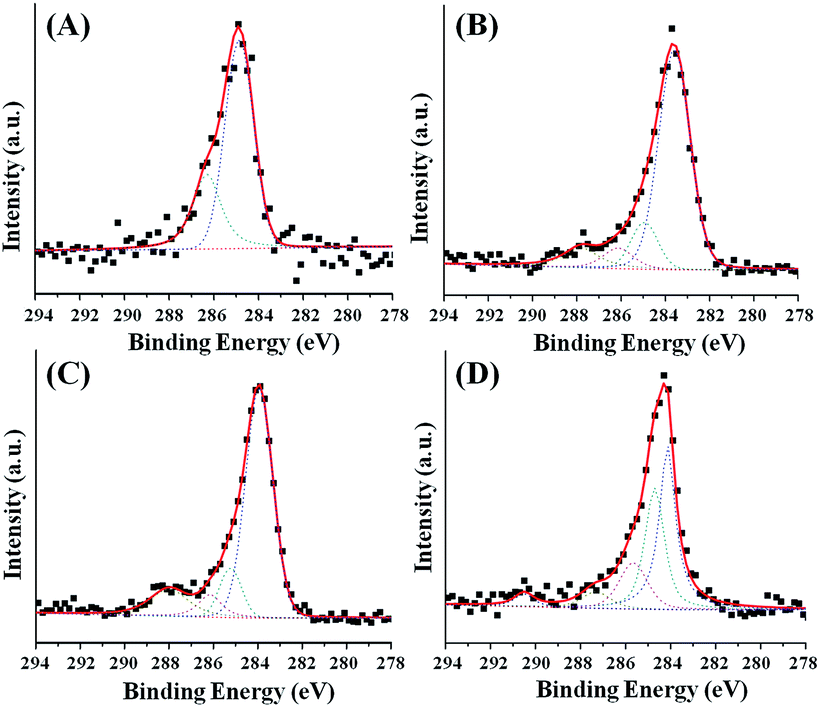 | ||
| Fig. 5 XPS data of Carbon. (A), (B), (C) and (D) are correlated with the four types mentioned in Fig. 4. | ||
 | ||
| Fig. 6 XPS data of Oxygen. (A), (B), (C) and (D) are correlated with the four types mentioned in Fig. 4. | ||
 | ||
| Fig. 7 XPS data of Al. (B) and (C) are correlated with the two types mentioned in Fig. 4. | ||
Neither H2O nor N2 contains C, so TMA is the only source of C. Decomposition of TMA on Si (100) wafer has been observed incompletely.25 Since the peak of C–Al is not detected, all the TMA has participated in either main or side reactions.26,27 Reactions of TMA and –OH are able to generate intermediate reactants (–O)(–OH)Al(CH3)2 and (–O)2(–OH)Al(CH3).28,29 O–O bond is not stable and alkyl peroxide has been found decomposable into ketone and alcohol.30 Besides generating C2H6, CH3˙ can react with ROR and generate CH4 and ROR˙, where R represents alkyl groups.31 These radicals can contribute to the formation of C-containing by-products. Since no gas with m/z above 45 is observed, C–O, CO and O–H containing chemicals are all emitted as aerosols at outlet of the pump.
EDS analysis of chemicals deposited on Si wafer
Measurements of atomic concentration of the 10 samples are also accomplished by EDS. The results are listed in Table S1 in the ESI.† Among these 10 samples, samples 4 to 9 locate in a relatively stable region. Sample 4 has higher concentration of carbon but its UV-Vis spectrum and XPS data are similar with other samples in type (B). This phenomenon is due to the stop valve installed between sample 3 and 4. C is detected on all the samples, indicating that side reactions are found all over the system. Concentration of Al from sample 5 to 9 does not change significantly, while concentrations of C and O both increase gradually. Therefore, reaction that generates Al2O3 is stable to a certain extent, while side reactions that generate C-containing chemicals accelerate along the pipeline. At the lower part of system, where sample 8 and 9 are placed, there are more C-containing chemicals generated than Al-containing chemicals. EDS measured on particles collected on TEM grid shows that 4.40 ± 1.00% of Al, 3.31 ± 1.07% of C, 83.46 ± 16.11% of Cu, 4.96 ± 0.96% of F and 3.86 ± 0.74% of O are containing in emitted particles.Conclusions
Both gaseous emissions and aerosols from ALD of Al2O3 process are investigated and reported. In the measurement of gaseous emission, CH4 and C2H6 are found generated by ALD reactions, where CH4 is the second concentrated component in the gaseous emission. Large amounts of aerosols that are 3 to 10 times more concentrated than average global aerosols are generated. Most of them are in the ultrafine range with diameter smaller than 100 nm. Purging time has no effects on aerosol size distribution, but significantly impacts the total net emission of aerosols. In a longer purging time, more aerosols are adsorbed on system pipeline as precipitation. Series measurements of samples collected along ALD exhaust system reflected the emission generation mechanism from both main and side chemical reactions. Aerosols emitted from the ALD reactions have both Al-containing and C-containing compounds, where C-containing compounds are generated through side reactions. XPS shows that chemical bonds, including C–H, C–O and CO, are contained in by-products. The main reactions can be considered stable to a certain extent, while side reactions accelerate and exceed the speed of main reactions at the last three samples.
Acknowledgements
This research is supported by National Science Foundation (CMMI-1200940). The author would also like to thank Jianyang Li, Xianfeng Gao and Dongsheng Guan for their assistance in the experiments.Notes and references
- M. Huang, Y. Chang, C. Chang, Y. Lee, P. Chang, J. Kwo, T. Wu and M. Hong, Appl. Phys. Lett., 2005, 87, 252104 CrossRef PubMed.
- P. Ye, B. Yang, K. Ng, J. Bude, G. Wilk, S. Halder and J. Hwang, Appl. Phys. Lett., 2005, 86, 063501 CrossRef PubMed.
- X. Gao, J. Chen and C. Yuan, J. Power Sources, 2013, 240, 503–509 CrossRef CAS PubMed.
- X. Gao, D. Guan, J. Huo, J. Chen and C. Yuan, Nanoscale, 2013, 5, 10438–10446 RSC.
- S. George, Chem. Rev., 2010, 110, 111–131 CrossRef CAS PubMed.
- E. Langereis, M. Creatore, S. Heil, M. van de Sanden and W. Kessels, Appl. Phys. Lett., 2006, 89, 081915 CrossRef PubMed.
- M. Pellin, P. Stair, G. Xiong, J. Elam, J. Birrell, L. Curtiss, S. George, C. Han, L. Iton, H. Kung, M. Kung and H. Wang, Catal. Lett., 2005, 102, 127–130 CrossRef CAS PubMed.
- J. Koo, S. Kim, S. Jeon and H. Jeon, J. Korean Phys. Soc., 2006, 48, 131–136 CAS.
- J. Huo, X. Lin and C. Yuan, Proceedings of 2012 ASME Manufacturing Science and Engineering Conference, Notre Dame, Indiana, USA, June 4–8, 2012 Search PubMed.
- D. Lashof and D. R. Ahuja, Nature, 1990, 344, 529–531 CrossRef CAS.
- P. Forster, V. Ramaswamy, P. Artaxo, T. Berntsen, R. Betts, D. Fahey, J. Haywood, J. Lean, D. Lowe, G. Myhre, J. Nganga, R. Prinn, G. Raga, M. Schulz and R. Van Dorland, Changes in Atmospheric Constituents and in Radiative Forcing. In Climate Change 2007: The Physical Science Basis, Contribution of Working Group I to the Fourth Assessment Report of the Intergovernmental Panel on Climate Change, ed. S. Solomon, D. Qin, M. Manning, Z. Chen, M. Marquis, K. Averyt, M. Tignor and H. Miller, Cambridge University Press, Cambridge, United Kingdom and New York, NY, USA, 2007, pp. 210–216 Search PubMed.
- D. Krewski, R. Yokel, E. Nieboer, D. Borchelt, J. Cohen, J. Harry, S. Kacew, J. Lindsay, A. Mahfouz and V. Rondeau, J. Toxicol. Environ. Health, Part B, 2007, 10, 1–269 CAS.
- U. Pöschl, Angew. Chem., Int. Ed., 2005, 44, 7520–7540 CrossRef PubMed.
- Trimethylaluminum; MSDS No. 98-4003, Strem Chemicals, Inc, Newburyport, MA, April 21, 2011 Search PubMed.
- K. Cashdollara, I. Zlochowera, G. Greena, R. Thomasa and M. Hertzberg, J. Loss Prev. Process Ind., 2000, 13, 327–340 CrossRef.
- J. Kim, D. Kwon, K. Chakrabarti, C. Lee, K. Oh and J. Lee, J. Appl. Phys., 2002, 92, 6739 CrossRef CAS PubMed.
- D. Squire, C. Dulcey and M. Lin, J. Vac. Sci. Technol., B: Microelectron. Process. Phenom., 1985, 3, 1513 CAS.
- D. Spracklen, K. Carslaw, J. Merikanto, G. Mann, C. Reddington, S. Pickering, J. Ogren, E. Andrews, U. Baltensperger, E. Weingartner, M. Boy, M. Kulmala, L. Laakso, H. Lihavainen, N. Kivekäs, M. Komppula, N. Mihalopoulos, G. Kouvarakis, S. Jennings, C. O'Dowd, W. Birmili, A. Wiedensohler, R. Weller, J. Gras, P. Laj, K. Sellegri, B. Bonn, R. Krejci, A. Laaksonen, A. Hamed, A. Minikin, R. Harrison, R. Talbot and J. Sun, Atmos. Chem. Phys., 2010, 10, 4775–4793 CrossRef CAS.
- K. Hyllestad, Scaling of Calcium Carbonate on a Heated Surface in a Flow Through System with Mono Ethylene Glycol, M.S. thesis, Norwegian University of Science and Technology, Trondheim, Norway, 2008.
- M. Crabtree, D. Eslinger, P. Fletcher, M. Miller, A. Johnson and G. King, Oilfield Rev., 1999, 11, 30–45 CAS.
- G. Dingemans and W. Kessels, J. Vac. Sci. Technol., A, 2012, 30, 040802 Search PubMed.
- G. López, P. Ortega, C. Voz, I. Martín, M. Colina, A. Morales, A. Orpella and R. Alcubilla, Beilstein J. Nanotechnol., 2013, 4, 726–731 CrossRef PubMed.
- A. Namiki, K. Tanimoto, T. Nakamura, N. Ohtake and T. Suzaki, Surf. Sci., 1989, 222, 530–554 CrossRef CAS.
- T. Kubo, J. Freedsman, Y. Iwata and T. Egawa, Semicond. Sci. Technol., 2014, 29, 045004 CrossRef.
- T. Gow, R. Lin, L. Cadwell, F. Lee, A. Backman and R. Masel, Chem. Mater., 1989, 4, 406–411 CrossRef.
- M. Bou, J. Martin and T. LeMogne, Appl. Surf. Sci., 1991, 47, 149–161 CrossRef CAS.
- C. Hinnen, D. Imbert, J. Siffre and P. Marcus, Appl. Surf. Sci., 1994, 78, 219–231 CrossRef CAS.
- A. Delabie, S. Sioncke, J. Rip, S. Elshocht, G. Pourtois, M. Mueller, B. Beckhoff and K. Pierloot, J. Vac. Sci. Technol., A, 2012, 30, 01A127 Search PubMed.
- B. Gongand and G. Parsons, J. Mater. Chem., 2012, 22, 15672 RSC.
- N. Kornblum and H. DeLaMare, J. Am. Chem. Soc., 1951, 73, 880–881 CrossRef CAS.
- P. Gray and A. Herod, Trans. Faraday Soc., 1986, 64, 2723–2734 RSC.
Footnote |
| † Electronic supplementary information (ESI) available. See DOI: 10.1039/c4ra14568b |
| This journal is © The Royal Society of Chemistry 2015 |