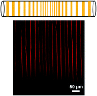
Self-assembly of large-scale P3HT patterns by confined evaporation in the capillary tube

Yingjuan Sunab, Guihua Xiaoab, Yuan Lin*a, Zhaohui Sua and Qian Wangac
aState Key Laboratory of Polymer Physics and Chemistry, Changchun Institute of Applied Chemistry, Chinese Academy of Sciences, Changchun 130022, PR China. E-mail: linyuan@ciac.ac.cn
bUniversity of Chinese Academy of Sciences, Beijing, 100049, PR China
cDepartment of Chemistry and Biochemistry, University of South Carolina, 631 Sumter Street, Columbia, South Carolina 29208, USA

Received 5th November 2014 , Accepted 12th February 2015

First published on 13th February 2015


Abstract

A facile and robust route to fabricate large area patterns of poly(3-hexylthiophene) (P3HT) was developed by controlled evaporative self-assembly (CESA) technique within a confined space (capillary tubes). Properties of P3HT, solvents effects and inner surface properties of the capillary tube were systematically investigated. The results showed that the patterns could be controlled to evolve from dot deposits and stripes with fingering instabilities, to highly regular, nearly perfect stripes. The orientation of P3HT within an individual stripe was characterized through confocal polarized Raman spectroscopy at molecular level, which revealed that the backbone chains of P3HT were parallel to the contact line. This simple method therefore provides a universal approach to control the morphology of patterns and chain orientation of functional polymers simultaneously.

Introduction

Conjugated polymers such as poly(3-hexylthiophene) (P3HT) have attracted considerable interests due to their unique semiconducting properties, high environmental stability and potential applications in developing organic field effect transistors,1,2 light emitting diodes,3 and polymer photovoltaic cells.4 Because of the high anisotropy of charge transportation in conjugated systems, ordered alignment and arrangement of conjugated polymers play a decisive role in the electrical properties for the fabrication of optoelectronic devices.5–7 Recently, different methods for the alignment of polymer chains in a thin film and the organization of chains into a desired configuration have been reported.8–10 Uniaxial alignment of liquid-crystalline like conjugated polymer films could be produced by means of a nanoimprinting process.11 The orientation of conjugated backbones could be controlled to be parallel to the structures imprinted into the polymer film and parallel to the substrate. In addition, oriented P3HT films were also obtained by mechanical rubbing.12,13 Heil et al. showed that rubbing of P3HT could induce local chain orientation and polymer crystallization and lead to sizable anisotropic charge transport. Shklyarevskiy demonstrated that liquid crystal in mesoscopic orders could be obtained with a high magnetic field. More than up to 75 times enhancement of the field-effect mobility can be acheieved.3

However, most of the methods reported in the literatures are either complicated or expensive for the fabrication of ordered patterns in large-scales. Furthermore, simultaneous control of polymer chains alignment and organization is still a challenge. Consequently, simple patterning and aligning methods of conjugated polymers are highly desirable.

Recently, self-assembly methods have been applied to align conjugated polymer chains.14 For instance, the use of supramolecular self-assembly methods,15 LB film deposition technology16 and self-assembly methods based on evaporation like controlled evaporative self-assembly (CESA).17,18 Using these molecular self-assembly techniques, especially the self-assembly approaches occur at the interface, can achieve an orderly arrangement of molecules through evaporation and drying.19,20 Among them, CESA is a simple, rapid, economical method with good controllability and has access to a rich and large-area varied topography.21 In our group, rod-like virus particles, like tobacco mosaic virus (TMV)22 has been applied to construct different scaffolding materials for support cell growth using the CESA method. For instance, taking advantage of the anisotropic property of TMV, the orientation of TMV could be controlled either parallel or perpendicular to the tubing long-axis.23 Since the P3HT is a semi-rigid chain, the anisotropic property will make it be a potential candidate to align on the CL. The chain orientation within the assembled patterns would affect the direction of charge transfer and electrical properties.24

In this present work, we introduced a facile way to control the self-assembly behavior of conjugated polymer system within a confined space (capillary tubes) via CESA. P3HT solution dissolved in several organic solvents was placed into the glass capillary tube and large-scale symmetrical patterns were formed from both ends on the inner surface of the capillary tube upon drying. Properties of P3HT, solvents effects and inner surface properties of the capillary tube are key factors to influence the self-assembly process in the capillary tube. This method can potentially be applied in the self-assembly of other conductive polymers.

Experimental

Materials

Regioregular P3HT (Mw = 45[thin space (1/6-em)]000 Da, PDI = 2.0, RR = 98%) was purchased from Rieke Metals Inc. 3-Aminopropyltriethoxysilane (APTES) and poly(diallyldimethylammonium chloride) (PDDA) aqueous solution with Mw = 250[thin space (1/6-em)]000–300[thin space (1/6-em)]000 Da from Sigma-Aldrich. All the solvents (analytically pure) employed in our experiments were purchased from Beijing Chemical Works and used as received. For simplicity, we adopt the abbreviation or chemical formula of some solvents, which are denoted as follows: chloroform (CF), toluene (MB), carbon disulfide (CS2), chlorobenzene (CB). The glass capillary tubes (inner diameter ∼0.15 cm, outer diameter ∼0.18 cm) from KIMBLE Co. were cleaned with a piranha solution (7[thin space (1/6-em)]:[thin space (1/6-em)]3 mixture of 98% H2SO4 and 30% H2O2) at 80 °C for 2 h (Caution! Piranha solution reacts violently with organic materials.), then washed with deionized water three times and dried by nitrogen flow.

General procedure

P3HT solution dissolved in different solvents (25 μL) was trapped into the capillary tube and the tubes were maintained in a horizontal position on the flat bench at room temperature 23 ± 2 °C and 20–30% humidity. The temperature and humidity were monitored by a temperature-hygrometer (Hygrometer Testo 608-H1, Germany). After evaporation of the solvents, large area parallel stripes were obtained on the inner surface of the glass capillary tubes.

Characterization

Optical microscopy measurements were obtained on a Carl Zeiss A1m microscope. Atom force microscope was carried out by an Agilent 5500 AFM in an ambient atmosphere by tapping mode. Confocal laser scanning microscopy was characterized on LSM 700 with a Carl Zeiss microscope. Contact angle was tested on a droplet shape analyzer Krüss DSA 10-MK2 with 3 μL droplet volume. Raman spectra were obtained with LabRam HR800 spectrometer (Horiba Jobin Yvon) with an Olympus BX41 microscope in the back scattering geometry. A 632.8 nm He–Ne laser was focused on the sample with a 50× objective lens. Stripes were aligned along the Z direction (perpendicular to the direction of tube long-axis) and polarized spectra were recorded in the order: ZZ, XX, ratios were obtained by measuring the intensity ten different points in one stripe at different positions in the tubes. We define Z direction as that parallel to the long axis of the stripe and X perpendicular to the stripe long axis in the sample plane. For the measurements with polarized light, we use two configurations, ZZ and XX, using the notation “incident polarization analyzed polarization”.

Results and discussion

Principles of the formation of P3HT stripes patterning in a capillary tube

When P3HT solution is dried in an open-ended horizontally laid capillary tube, a symmetrical pattern is formed from both ends. This process is similar to that of drying colloidal and nanoparticle solutions in the capillary tubes.25 As shown in Fig. 1a–c, when the P3HT solution was injected into the capillary tube, a thin meniscus formed at the three-phase contact interface first (see the photograph in Fig. S1, ESI). Convective flow drives P3HT molecules to move toward the contact line (CL) and deposit on the substrate as the solvents evaporate.26 Deposition of solutes will generate a frictional force f, which together with the surface tension of the film γf pins the position of the CL. Solvents surface tension γL is a kind of depinning force. The CL then slips and reaches to another equilibrium position, where the solvent is back in contact with the glass surface. Consequently, the process repeats periodically, and the resulting “stick-slip” motion forms a parallel pattern.27,28 When P3HT solution was injected into the capillary tube by capillary force, the evaporation of solvents was restricted to occur at the capillary edge. Evaporative loss of solvents at the edge was replenished by the interior liquid. P3HT was carried to the periphery by the outward flow and then deposited along the CL. Apparently, only the surface tension of the solvents directly contributes to the depinning force and may significantly influence the assembled patterns. Meanwhile, the boiling point of the solvent affects the evaporation rate as well as the deposition amount of solute, and thus indirectly affect the friction force. Therefore, properties of P3HT, solvents effects and inner surface properties of the capillary tube are key factors to the pattern formation.
image file: c4ra13893g-f1.tif
Fig. 1 Schematic illustration of P3HT stripes formation in a capillary tube by a drying process. (a) A capillary tube containing P3HT in organic solvents, black arrows indicate drying direction. The tube was divided into 5 positions from outside to inside marked as position 1 and 5, position 2 and 4, and the center of the tube was marked as position 3. (b) Structure of P3HT. (c) Illustration of the thin meniscus formed at the CL, indicated by black dashed square in (a). P3HT molecular chains are represented as yellow chains, nanowhiskers are indicated as blue blocks. The red arrow represents direction of the frictional force f generated by deposition of P3HT molecules at the CL. Two thin black arrows represent droplet's surface tension γL and the wetting film's surface tension γf. The contact angle between the solvents and substrate is θ. (d) Schematic illustration of the nanowhiskers self-assembled by P3HT chains along the π–π stacking direction upon aging process. The interaction between the adjacent light blue sheets is π–π stacking interaction, the distance between the adjacent sheets is π–π stacking distance and the blue arrow indicates the wire axis of P3HT nanowhiskers.

Concentration effects on the self-assembly of P3HT

For a P3HT solution, driven by the π–π interaction, the solution is easy to self-assemble into nanowhiskers from the molecular chains24 (Fig. 1d). With the aging process of the solution, the content of single molecule chains reduced and the length of the nanowires increased.29 Our previous study has reported that P3HT nanowhiskers formed in the CF aged solution as well as at high concentration.30 Though the nanowhiskers can greatly increase the charge mobility, it is quite challenging in aligning the nanowhiskers due to its high viscosity and poor rigid properties. Compared to the nanowhiskers, the single molecule chains should be easy to control its chain orientation attributes to its high mobility and flexibility. Based on this, the fresh prepared P3HT in CF solutions at low concentrations (from 0.02 mg mL−1 to 1 mg mL−1) were chosen to be studied. When the concentration was too low (0.02 mg mL−1), there was not enough P3HT molecules to be driven to the CL to deposit during pinning, so no ordered structures were obtained (Fig. 2a). P3HT at relative higher concentration (i.e. 0.1–0.5 mg mL−1) could make more solutes deposit at the contact line, it was more beneficial to fix the CL (Fig. 2b and c), so much regular stripes were obtained. Further increased the concentration to 1 mg mL−1, a continuous film instead of stripes was formed (Fig. 2d). This was due to that at higher concentrations, more solutes could be deposited at the CL. The generated friction force f (Fig. 1c) increases, together with the surface tension of the film γf, which is much larger than the solvents surface tension γL. Hence the contact line cannot be depinned, and no stripe patterns were observed.23 According to the above results, we fixed the concentration of P3HT at 0.1 mg mL−1 in the following studies.
image file: c4ra13893g-f2.tif
Fig. 2 Optical microscopy images of patterns formed at position 1 by self-assembly of P3HT in freshly prepared CF solution at different concentrations: (a) 0.02 mg mL−1, (b) 0.1 mg mL−1, (c) 0.5 mg mL−1 and (d) 1 mg mL−1. Scale bars are all 100 μm.

Solvents effects on the self-assembly of P3HT

It is well known that solvents with moderate evaporation rate, better solubility and low surface tension can enhance the mobility of polymer chains, which is in favor of the orientation and assembly process.31,32 Therefore, evaporation rate, solubility of solvents and surface tension were carried out to study the influence of chains orientation and self-assembling behaviors on the CL. Different solvents were selected and their physical properties (data was compiled from Yaws, C. L., Yaws' handbook of thermodynamic and physical properties of chemical compounds, 2003) were listed in Table 1.
Table 1 Physical properties of selected organic solvents to dissolve P3HT
Solvents CF MB CS2 CB
Boiling point (°C) 61.18 110.63 46.22 131.72
Surface tension (mN m−1) 26.68 27.93 31.56 32.93
Solubility parameter ((cal per cm3)1/2) 9.30 8.97 9.98 9.29


Evaporation rate effects on the self-assembly of P3HT

As shown in Fig. 1c, the evaporative loss of solvents at the edge is replenished by the interior liquid, therefore, a suitable evaporation rate is required to not only transport the P3HT to the edge, but also have enough time for P3HT molecular chains to align at the CL and form the regular pattern. Meanwhile, the evaporation rate varies spatially in the capillary tube, with the fastest rate at the edge of the tube. The spatial variation of evaporative flux and convection, these in turn leading to the pinning force and the depinning force in nonequilibrium.21 And since the “stick-slip” motion of the contact line was governed by the competition between the linear pinning force and the nonlinear depinning force,31 so the gradient stripes were finally fabricated for a CF solution of P3HT (Fig. 3). Both the center-to-center distance between adjacent stripes (λC–C) and the height of the stripes decreased with increasing proximity to the center of the tube (Fig. 3d). For example, the λC–C decreased from 40 μm (position 1), 26 μm (position 2) to 14 μm (position 3) and the height evolved from 70 nm, 47 nm to 31 nm at the corresponding positions. And at the same time, the regularity of the patterns improved gradually from outside to inside along with the evaporation proceed. Such as, the stripes evolved from fingering instability (Fig. 3a), some fingering instability and dotted line (Fig. 3b) to dotted line (Fig. 3c) in morphology. If we further increased length of the tube to 4 cm and 6 cm, the morphologies were similar with that in 2.2 cm tube (Fig. 3) in some extent. However, the stripes were not obvious at the position 3 (near the center of the tube) in a 6 cm tube, nearly continuous film. Meanwhile, another solvent MB with a higher boiling point (lower evaporation rate) but similar surface tension with CF was chosen to study the evaporation rate effect.
image file: c4ra13893g-f3.tif
Fig. 3 Confocal microscopy images (a–c) of the stripes formed by 0.1 mg mL−1 CF solution of P3HT in the capillary tube at (a) position 1, (b) position 2, and (c) position 3. (d) Relationship of height and distance between adjacent stripes (λC–C) at different positions. The definition of λC–C and height is illustrated in the inset of (d).

As shown in Fig. 4a–c, much more ordered stripes could be found nearly at all places in the whole tube for a MB solution of P3HT. From the positions outside to inside in the tube, the regularity of the stripes was gradually improved with the evaporation proceed. There were still some small protrusions in the stripes at position 1 as shown in Fig. 4a. And when came to position 2 (Fig. S2a), the stripes became more straight and regular. These results indicated that a suitably slower evaporation rate can depress the development of fingering instability and improve the regularity of the patterns, which is consistent with the report by Han and coworkers.33,34


image file: c4ra13893g-f4.tif
Fig. 4 Confocal microscopy images (a and d) and AFM images (b, c, e and f) of stripes at the position 1 (see Fig. 1a) from 0.1 mg mL−1 P3HT solution in different solvents self-assembled in the capillary tube: (a–c) for MB; (d–f) for CF/MB (v/v = 1/1). Images (b and e) are enlarged views of the white dashed square in (a and d). Images (c and f) are enlarged views of the white dashed square in (b and e), respectively.

Solubility effects on the self-assembly of P3HT

The solubility parameter of P3HT is 9.50 (cal per cm3)1/2.35 However, P3HT chains cannot be completely dissolved or even sediment from the MB due to the poor solubility (see solubility parameter in Table 1). Though CF is a good solvent to P3HT, it has a fast evaporation rate. While the mixed solvents36,37 would combine their respective advantages, in which P3HT chains not only have sufficient time but also have adequate molecular mobility to align at the CL and thus highly-ordered hierarchical structures can be obtained. Consequently, by assembling a CF/MB (v/v = 1/1) solution of P3HT, we fabricated regular, uniform and parallel stripes almost in the whole tube (position 1 in Fig. 4d and position 2 in Fig. S2d) and the chains orientation in individual stripe will be discussed in the later paragraph. From the AFM images (Fig. 4b and e and Fig. S2), we observed nanowhiskers closely packed together in individual stripe. These nanowhiskers were formed in the assembling process because the P3HT solution was heated enough to guarantee P3HT fully dissolved before the solutions were injected into the capillary tube. For the nanowhiskers formation, we speculated that these nanowhiskers formed in the solution or on the CL during the evaporation process. This is because, as the evaporation proceeded, evaporation rate became slower and the concentration changed, which may lead to nanowhiskers form. These nanowhiskers formed in the solution preferred to align parallel to the CL in order to decrease the interface energy.30 At the same time, during the drying process, an outward flow diffused from the bulk to replenish the evaporation losses at the perimeter, which took P3HT molecules from the bulk solution, to the edges and align parallel to the CL. When it reached to a certain threshold value of concentration, P3HT molecules began to form nanowhiskers on the CL and these nanowhiskers aligned perpendicular to the CL. The deposition not only provides as a pinning force but also serve as a nucleation point for P3HT nanowhiskers formation, which is consistent with the report by Zhang38 that concentric organic semiconductor N,N′-dimethylquinacridone (DMQA) nanowires arrays formed on the substrate with the alignment perpendicular to the contact line. This is the reason why some nanowhiskers could be observed that aligned perpendicular to the edges of the stripes (Fig. 4f).

Surface tension effects on the self-assembly of P3HT

As a kind of depinning force in the self assembly process, γL (Fig. 1c) is influenced by the solvents surface tension and plays an important role in the assembly behavior in the capillary tube.23 As we mentioned above, both CF and MB are lower surface tension solvents, so the depinning force was not too high and regular stripe patterns were observed. Oppositely, two kinds of higher surface tension solvents like carbon disulfide (CS2) and chlorobenzene (CB) were chosen to compare.32 CS2 solution of P3HT can self-assemble into random deposits in the whole tube (Fig. 5a and b), while in CB solution of P3HT, similar to the P3HT in CF solution,30 but few fingering instability, nearly continuous and irregular line were formed (Fig. 5c and d). When the concentration was fixed at 0.1 mg mL−1, the surface tension γL was too high to fix the CL for CS2, which resulted in the CL getting depinned easily and the stripes were parallel to the long-axis of the tube. However, though the CB with the high surface tension, with respect to the high boiling solvent (CB), lower evaporation rate, more P3HT was evaporated to the CL by convection flow. This structure is consistent with the results of the dot deposition of the low molecular weight PS for the CL cannot be fixed.20 These results showed that the surface tension influenced the formation of the stripes and higher surface tension was not beneficial to the stripes formation in the capillary tubes.
image file: c4ra13893g-f5.tif
Fig. 5 Optical microscopy images of patterns self-assembled by 0.1 mg mL−1 CS2 solution of P3HT (a and b), 0.1 mg mL−1 CB solution of P3HT (c and d) at the position 1 in the capillary tube. Images (b and d) are enlarged views of (a and c), respectively. Scale bars for (a and c) are 200 μm, for (b and d) are 100 μm.

Inner surface properties of the self-assembly of P3HT

In order to form a stripe pattern, the contact angle between water and the substrate must be smaller than the contact angle between water and P3HT (θP3HT = 105°).23 Furthermore, the surface hydrophobicity properties are related to the interaction between the solutes and the substrate, which is related to the film stability.21 Therefore, another two modified surfaces with PDDA and APTES that have different hydrophobicity but similar surface roughness39,40 to glass were prepared. The modification with APTES, afforded a much more hydrophobic (the contact angle was ∼45°) than that of PDDA (the contact angle was ∼15°) and the fresh cleaned glass tube (the contact angle was ∼5°). As expected, for a fresh CF solution of P3HT (0.1 mg mL−1), stripe patterns were observed on these two surfaces. However, unlike the slim stripes with fingering instability in the glass tube (Fig. 3a), regular stripes could be observed in the inner surfaces of both modified glass tubes, especially in the APTES surface (Fig. 6). Considering the P3HT molecules did not carry any charge, so here only the hydrophobic force was contributed to the interaction between the solutes and the substrate. The hydrophobic interaction between P3HT and APTES is much stronger than that of P3HT and glass surface, which helps to govern the stability of the P3HT thin film and leading to more regular stripes.21,33
image file: c4ra13893g-f6.tif
Fig. 6 Optical microscopy images of patterns self-assembled by a CF solution of P3HT (0.1 mg mL−1) at the position 1 in the capillary tube. (a and b) In the PDDA modified glass tube; (c and d) in the APTES modified glass tube. Images (b and d) are enlarged views of the white dashed square in (a and c), respectively. Scale bars are 100 μm for (a and c) and 20 μm for (b and d).

Raman spectroscopy of stripes self-assembled in the capillary tube

Polarized Raman spectroscopy is an effective and robust technique to quantify the molecular orientation and has been applied in the study of P3HT in literatures.41 Raman anisotropy at 1445 cm−1 peak could be used to monitor the molecular orientation of P3HT backbones within the stripes.42,43 When P3HT solution is dried in an open-ended horizontally laid capillary tube, a symmetrical pattern is formed from both ends, so position 1 and position 5 as well as position 2 and 4 were the same in morphology and chain orientation values. As shown in Fig. 7, for the stripes at the position 1 and 5 formed by evaporating a CF/MB (v/v = 1/1) solution of P3HT, the Raman orientation data give a high IZZ/IXX (∼2.3), indicating that P3HT backbones aligned parallel to the CL. Similar values were observed in the stripes formed by CF solution (∼1.8) and MB solution (∼2.0). Just as mentioned above, the nanowhiskers formed in the solution or at the CL during the evaporation process. The anisotropic nanowhiskers tended to arrange parallel or perpendicular to the CL depending on the nanowhiskers formed in solution or on the CL, and the single molecular chain made the molecular chain parallel to the CL. The competition between the single molecule chains and nanowhiskers in molecular orientation caused the IZZ/IXX decreased. At the position 3 in the center of the tube, the IZZ/IXX was around 1.0, represented nearly random arrangement of P3HT chains. These results above suggested that drying P3HT solutions was a complicated process in the capillary tube, because multiple components coexist in the P3HT solutions.
image file: c4ra13893g-f7.tif
Fig. 7 Raman anisotropy (IZZ/IXX) of the 1445 cm−1 peak of the stripes at different positions in the capillary tubes.

Conclusion

In summary, we have successfully gained large area stripe patterns of a prototypical conjugated polymer, P3HT, based on confined evaporation method within the capillary tube. An evolution of morphology was observed and the chain orientations of P3HT in individual stripe were characterized. We found that backbone chains of P3HT were always parallel to the contact line. Properties of P3HT, solvent effects and inner surface properties all play important roles in the self-assembly process. This approach can be readily applied in the alignment of other conjugated polymers in large-scale and potentially to be used in a variety of application fields.

Acknowledgements

This work was financially supported by the National Natural Science Foundation of China (21374119 and 21429401). YL and QW are grateful of the support from the State Key Laboratory of Polymer Physics and Chemistry of the Chinese Academy of Sciences. YL also acknowledges the financial support from Project supported by State key laboratory of precision measuring technology and instruments (Tianjin University).

References

  1. Z. Bao, A. Dodabalapur and A. J. Lovinger, Appl. Phys. Lett., 1996, 69, 4108–4110 CrossRef CAS PubMed .
  2. J. Locklin, D. Li, S. C. B. Mannsfeld, E.-J. Borkent, H. Meng, R. Advincula and Z. Bao, Chem. Mater., 2005, 17, 3366–3374 CrossRef CAS .
  3. I. O. Shklyarevskiy, P. Jonkheijm, N. Stutzmann, D. Wasserberg, H. J. Wondergem, P. C. M. Christianen, A. Schenning, D. M. de Leeuw, Z. Tomovic, J. S. Wu, K. Mullen and J. C. Maan, J. Am. Chem. Soc., 2005, 127, 16233–16237 CrossRef CAS PubMed .
  4. G. Zhao, Y. He and Y. Li, Adv. Mater., 2010, 22, 4355–4358 CrossRef CAS PubMed .
  5. X. F. Duan, Y. Huang, Y. Cui, J. F. Wang and C. M. Lieber, Nature, 2001, 409, 66–69 CrossRef CAS PubMed .
  6. J. A. Merlo and C. D. Frisbie, J. Phys. Chem. B, 2004, 108, 19169–19179 CrossRef CAS .
  7. X. F. Duan, C. M. Niu, V. Sahi, J. Chen, J. W. Parce, S. Empedocles and J. L. Goldman, Nature, 2003, 425, 274–278 CrossRef CAS PubMed .
  8. Y. Yamamoto, Sci. Technol. Adv. Mater., 2012, 13, 033001 CrossRef .
  9. Z. Yin and Q. Zheng, Adv. Energy Mater., 2012, 2, 179–218 CrossRef CAS .
  10. F. S. Kim, G. Ren and S. A. Jenekhe, Chem. Mater., 2011, 23, 682–732 CrossRef CAS .
  11. M. Aryal, K. Trivedi and W. Hu, ACS Nano, 2009, 3, 3085–3090 CrossRef CAS PubMed .
  12. G. Derue, S. Coppee, S. Gabriele, M. Surin, V. Geskin, F. Monteverde, P. Leclere, R. Lazzaroni and P. Damman, J. Am. Chem. Soc., 2005, 127, 8018–8019 CrossRef CAS PubMed .
  13. G. Derue, D. A. Serban, P. Leclere, S. Melinte, P. Damman and R. Lazzaroni, Org. Electron., 2008, 9, 821–828 CrossRef CAS PubMed .
  14. M. Takeuchi, C. Fujikoshi, Y. Kubo, K. Kaneko and S. Shinkai, Angew. Chem., Int. Ed., 2006, 45, 5494–5499 CrossRef CAS PubMed .
  15. Y. Kubo, Y. Kitada, R. Wakabayashi, T. Kishida, M. Ayabe, K. Kaneko, M. Takeuchi and S. Shinkai, Angew. Chem., Int. Ed., 2006, 45, 1548–1553 CrossRef CAS PubMed .
  16. V. Cimrova, M. Remmers, D. Neher and G. Wegner, Adv. Mater., 1996, 8, 146–149 CrossRef CAS .
  17. M. Byun, R. L. Laskowski, M. He, F. Qiu, M. Jeffries-El and Z. Lin, Soft Matter, 2009, 5, 1583–1586 RSC .
  18. B. Li, W. Han, M. Byun, L. Zhu, Q. Zou and Z. Lin, ACS Nano, 2013, 7, 4326–4333 CrossRef CAS PubMed .
  19. C. J. Hawker and T. P. Russell, MRS Bull., 2005, 30, 952–966 CrossRef CAS .
  20. B. Li, W. Han, B. Jiang and Z. Lin, ACS Nano, 2014, 8, 2936–2942 CrossRef CAS PubMed .
  21. Z. Lin, J. Polym. Sci., Part B: Polym. Phys., 2010, 48, 2552–2557 CrossRef CAS .
  22. X. Zan, S. Feng, E. Balizan, Y. Lin and Q. Wang, ACS Nano, 2013, 7, 8385–8396 CrossRef CAS PubMed .
  23. Y. Lin, E. Balizan, L. A. Lee, Z. Niu and Q. Wang, Angew. Chem., Int. Ed., 2010, 49, 868–872 CrossRef CAS PubMed .
  24. S. Samitsu, T. Shimomura, S. Heike, T. Hashizume and K. Ito, Macromolecules, 2008, 41, 8000–8010 CrossRef CAS .
  25. M. Abkarian, J. Nunes and H. A. Stone, J. Am. Chem. Soc., 2004, 126, 5978–5979 CrossRef CAS PubMed .
  26. E. Adachi, A. S. Dimitrov and K. Nagayama, Langmuir, 1995, 11, 1057–1060 CrossRef CAS .
  27. Y. Lin, Z. Su, E. Balizan, Z. Niu and Q. Wang, Langmuir, 2010, 26, 12803–12809 CrossRef CAS PubMed .
  28. W. Han, B. Li and Z. Lin, ACS Nano, 2013, 7, 6079–6085 CrossRef CAS PubMed .
  29. S. Berson, R. De Bettignies, S. Bailly and S. Guillerez, Adv. Funct. Mater., 2007, 17, 1377–1384 CrossRef CAS .
  30. G. Xiao, Y. Guo, Y. Lin, X. Ma, Z. Su and Q. Wang, Phys. Chem. Chem. Phys., 2012, 14, 16286–16293 RSC .
  31. J. Xu, J. F. Xia, S. W. Hong, Z. Q. Lin, F. Qiu and Y. L. Yang, Phys. Rev. Lett., 2006, 96, 066104 CrossRef .
  32. W. Xu, L. Li, H. Tang, H. Li, X. Zhao and X. Yang, J. Phys. Chem. B, 2011, 115, 6412–6420 CrossRef CAS PubMed .
  33. W. Han and Z. Lin, Angew. Chem., Int. Ed., 2012, 51, 1534–1546 CrossRef CAS PubMed .
  34. W. Han, M. He, M. Byun, B. Li and Z. Lin, Angew. Chem., Int. Ed., 2013, 52, 2564–2568 CrossRef CAS PubMed .
  35. K. Zhao, Z. Ding, L. Xue and Y. Han, Macromol. Rapid Commun., 2010, 31, 532–538 CrossRef CAS PubMed .
  36. A. Yella, M. N. Tahir, S. Meuer, R. Zentel, R. Berger, M. Panthoefer and W. Tremel, J. Am. Chem. Soc., 2009, 131, 17566–17575 CrossRef CAS PubMed .
  37. J. A. Lim, W. H. Lee, H. S. Lee, J. H. Lee, Y. D. Park and K. Cho, Adv. Funct. Mater., 2008, 18, 229–234 CrossRef CAS .
  38. Z. Wang, R. Bao, X. Zhang, X. Ou, C.-S. Lee, J. C. Chang and X. Zhang, Angew. Chem., Int. Ed., 2011, 50, 2811–2815 CrossRef CAS PubMed .
  39. T. Y. Yung, L. Y. Huang, T. Y. Chan, K. S. Wang, T. Y. Liu, P. T. Chen, C. Y. Chao and L. K. Liu, Nanoscale Res. Lett., 2014, 9, 444 CrossRef PubMed .
  40. B. Wang, Z. Liu, Y. Xu, Y. Li, T. An, Z. Su, B. Peng, Y. Lin and Q. Wang, J. Mater. Chem., 2012, 22, 17954–17960 RSC .
  41. M. Baibarac, M. Lapkowski, A. Pron, S. Lefrant and I. Baltog, J. Raman Spectrosc., 1998, 29, 825–832 CrossRef CAS .
  42. M. Koppe, C. J. Brabec, S. Heiml, A. Schausberger, W. Duffy, M. Heeney and I. McCulloch, Macromolecules, 2009, 42, 4661–4666 CrossRef CAS .
  43. H.-L. Cheng, J.-W. Lin, M.-F. Jang, F.-C. Wu, W.-Y. Chou, M.-H. Chang and C.-H. Chao, Macromolecules, 2009, 42, 8251–8259 CrossRef CAS .

Footnote

Electronic supplementary information (ESI) available: Photograph of the capillary tube, OM and AFM images at position 2. See DOI: 10.1039/c4ra13893g

This journal is © The Royal Society of Chemistry 2015