
A green method to prepare TiO2/MWCNT nanocomposites with high photocatalytic activity and insights into the effect of heat treatment on photocatalytic activity
Qingping Zeng,
Hua Li*,
Huanan Duan,
Yiping Guo,
Xuefa Liu,
Yangyang Zhang and
Hezhou Liu*
State Key Laboratory of Metal Matrix Composites, School of Materials Science and Engineering, Shanghai Jiao Tong University, Dongchuan Road No. 800, Minhang District, Shanghai 200240, People's Republic of China. E-mail: lih@sjtu.edu.cn; hzhliu@sjtu.edu.cn; Tel: +86 021 34202549
First published on 9th January 2015
Abstract
Nanocomposites consisting of well-defined anatase TiO2 nanoparticles with an average diameter of 8 nm and multi-walled carbon nanotubes (MWCNTs) were fabricated by a facile two-step hydrothermal method using water as the main solvent, which is friendly to the environment and totally different from previous methods. The TiO2 nanoparticles were uniformly grafted on the surface of MWCNTs via intimate chemical bonds, which was beneficial for the enhancement of photocatalytic activity. The photocatalytic activities of as-prepared TiO2/MWCNT nanocomposites for degradation of rhodamine B under solar simulator illumination were investigated systemically. It was found that the photocatalytic activity of as-prepared TiO2/MWCNT nanocomposites was 7 times higher than that of pure TiO2 prepared via the same hydrothermal procedure. The enhancement was mainly due to the existence of MWCNTs, which could not only greatly improve the adsorption of rhodamine B, but also retard the recombination of photogenerated electron–hole pairs and absorb more light. The photocatalytic performance was further enhanced after being annealed at 400 °C and 500 °C for 1 h because of the improved crystallinity of anatase TiO2. Interestingly, the photocatalytic activities of samples annealed at 400 °C and 500 °C showed no difference, which was different from previous reports.
Introduction
Many photocatalysts including ZnO,1,2 CdS,3,4 TiO2 (ref. 5–7) and BiVO4 (ref. 8 and 9) have been intensively studied with the hope of addressing environmental problems relating to organic pollution. Among them, TiO2 attracts most interest due to its superior photocatalytic activity, cost-effectiveness, long-term chemical stability and relative nontoxicity. Anatase and rutile are the two main polymorphs of TiO2. Anatase possesses a significantly higher photocatalytic activity than rutile for the following reasons: (1) anatase shows a band-gap 0.2 eV larger than rutile, which endows anatase a higher redox potential; (2) anatase has a higher area density of surface hydroxyls, which slows the recombination of photogenerated electron–hole pairs; (3) the charge-carrier mobility in anatase is 80 cm2 V−1 s−1, which is 89 times faster than that in rutile.10 Owing to the superior properties of anatase, intensive attentions have been paid on synthesizing anatase TiO2 composites for photocatalytic applications in previous reports.11–14 Under the irradiation of ultraviolet (UV) light, TiO2 can generate electron–hole pairs. These electron–hole pairs create active species such as surface-associated OH radicals, photogenerated OH radicals and superoxides (O2), which participate in subsequent chemical reactions leading to the degradation of organic contaminants.15,16With all the merits mentioned above, TiO2 has its own limitations as a photocatalyst. Firstly, anatase TiO2 requires UV light to generate electron–hole pairs because of its relatively large bandgap. However, the UV light accounts for only 5% of the total sunlight spectrum, which means limited solar power can be utilized to generate the electron–hole pairs. Another limitation is the fast recombination rate of the photogenerated electron–hole pairs.15 Photogenerated electron–hole pairs have a recombination time on the order of 10−9 s, while the chemical interaction with adsorbed pollutant species has a time scale of 10−8 to 10−3 s.17 Thirdly, according to the Langmuir–Hinshelwood mechanism, the pollutants are firstly adsorbed by the photocatalyst before being degraded, thus the limited specific surface area of TiO2 nanoparticles would retard the degradation rate.18
In order to realize its commercial applications, great efforts have been made to extend the light absorption range, retard the recombination of photogenerated electron–hole pairs and enhance the pollutants adsorption. Activated carbon was initially used as a support for TiO2 in photodegradation studies18 due to its very large specific surface area that is more than one order of magnitude larger than that of P25. Increasing the specific surface area means an increase in the amount of the adsorbed pollutants and thus an enhancement of the photocatalytic activity. However, the resultant improvement is limited as a result of the narrow light absorption range and the still fast electron–hole pair recombination rate. To achieve a further enhancement, carbon nanotubes (CNTs) has been considered as a support material for TiO2 in virtue of its relatively large specific surface area and outstanding electronic properties.19,20 CNTs provide an even larger specific surface area than activated carbon.19 The various irregularities and defects on the surface of CNTs can serve as trap sites for the photogenerated electrons injected from TiO2 nanoparticles loaded on the surface of CNTs. CNTs have a large electron-storage capacity (one electron for every 32 carbon atoms),21 which may accommodate the photogenerated electrons from the nanostructured TiO2, thus prolonging the lifetime of the electron–hole pairs. The TiO2/CNT Schottky barrier junction is also effective to reduce the recombination rate as demonstrated by previous reports.22 Moreover, CNTs can act as photosensitizers in the TiO2/CNT composites as proposed by Wang et al.23 The existence of CNTs can extend the light absorption range of the composites thanks to the presence of the carbon–oxygen–titanium bond in the TiO2/CNT nanocomposites, which is similar to carbon-doped titanium. With the aforementioned superiority of CNTs, we expect that TiO2 nanoparticles will have a better photocatalytic activity after the introduction of carbon nanotubes. Several different methods have been developed including hydrothermal process,24,25 sol–gel route,23,26 hydrolysis, electrodeposition27 and electrospinning28 to synthesized TiO2/CNT nanocomposites. Sol–gel is the most common method,19 while the hydrothermal is a more effective method as hydrothermal-derived TiO2/CNT nanocomposites show better photocatalytic performance.29
In this paper, we employed a facile two-step hydrothermal method to synthesize well-defined anatase TiO2 nanoparticles/multi-wall CNT (MWCNT) nanocomposites using water as main solvent. Compared with previously reported methods,30,31 this method was more friendly to environment and the loading of TiO2 nanoparticles was better. The connection between TiO2 nanoparticles and MWCNTs was via Ti–O–C chemical bonds rather than simply physical adsorption, which was favorable to the enhancement of photocatalytic performance. In this method, we used oxidized MWCNTs in order to achieve uniform suspension before hydrothermal process, which was vital to realize uniform loading. The relatively photocatalytic activity of the obtained TiO2/MWCNT nanocomposites was characterized by photodegradation of rhodamine B under solar simulator illumination. We also studied the effect of the crystallinity of anatase TiO2 on the enhancement of photocatalytic activity. By annealing the as-prepared TiO2/MWCNT nanocomposites at 400 °C and 500 °C for 1 h, a further enhancement of photocatalytic activity was realized.
Experimental
Oxidation of MWCNTs
For the oxidation of MWCNTs, we employed the acid treatment. Typically, 1 g of raw MWCNT was dispersed in a mixture of concentrated nitric (HNO3, 65%, 20 mL) and sulfuric (HSO4, 98%, 60 mL) acids in a three-neck, round-bottom glass flask. The mixture was firstly treated by ultrasonication for about 10 min to achieve a complete and uniform dispersion. After that the mixture was heated to 60 °C and stirred for 4 h. Finally, 300 mL of deionized water was added into the mixture; the solution was filtered over a PTFE membrane with a pore size of 5 μm, and washed with deionized water for several times until a neutral pH was reached. The solid obtained on the filter was vacuum-dried overnight at 65 °C, obtaining 0.825 g of product. This product was denoted as oxidized MWCNTs (OMWCNTs).Preparation of TiO2/MWCNT
TiO2/MWCNT nanocomposites were synthesized through a facile two-step hydrothermal reaction. In details, 50 mg of as-prepared OMWCNTs were dispersed in a 15![[thin space (1/6-em)]](https://www.rsc.org/images/entities/char_2009.gif) :1 mixture of deionized water–DMF (30:2 mL), sonication and stirring was carried out alternately for 2 h with 20 min for each step to achieve uniform dispersion. Then 2 mL titanium butoxide was added slowly to the OMWCNTs dispersion with stirring. After being stirred for another 1 h to ensure complete mixing, the Ti(BuO)4–OMWCNT mixture was transferred to a 50 mL Teflon-lined autoclave. For the hydrothermal process, the mixture was kept at 80 °C for 2 h to achieve uniform nucleation of TiO2 on MWCNTs and then at 180 °C for 24 h. After being cooled down to room temperature, the resulted suspension was centrifuged; the solids were washed several times with deionized water and ethanol alternately, and dried at 70 °C overnight (denoted as S-Pristine). For comparison, the pure TiO2 was prepared by the same procedure without the addition of MWCNTs. For heat treatment, two 0.5 g samples of the as-prepared TiO2/MWCNT were annealed at 400 °C and 500 °C in air atmosphere for 1 h with a ramp rate of 10 °C min−1. These two samples were denoted as S-400 and S-500.
:1 mixture of deionized water–DMF (30:2 mL), sonication and stirring was carried out alternately for 2 h with 20 min for each step to achieve uniform dispersion. Then 2 mL titanium butoxide was added slowly to the OMWCNTs dispersion with stirring. After being stirred for another 1 h to ensure complete mixing, the Ti(BuO)4–OMWCNT mixture was transferred to a 50 mL Teflon-lined autoclave. For the hydrothermal process, the mixture was kept at 80 °C for 2 h to achieve uniform nucleation of TiO2 on MWCNTs and then at 180 °C for 24 h. After being cooled down to room temperature, the resulted suspension was centrifuged; the solids were washed several times with deionized water and ethanol alternately, and dried at 70 °C overnight (denoted as S-Pristine). For comparison, the pure TiO2 was prepared by the same procedure without the addition of MWCNTs. For heat treatment, two 0.5 g samples of the as-prepared TiO2/MWCNT were annealed at 400 °C and 500 °C in air atmosphere for 1 h with a ramp rate of 10 °C min−1. These two samples were denoted as S-400 and S-500.
Photocatalytic measurement
The photocatalytic activities of Pristine, S-400, S-500 were measured by the photodegradation of rhodamine B. In a typical process, 40 mg of catalyst was dispersed in 100 mL of 10 mg L−1 of rhodamine B aqueous solution in a 150 mL beaker. Before irradiation, the suspension was sonicated and stirred in the dark alternately for 80 min with 20 min for each step to achieve the adsorption–desorption equilibrium between the photocatalyst and rhodamine B. Then the suspension was exposed to the light generated by a 350 W Xe arc lamp with stirring at room temperature. A 5 mL sample solution was taken at given time intervals and centrifuged (12000 rpm for 10 min) immediately to remove the catalyst completely. The degradation of rhodamine B was analyzed on a UV-vis spectrophotometer.
Characterization
The morphology of the as-prepared TiO2/MWCNT was characterized by transmission electron microscopy (TEM) and high resolution transmission electron microscopy (HR-TEM) using JEOL JEM-2100F with an accelerating voltage of 200 kV. X-ray diffraction (XRD) patterns were recorded using BRUKER-AXS D8 ADVANCE with Cu Kα radiation (λ = 1.54178 Å) from 10° to 90° at a scan speed of 5° min−1, the XRD patterns from 50° to 60° were recorded at a scan speed of 0.2° min−1, the operation voltage and current maintained at 35 kV and 200 mA, respectively. Fourier transform infrared spectroscopy (FTIR) using BRUCK EQUINOX55 and X-ray photoelectron spectroscopy (XPS) using Kratos AXIS ULTRA DLD were performed to verify the existent of chemical bonds between TiO2 and MWCNTs. UV-vis diffuse reflectance spectra was applied to investigate the impact of heat treatment on the band gap using Perkin Elmer Lambda 950. The relative photocatalytic activities of TiO2/MWCNT, S-400, S-500 were measured by the photodegradation of rhodamine B under solar simulator illumination (350 W Xe arc lamp).Results and discussion
Fig. 1(a) displays the SEM image of TiO2/MWCNT synthesized by the hydrothermal method without further heat treatment. The MWCNTs were densely covered with TiO2 nanoparticles. Due to the small size (sub 10 nm) of TiO2 nanoparticles and the considerably large scale, the TiO2 nanoparticles could not be distinctly observed. The TEM images (Fig. 1(b) and (c)) show that large amount of TiO2 nanoparticles were uniformly attached on the outside wall of MWCNTs without significant aggregation. After a long-time sonication before taking TEM images, only a small amount of TiO2 nanoparticles unloaded from MWCNTs which indicated intimate interaction between TiO2 nanoparticles and MWCNTs. The HRTEM image (Fig. 1(d)) showed that the size of the TiO2 nanoparticles was around 8 nm. The diameter of the MWCNTs used in this process was 10–20 nm, and the length was several micrometers. From the SEM and TEM images we could learn that after acid treatment and hydrothermal reaction, the morphology of MWCNTs maintained quite integral. The TiO2 particle size in the TiO2/MWCNT composites could be controlled by simply adjusting the reaction temperature, as higher reaction temperature would lead to larger size.32 The lattice fringes of individual TiO2 nanoparticle with d spacing of ca. 0.35 nm was attributed to the (101) lattice planes of the anatase TiO2. The uniform TiO2 nanoparticles coverage and strong connection between TiO2 nanoparticles and MWCNTs proved the effectiveness of the two-step hydrothermal process. In the first reaction step, amorphous TiO2 nanoparticles were coated on the surface of MWCNTs by the hydrolysis of Ti(BuO)4 at 80 °C, which was critical to achieve a uniform loading. In the second step, the hydrothermal process was performed at 180 °C, which led to the formation of anatase TiO2 nanocrystals. | ||
| Fig. 1 A SEM image (a), two TEM images (b) and (c) and a high-resolution TEM image (d) of as-prepared TiO2/MWCNT without heat treatment. | ||
X-ray diffraction (XRD) was carried out to analyze the crystalline phase of TiO2 in the as-prepared composites and investigate the influence of crystallinity of TiO2 nanoparticles on photocatalytic activity. The three samples showed similar XRD patterns, which indicated heat treatment at either 400 °C or 500 °C could barely change the crystalline phase of TiO2. The XRD patterns exhibited the typical (101), (004), (200), (105), (211), (204), (116), (220), (215), (224) peaks that assigned to the anatase crystal phase (JCPDS PDF#:00-021-1272) (Fig. 2). The (101) peaks are relatively sharp which suggested that the crystal sizes of TiO2 were big. The average crystal sizes of the TiO2 nanoparticles in S-Pristine, S-400 and S-500 were calculated to be around 8 nm, 9 nm, and 12 nm, respectively, using Scherrer equation based on the XRD peak broadening of the (101) peak. The results were in accordance with the TEM results that implied heat treatment affected the crystal sizes of TiO2 nanoparticles. Apparently, no rutile phase peaks emerged in the XRD patterns, while at 30.7° a characteristic brookite phase peak could be observed, and heat treatment did not eliminate its formation. The crystalline structure of TiO2 developed better after heat treatment which could be learned from the inset in Fig. 2. The peaks of (105) and (211) crystal planes were more obvious in the XRD patterns of S-400 and S-500, while in the XRD patterns of S-Pristine, these two peaks could not be observed. The same phenomenon could be detected between (116) and (220) crystal planes. It is reasonable that there were much more defects in the bulk phase of the as-prepared TiO2/MWCNT nanocomposites in comparison with samples annealed at 400 °C or 500 °C. These defects could act as electron–hole recombination center and charge carrier scattering center which will impair the photocatalytic activity significantly. Many previous studies have proved that well-defined crystal structure was beneficial for photocatalytic activity and the following photocatalytic measurement results agreed well with these former studies.
 | ||
| Fig. 2 Indexed XRD patterns of S-Pristine, S-400 and S-500. The magnified peaks of (105) and (211) planes of S-Pristine, S-400 and S-500 in the range of 50° to 60° are shown in the inset. | ||
The UV-vis diffuse reflectance spectra of as-obtained samples were displayed in Fig. 3. In the previous papers,29,33 a red shift of the absorption edge was observed when RGO was added into P25 matrix due to the formation of Ti–O–C bond between P25 and RGO, similar to that observed in the carbon-doped TiO2 composites. In the present study, a nearly 100 nm red shift of the absorption range was also observed with the introduction of MWCNTs, which indicated the intimate interaction between C and Ti atoms on the surface during the hydrothermal process. Even though the degree of red shift decreased after heat treatment, the shift was still obvious compared with pure TiO2. It could also be learned from the UV-vis spectra that all the photocatalysts with MWCNT showed a greatly higher absorbance in the visible-light range, which meant more solar energy could be utilized to generate electron–hole pairs, thus enhancing the photocatalytic activity. This phenomenon should occur because of the strong interaction between C and Ti atoms.
 | ||
| Fig. 3 UV-vis diffuse reflectance spectra of pure TiO2, S-Pristine, S-400 and S-500. | ||
Fourier transform infrared spectra (FTIR) were carried out to investigate the chemical bonds within the TiO2/MWCNT composites and confirm successful oxidation of MWCNTs, as shown in Fig. 4. The FTIR spectra of OMWCNTs exhibited several characteristic absorption bands of oxygen-containing groups, such as hydroxyl and carboxyl groups. The absorption located at around 1600 cm−1 could be assigned to the C![[double bond, length as m-dash]](https://www.rsc.org/images/entities/char_e001.gif) C stretching vibration, the absorption of CO stretching vibration could be observed at 1730 cm−1. The hydrothermal process led to the reduction of OMWCNTs, which could be learned from the disappearance of the carboxyl CO bond shown in the spectra. The reduction of MWCNTs could be further proved by the X-ray photoelectron spectroscopy (XPS) results (Fig. 5). The broad absorption at the range of 3000–3500 cm−1 was ascribed to the O–H stretching vibrations of the C–OH groups; we could also observe this absorption in the spectra of pure TiO2 due to the surface hydroxyl groups. Compared with OMWCNTs, both pure TiO2 and TiO2/MWCNT composites showed low frequency bands at the range of 500–1000 cm−1, which were attributed to the vibration of Ti–O.
C stretching vibration, the absorption of CO stretching vibration could be observed at 1730 cm−1. The hydrothermal process led to the reduction of OMWCNTs, which could be learned from the disappearance of the carboxyl CO bond shown in the spectra. The reduction of MWCNTs could be further proved by the X-ray photoelectron spectroscopy (XPS) results (Fig. 5). The broad absorption at the range of 3000–3500 cm−1 was ascribed to the O–H stretching vibrations of the C–OH groups; we could also observe this absorption in the spectra of pure TiO2 due to the surface hydroxyl groups. Compared with OMWCNTs, both pure TiO2 and TiO2/MWCNT composites showed low frequency bands at the range of 500–1000 cm−1, which were attributed to the vibration of Ti–O.
 | ||
| Fig. 4 Fourier transform infrared (FTIR) spectra of pure TiO2, S-Pristine, S-400, S-500 and OMWCNT. | ||
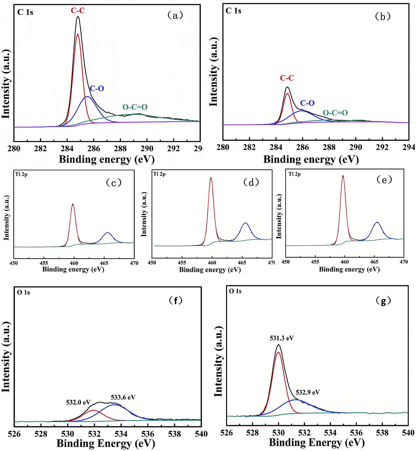 | ||
| Fig. 5 The high resolution XPS spectra of C 1s peaks of OMWCNT (a) and TiO2/MWCNT composites without heat treatment (S-Pristine) (b); the Ti 2p XPS spectra of S-Pristine (c), S-400 (d), S-500 (e); the O 1s XPS spectra of OMWCNT (f) and TiO2/MWCNT composites (g) without heat treatment (S-Pristine). | ||
In order to investigate the chemical state of C, Ti, O elements within the composites and further prove the reduction of OMWCNTs, we performed XPS measurements. The high resolution XPS data of C 1s peaks of OMWCNTs and TiO2/MWCNT composites without heat treatment (S-Pristine) were shown in Fig. 5(a) and (b). In the C 1s XPS spectrum of OMWCNTs, the peaks located at the binding energy of 285.5 eV and 288.7 eV were assigned to C–O and O–CO, which confirmed successful oxidation of MWCNTs. While in the C 1s spectrum of S-Pristine, the peak intensity of C–O decreased conspicuously, the peak of O–CO almost disappeared, verifying the reduction of OMWCNTs after the hydrothermal reaction. Fig. 5(c)–(e) showed the XPS spectra of Ti 2p for S-Pristine, S-400 and S-500, the Ti 2p3/2 and Ti 2p1/2 spin–orbital splitting photoelectrons were located at 459.8 eV and 465.5 eV, respectively, shifting toward higher binding energy compared to those of the pure bulk anatase.34 This implied that the Ti in TiO2 nanoparticles grafted on MWCNTs was in a different chemical state from that of pure anatase, which was probably due to the strong interaction between TiO2 nanoparticles and the MWCNTs and the formation of Ti–O–C bonds.
In addition, the O 1s XPS spectra of OMWCNT and TiO2/MWCNT nanocomposites were showed in Fig. 5(f) and (e). In the O 1s spectra of OMWCNTs, the peak at 532.0 eV was ascribed to C–O, CO and O–CO bonds on OMWCNTs surface, while the peak at 533.6 eV was assigned to H2O. After the hydrothermal reaction, these two peaks disappeared, while another two peaks emerged at 531.3 eV and 532.9 eV which were ascribed to Ti–O and Ti–O–C bonds in the TiO2/MWCNT nanocomposites. These results confirmed the successful reduction of OMWCNTs and integration between TiO2 and MWCNTs, and the intimate interaction between Ti, O, and C after the hydrothermal process, which was vital to the enhancement of photocatalytic activity.
Rhodamine B is one of most frequently applied organic dyes, which does much harm to the environment. Thus, in this study, relative photocatalytic activity of each photocatalyst was determined by accessing the photodegradation rate of rhodamine B under simulated sunlight irradiation. According to Sanjaya D. Perera et al.,35 the photocatalytic degradation process of pollutants could be divided into three steps—adsorption of the pollutants, adsorption of light by the photocatalyst and charge transfer reactions to create radical species to degrade the pollutants. As we have mentioned previously, the increase of specific surface area triggered by CNTs within the nanocomposites could be a contributing factor for the first step. The pollutants could only be decomposed on the catalytic surface; the absorption progress would greatly increase the concentration of the pollutants around the catalytic surface. The π–π conjugation between rhodamine B and the aromatic region of 1-D MWCNTs would certainly contribute to the enhancement of adsorbability. The introduction of CNTs extended the light absorption range which could be learned from the UV-vis absorption spectra. This meant more light energy could be utilized to generate electron–hole pairs. Based on the mechanism of photocatalysis enhancement in CNT/TiO2 nanocomposites proposed by Hoffmann et al.17 electrons excited by high-energy photons were transferred into the CNTs, and holes remained on the TiO2 to form OH˙ species, and then participated in the subsequent redox reactions. The outstanding electron accepting and trapping properties of CNTs helped retard or curb the recombination of electron–hole pairs, leading to formation of much more radical species. Given the three factors, we could expect a greatly enhanced photocatalytic activity of the TiO2/MWCNT nanocomposites when compared to pure TiO2 nanoparticles. The influence of heat treatment on the photocatalytic performance was also investigated by comparing the photocatalytic activity of samples without heat treatment to that of the heat-treated samples.
As displayed in Fig. 6, the concentrations of rhodamine B were determined from the maximum absorption (λ = 554 nm) measurements by UV-vis spectra, and were plotted as a function of irradiation time using Lamberts–Beer law. The changes of normalized concentration (C/C0) of rhodamine B with irradiation were assumed to be proportional to the normalized maximum absorbance (A/A0). It was evident that the relative photodegradation rate of TiO2/MWCNT nanocomposites exhibited a great enhancement compared to that of pure TiO2 nanoparticles. At the first 10 min, almost 80% of the total rhodamine B was decomposed by TiO2/MWCNT nanocomposites, while the amount was around 10% for pure TiO2 nanoparticles. It took 30 min to completely decompose rhodamine B for TiO2/MWCNT nanocomposites. After being irradiated for 40 min, only about 50% of Rh B was degraded by pure TiO2 nanoparticles. Pseudo-first order reaction ln(Ct/C0) = −kt was suitable for the kinetics of the photodegradation of TiO2/MWCNT nanocomposites, pure TiO2 nanoparticles, S-400 and S-500, where k, Ct and C0 were rate constant, concentration after a time t and initial concentration, respectively. The rate constant calculated for TiO2/MWCNT nanocomposites was 0.124 min−1, which was about 7 times greater than that of pure TiO2 nanoparticles (0.017 min−1). This great enhancement was attributed to the introduction of MWCNTs.
 | ||
| Fig. 6 Photocatalytic degradation of Rh B by pure TiO2, S-Pristine, S-400 and S-500 under solar simulator illumination. | ||
Further enhancement of the photocatalytic performance was observed by comparing the samples with and without heat treatment. Although degradation rates at the first 10 min did not show obvious difference, the complete degradation time for S-400, S-500 was 20 min, which were 10 min less than nanocomposites without heat treatment. It was worth mentioning that the hydrothermal progress not only yielded anatase TiO2 but also amorphous TiO2. Heat treatment at 400 °C and 500 °C transformed amorphous TiO2 to anatase, fully crystallizing the coating thereby avoiding the burnout of the MWCNTs. Besides, Ostwald ripening also occurred during the heat treatment process; smaller crystals would regrow on the larger crystals in order to achieve lower total energy,36 leading to better development of anatase TiO2 crystalline structure. The peaks of (105), (211), (116) and (220) were more evident in the XRD patterns of heat-treated samples, which meant higher crystallinity and less defects.37,38 As discussed above, higher crystallinity and fewer defects resulted in better photocatalytic performance.
Conclusion
We successfully synthesized TiO2/MWCNT nanocomposites with uniform loading through a green and effective two-step hydrothermal process. The as-prepared sample was annealed at 400 °C and 500 °C; comparative experiments were performed to investigate the relative photocatalytic activities of S-Pristine, S-400, S-500 and pure TiO2. With the introduction of MWCNTs, the composites exhibited greatly higher photocatalytic activity over pure TiO2 as a result of improved adsorbability of rhodamine B, extended light absorption range and retarded recombination of photogenerated electron–hole pairs. Moreover, after heat treatment, the photocatalyst showed further enhancement due to the better development of the anatase TiO2 crystalline structure within the nanocomposites. Our work not only verified that the performance of photocatalysts could be enhanced by the support of MWCNTs, but also developed a green way to prepare TiO2/MWCNT nanocomposites with uniform loading and high photocatalytic activity. We firmly believed that this method could be extended to other photocatalysts and sincerely hoped our work would contribute to the study of photocatalysts, thus addressing the environmental problems.Acknowledgements
This work is supported by the Natural Science Foundation of China (no. 51373096) and CAST Foundation (no. 201233). Instrumental Analysis Center of Shanghai Jiao Tong University and National Engineering Research Center for Nanotechnology were sincerely acknowledged for assisting relevant analyses.References
- H. Fu, T. Xu, S. Zhu and Y. Zhu, Environ. Sci. Technol., 2008, 42, 8064–8069 CrossRef CAS.
- Y. Wang, R. Shi, J. Lin and Y. Zhu, Energy Environ. Sci., 2011, 4, 2922–2929 CAS.
- A. Cao, Z. Liu, S. Chu, M. Wu, Z. Ye, Z. Cai, Y. Chang, S. Wang, Q. Gong and Y. Liu, Adv. Mater., 2010, 22, 103–106 CrossRef CAS PubMed.
- D. Jing and L. Guo, J. Phys. Chem. B, 2006, 110, 11139–11145 CrossRef CAS PubMed.
- M. Andersson, L. Österlund, S. Ljungstroem and A. Palmqvist, J. Phys. Chem. B, 2002, 106, 10674–10679 CrossRef CAS.
- C. Chen, W. Cai, M. Long, B. Zhou, Y. Wu, D. Wu and Y. Feng, ACS Nano, 2010, 4, 6425–6432 CrossRef CAS PubMed.
- O. Akhavan, M. Abdolahad, A. Esfandiar and M. Mohatashamifar, J. Phys. Chem. C, 2010, 114, 12955–12959 CAS.
- G. Li, D. Zhang and J. C. Yu, Chem. Mater., 2008, 20, 3983–3992 CrossRef CAS.
- S. Tokunaga, H. Kato and A. Kudo, Chem. Mater., 2001, 13, 4624–4628 CrossRef CAS.
- D. C. Hurum, K. A. Gray, T. Rajh and M. C. Thurnauer, J. Phys. Chem. B, 2005, 109, 977–980 CrossRef CAS PubMed.
- T. An, J. Chen, X. Nie, G. Li, H. Zhang, X. Liu and H. Zhao, ACS Appl. Mater. Interfaces, 2012, 4, 5988–5996 CAS.
- S. Bakardjieva, J. Subrt, V. Stengl, M. J. Dianez and M. J. Sayagues, Appl. Catal., B, 2005, 58, 193–202 CrossRef CAS PubMed.
- W. S. Wang, D. H. Wang, W. G. Qu, L. Q. Lu and A. W. Xu, J. Phys. Chem. C, 2012, 116, 19893–19901 CAS.
- M. Setvín, U. Aschauer, P. Scheiber, Y. F. Li, W. Hou, M. Schmid, A. Selloni and U. Diebold, Science, 2013, 341, 988–991 CrossRef PubMed.
- M. A. Fox and M. T. Dulay, Chem. Rev., 1993, 93, 341–357 CrossRef CAS.
- S. M. Lam, J. C. Sin, A. Z. Abdullah and A. R. Mohamed, Fullerenes, Nanotubes, Carbon Nanostruct., 2014, 22, 471–509 CrossRef CAS.
- M. R. Hoffmann, S. T. Martin, W. Choi and D. W. Bahnemann, Chem. Rev., 1995, 95, 69–96 CrossRef CAS.
- J. F. Tanguay, S. L. Suib and R. W. Coughlin, J. Catal., 1989, 117, 335–347 CrossRef CAS.
- K. Woan, G. Pyrgiotakis and W. Sigmund, Adv. Mater., 2009, 21, 2233–2239 CrossRef CAS.
- D. Eder and A. H. Windle, J. Mater. Chem., 2008, 18, 2036–2043 RSC.
- A. Kongkanand, R. Martínez Domínguez and P. V. Kamat, Nano Lett., 2007, 7, 676–680 CrossRef CAS PubMed.
- C. Y. Hsu, D. H. Lien, S. Y. Lu, C. Y. Chen, C. F. Kang, Y. L. Chueh, W. K. Hsu and J. H. He, ACS Nano, 2012, 6, 6687–6692 CrossRef CAS PubMed.
- W. Wang, P. Serp, P. Kalck and J. L. Faria, J. Mol. Catal. A: Chem., 2005, 235, 194–199 CrossRef CAS PubMed.
- K. Byrappa, A. Dayananda, C. Sajan, B. Basavalingu, M. Shayan, K. Soga and M. Yoshimura, J. Mater. Sci., 2008, 43, 2348–2355 CrossRef CAS PubMed.
- S. Muduli, W. Lee, V. Dhas, S. Mujawar, M. Dubey, K. Vijayamohanan, S.-H. Han and S. Ogale, ACS Appl. Mater. Interfaces, 2009, 1, 2030–2035 CAS.
- B. Gao, G. Z. Chen and G. Li Puma, Appl. Catal., B, 2009, 89, 503–509 CrossRef CAS PubMed.
- L. C. Jiang and W. D. Zhang, Electroanalysis, 2009, 21, 988–993 CrossRef CAS.
- S. Aryal, C. K. Kim, K. W. Kim, M. S. Khil and H. Y. Kim, Mater. Sci. Eng., C, 2008, 28, 75–79 CrossRef CAS PubMed.
- W. Fan, Q. Lai, Q. Zhang and Y. Wang, J. Phys. Chem. C, 2011, 115, 10694–10701 CAS.
- W. C. Oh, F. J. Zhang and M. L. Chen, Bull. Korean Chem. Soc., 2009, 30, 2637–2642 CrossRef CAS.
- M. Chen, F. Zhang and W. Oh, Bull. Mater. Sci., 2011, 34, 835–841 CrossRef CAS PubMed.
- N. J. Bell, Y. H. Ng, A. Du, H. Coster, S. C. Smith and R. Amal, J. Phys. Chem. C, 2011, 115, 6004–6009 CAS.
- Y. Zhang, Z. R. Tang, X. Fu and Y. J. Xu, ACS Nano, 2010, 4, 7303–7314 CrossRef CAS PubMed.
- Z. Song, J. Hrbek and R. Osgood, Nano Lett., 2005, 5, 1327–1332 CrossRef CAS.
- S. D. Perera, R. G. Mariano, K. Vu, N. Nour, O. Seitz, Y. Chabal and K. J. Balkus, ACS Catal., 2012, 2, 949–956 CrossRef CAS.
- B. Liu and H. C. Zeng, Small, 2005, 1, 566–571 CrossRef CAS PubMed.
- S. J. Tsai and S. Cheng, Catal. Today, 1997, 33, 227–237 CrossRef CAS.
- K. Tanaka, M. F. Capule and T. Hisanaga, Chem. Phys. Lett., 1991, 187, 73–76 CrossRef CAS.
| This journal is © The Royal Society of Chemistry 2015 |