Corrosion behavior of a bipolar plate of carbon–polythene composite in a vanadium redox flow battery

Huijun Liu*a, Lingxu Yangb, Qian Xub and Chuanwei Yana
aLaboratory for Corrosion and Protection, Institute of Metal Research, Chinese Academy of Sciences, 62 Wencui Road, Shenyang, 110016, P. R. China. E-mail: liuhj@imr.ac.cn; Fax: +86-24-23904551; Tel: +86-24-23904553
bSchool of Materials Science and Metallurgy, Northeastern University, Shenyang, 110819, P. R. China

Received 3rd November 2014 , Accepted 4th December 2014

First published on 4th December 2014


Abstract

The corrosion behavior of the bipolar plate of carbon–polythene composite (BPCPC) and the effect of corrosion on the mechanical strength of BPCPC in a vanadium redox flow battery are investigated by electrochemical methods. The results show that when the anodic polarization potential is above 2.0 V, the BPCPC electrode can be eroded due to the gases' (including CO2, CO, and O2) evolution. The conductive network of BPCPC can also be destroyed, which includes the oxidation of the carbon atoms both in polythene and the carbon conductive additive to R–OH + C–O–C, C[double bond, length as m-dash]O and O[double bond, length as m-dash]C–OH forms during corrosion. The damage of the conductive network leads to a decrease of mechanical strength and electroconductibility of BPCPC. Moreover, bulges and cracks are formed on the surface of BPCPC electrode exposure in the electrolyte, which may lead to battery failure because of electrolyte leakage.

1. Introduction

The vanadium redox flow battery (VRFB), as a novel electrochemical apparatus, which can transfer and store electricity effectively, has been attracting more and more attention due to its advantages such as long cycle life, deep-discharge capability, low pollution emissions, and fast response time.1–3 V(II)/V(III) and V(IV)/V(V) redox couples, which are divided into two compartments by an ion-exchange membrane, are employed as negative and positive half cells, respectively. The anodic and cathodic reactions are as follows, and standard electrode potentials are given vs. reversible hydrogen electrode (RHE):
 
image file: c4ra13697g-t1.tif(1)
 
image file: c4ra13697g-t2.tif(2)

Bipolar plates (BPs), as one of the main components of VRFB, have several functions such as separating the electrolyte of each cell, collecting the electricity and providing structural supports for the stack. Therefore, BPs should possess high electroconductivity, good mechanical stability, and corrosion resistance in the electrolyte.4–6 Among the BPs used in VRFB,6,7 the polymer based conductive composites are promising materials due to their structural stability against the acidic medium of the electrolyte and because they are flexible, cheap, and lightweight. As polymer matrix itself is an insulator, the effective way to improve the electrical conductivity of composites is to add the conductive fillers, such as graphite,8 carbon fiber,9 carbon black,10 and carbon nanotubes, to the polymer matrix.9,11 However, the poor wettability between the polymer and the carbon based filler and the agglomeration of carbon based filler will lead to poor conductive homogeneity of the polymer based conductive composites. Particularly for the VRFB-stack, the asymmetric internal resistance of battery cells caused by heterogeneous conductivity of BPs may lead to a rise of local potential and temperature in the cells, which can enhance the gases' evolution and accelerate the corrosion of the electrode.12 However, less has been reported in the previous studies on BPs corrosion. The aim of this work is to investigate the corrosion mechanism of BPCPC by electrochemical methods so as to gain some useful information for the preparation of the BPCPC electrode in VRFB.

2. Experimental

2.1. Sample preparation

The electrolyte used was a 2 mol dm−3 H2SO4 + 2 mol dm−3 VOSO4 solution at the bath temperature of 20 °C. All chemicals were of analytical grade, and de-ionized water was used for all experimental solutions. The potentiodynamic polarization curves were carried out using a PARSTAT 2273-potentiostat/galvanostat/FRA in a glass cell containing about 200 mL electrolyte. A conventional three-electrode cell was utilized, in which the reference electrode was a saturated calomel electrode (SCE), the counter electrode was a graphite plate with the dimension of 50 mm × 60 mm × 2 mm. the working electrode was BPCPC, which was composed of polythene and carbon conductive additive, supplied by ChaoYang HuaDing Energy Storage Technology Co., Ltd (China), with a working area of 0.785 cm2 exposure to the electrolyte. In addition, all of the potentials in this study are quoted with reference to SCE (i.e., 0.242 V vs. SHE) unless otherwise stated.

2.2. Characterization

The surface morphology of the BPCPC electrode before and after corrosion was characterized by XL30FEG scanning electron microscopy (SEM). High resolution X-ray photoelectron spectroscopy (HRXPS) with a resolution of 0.1 eV was obtained with ESCALAB250 XPS (Thermo VG, USA) at 5.5 × 10⁻⁸ mbar. Al-Kα (1486.6 eV) was used as the X-ray source at 15 kV of anodic voltage. Spectra were analyzed using Spectrum software (XPSPEAK41). The mechanical strength of BPCPC was measured by a pull-off test with an Electronic Universal Testing Machine Model CMT5105 controlled by a computer.

3. Results and discussion

3.1. Corrosion potential of BPCPC

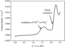
Fig. 1 displays the potentiodynamic polarization curve for the BPCPC electrode in 2 mol dm−3 H2SO4 + 2 mol dm−3 VOSO4 solution at the scan rate of 5 mV s−1. The anodic peak around 1.3 V is observed, where the primary reaction, electrochemical oxidation of VO2+ to VO2+, is controlled by both mass transport and electron transfer. However, there appears another anodic peak when the polarization potential reaches 2.0 V, according to our previous study,13 which is attributed to the gases' evolution, including CO2, CO and O2. By comparison, both of the potentials for the oxidation of VO2+ to VO2+ and gases' evolution on the BPCPC electrode are higher than those on both graphite felt and graphite electrode,14–16 which means that the corrosion resistance is higher whilst the electrochemical activity of BPCPC is lower than that of graphite felt and graphite electrode. Therefore, the investigation of the corrosion behavior of BPCPC can be carried out at the polarization potential above 2.0 V.
image file: c4ra13697g-f1.tif
Fig. 1 Potentiodynamic polarization curve for the BPCPC electrode in 2 mol dm−3 H2SO4 + 2 mol dm−3 VOSO4 solution at the scan rate of 5 mV s−1.

3.2. Corrosion mechanism of BPCPC

Fig. 2a shows the digital picture of the BPCPC electrode after polarization at 2.5 V for 6 h in 2 mol dm−3 H2SO4 + 2 mol dm−3 VOSO4 solution. A lot of bulges can be seen on the surface of the BPCPC electrode exposure to the electrolyte, which further proves the gases' evolution at 2.5 V. In addition, when the eroded BPCPC electrode is bent at ±45° twice, there appear some cracks as shown in Fig. 2b. However, when the BPCPC as received is bent at ±90° for 400 times, it has not changed. The crack suggests that the toughness of BPCPC is significantly decreased after corrosion. Moreover, the bulges and crack formed on the surface of the BPCPC electrode may lead to battery failure because of electrolyte leakage and high internal resistance of VRFB.
image file: c4ra13697g-f2.tif
Fig. 2 The digital pictures of BPCPC electrode after polarization at 2.5 V for 6 h in 2 mol dm−3 H2SO4 + 2 mol dm−3 VOSO4 solution. (a) Before bend test, (b) after bending at ±45° twice.

In order to investigate changes in the electronic surface structure and oxygen functional groups of BPCPC before and after polarization in 2 mol dm−3 H2SO4 + 2 mol dm−3 VOSO4 solution, we have chosen two representative samples for ex situ XPS analysis. The typical wide energy survey scans for the BPCPC electrode before and after potentiostatic anodic polarization at 2.5 V for 6 h are shown in Fig. 3, where the peaks at ∼284 and ∼532 eV are attributed to C1s and O1s, respectively. In addition, the peaks at ∼151 and ∼100 eV, shown in the curve (b) in Fig. 3, are attributed to Si2s and Si2p, respectively, which may be due to the SiC impurity introduced during preparation of BPCPC. Moreover, the peak at ∼198 eV is attributed to Cl2p in the form of KCl, which is introduced by reference electrode via Luggin capillary to the surface of BPCPC during anodic polarization. The peak at ∼398 eV is attributed to N1s. By comparison with spectrum a and b, the results indicate that the intensity of the O1s peak at the binding energy of ∼532 eV increases significantly after the BPCPC electrode is polarized at 2.5 V for 6 h. In addition, the O content and the O/C ratio on the BPCPC electrode after polarization reach 23.7% and 0.31, compared to 13.1% and 0.15 of the BPCPC electrode as received, respectively. This indicates that the carbon atoms are oxidized and carbon–oxygen functional groups may be introduced on the surface of the BPCPC electrode during potentiostatic anodic polarization.


image file: c4ra13697g-f3.tif
Fig. 3 XPS spectra of the BPCPC electrode before (a) and after (b) potentiostatic anodic polarization at 2.5 V for 6 h.

As we know, high energy resolution spectroscopy can enhance the information available from the abovementioned two samples. Therefore, the representative high resolution XPS C1s spectra of the BPCPC electrode before and after potentiostatic anodic polarization are fitted, and the results are shown in Fig. 4. The C1s spectra for the BPCPC electrode as received are satisfactorily fitted by means of three peaks, whose binding energies ranged from 282 to 289 eV, as shown in Fig. 4a. The main C1s peak at ∼284.3 eV indicates that the carbon is present in graphite form,17,18 which is corresponding to the carbon conductive additive in BPCPC. The positions of the C1s peaks at ∼285.3 and ∼286.6 eV are attributed to carbon in (CH2)n and C–O forms, respectively.19–21 However, the C1s spectra for the BPCPC electrode after potentiostatic anodic polarization at 2.5 V for 6 h are satisfactorily fitted by means of three new peaks of carbon in R–OH + C–O–C, C[double bond, length as m-dash]O and O[double bond, length as m-dash]C–OH forms at ∼285.0, ∼286.7, and ∼288.2 eV, respectively, in addition to the attribution of the carbon in (CH2)n forms as shown in Fig. 4b.17,22–25 In addition, the π–π* transition is detected at ∼289.6 eV.26


image file: c4ra13697g-f4.tif
Fig. 4 C1s HRXPS spectra of the BPCPC electrode before (a) and after (b) potentiostatic anodic polarization at 2.5 V for 6 h.

From the abovementioned analysis, the possible surface groups on the BPCPC electrode after polarization at 2.5 V for 6 h can be summarized and shown in Fig. 5. According to our previous study,12 the functional groups of C[double bond, length as m-dash]O and O[double bond, length as m-dash]C–OH introduced during corrosion can catalyze the formation of CO2 and CO and, therefore, accelerate the corrosion of the BPCPC electrode.


image file: c4ra13697g-f5.tif
Fig. 5 Schematic diagram for summarizing possible surface groups on the BPCPC electrode after polarization at 2.5 V for 6 h. Adapted from Stein et al.27

The SEM image for the surface of BPCPC before and after polarization at 2.5 V for 6 h in 2 mol dm−3 H2SO4 + 2 mol dm−3 VOSO4 solution is shown in Fig. 6. It can be seen that the contrast ratio of the SEM image for the area of BPCPC with and without exposure to the electrolyte is evidently different. According to the study of Ni et al.,28 the relatively dark area of the BPCPC can be ascribed to its relatively poor conductivity. Therefore, the electroconductibility of the BPCPC electrode decreases due to its corrosion.


image file: c4ra13697g-f6.tif
Fig. 6 SEM image of the surface of BPCPC without and with polarization in 2 mol dm−3 H2SO4 + 2 mol dm−3 VOSO4 solution. (a) The region for BPCPC as received, (b) the region for BPCPC polarized at 2.5 V for 6 h.

Fig. 7 shows SEM images and EDS line scan for the cross-section of the BPCPC electrode before and after polarization in 2 mol dm−3 H2SO4 + 2 mol dm−3 VOSO4 solution. From Fig. 7a and b, it can be seen that the distribution of carbon and oxygen atoms in BPCPC are homogeneous. However, delaminations are observed after corrosion of BPCPC, as shown in Fig. 7c. In addition, from Fig. 7d, it can be seen that the distribution of carbon atoms decreases significantly in the corrosion depth of BPCPC, which suggests carbon loss (including CO2 and CO evolution) during corrosion. However, the oxygen atoms increase on the cross-section of the BPCPC electrode, which may be due to the functional groups of O[double bond, length as m-dash]C–OH and C[double bond, length as m-dash]O introduced during corrosion as shown in Fig. 4.


image file: c4ra13697g-f7.tif
Fig. 7 SEM images and EDS line scan for the cross-section of the BPCPC electrode before (a) and after (b) polarization in 2 mol dm−3 H2SO4 + 2 mol dm−3 VOSO4 solution.

As we know, it is difficult to characterize the surface morphology and the structure of the BPCPC by SEM/EDX or TEM because the BPCPC undergoes high pressure during its manufacture process, and it is difficult to distinguish the carbon powder and the polythene on the surface of the BPCPC sample. In this study, the morphology and the structure of the cross-section of BPCPC is investigated before and after corrosion in order to characterize the corrosion mechanism of the BPCPC. The sample is prepared as follows: the BPCPC is first frozen in liquid nitrogen, and then broken. Finally, the cross-section of the BPCPC electrode is polarized in 2 mol dm−3 H2SO4 + 2 mol dm−3 VOSO4 solution for different times.

Fig. 8 shows the SEM images for the cross-section of the BPCPC electrode before and after polarization at 2.5 V for different times in 2 mol dm−3 H2SO4 + 2 mol dm−3 VOSO4 solution. From Fig. 8a, it can be seen that the cross-section of BPCPC is composed of the nodes and the chains, which may be representative of the carbon powder rich and polythene rich, respectively, to form the structure of a porous network. It is clear that the porous network is destroyed significantly with polarization time prolonged as shown in Fig. 8a–d. This may be due to the oxidation of carbon atoms both in the carbon powder rich and polythene rich. The most important is that from Fig. 8e, it can be seen that the chain between two nodes is broken and then formed to two new nodes, which may be polythene rich. However, by comparison with Fig. 8e, the nodes grow up and the amount of the chains decreases after polarization at 2.5 V for 12 h as shown in Fig. 8f, which may be due to the carbon loss of polythene. Therefore, the corrosion mechanism of the BPCPC electrode may include two aspects: the one is the oxidation of the carbon particles and the other is the oxidation of the polythene. These two aspects result in both the damage of the conductive network and the decrease of electroconductibility of BPCPC.


image file: c4ra13697g-f8.tif
Fig. 8 SEM images for the cross-section of the BPCPC electrode before and after polarization at 2.5 V for different times in 2 mol dm−3 H2SO4 + 2 mol dm−3 VOSO4 solution. (a and e) As received, (b and f) 12 h, (c) 24 h, (d) 48 h.

3.3. The effect of corrosion on mechanical strength of BPCPC

The relationships between the displacement and force for BPCPC before and after polarization at 2.5 V for different times in 2 mol dm−3 H2SO4 + 2 mol dm−3 VOSO4 solution are shown in Fig. 9. The results show that the strength of extension for BPCPC are 14.8, 14.0, 11.1, 5.4, and 4.5 MPa after polarization at 2.5 V for 0, 6, 12, 18, and 24 h, respectively. Moreover, the displacement is decreased during the tensile process, which suggests a decreasing of the ductility as shown in Fig. 9. Therefore, both the strength of extension and the ductility of BPCPC are decreased with the polarization time prolonged, which may be due to the broken chain of polythene and the oxidation of the carbon particles during corrosion. These results may further confirm the carbon loss of polythene, as described in Section 3.2.
image file: c4ra13697g-f9.tif
Fig. 9 The relationships between the displacement and force for BPCPC before and after polarization at 2.5 V for different times in 2 mol dm−3 H2SO4 + 2 mol dm−3 VOSO4 solution (a) as received, (b) 6 h, (c) 12 h, (d) 18 h, (e) 24 h.

4. Conclusions

The BPCPC can be eroded due to gases' (including CO2, CO and O2) evolution in 2 mol dm−3 H2SO4 + 2 mol dm−3 VOSO4 solution when the polarization potential is higher than 2.0 V. Moreover, the bulges and crack are formed on the surface of the BPCPC electrode exposure in the electrolyte, which may lead to battery failure because of electrolyte leakage.

The corrosion mechanism of the BPCPC electrode is as follows. At the micro aspect, the conductive network of BPCPC can be destroyed by the oxidation of the carbon atoms both in polythene and carbon conductive additive to R–OH + C–O–C, C[double bond, length as m-dash]O and O[double bond, length as m-dash]C–OH forms, which accelerate the corrosion of the BPCPC electrode. Moreover, in the macroscopic aspect, bulges and delamination are formed on the surface of BPCPC during corrosion because of gases' evolution, which can result in a decrease in mechanical strength and electroconductibility of BPCPC.

Therefore, it is very necessary to greatly improve the uniformity of the BPs in the VRFB-stack so as to strictly control the potential applied to the BPs further to diminish or prevent the corrosion of BPCPC. In addition, it is necessary to improve the electroconductibility of BPCPC and invent a new bipolar plate with higher corrosion resistance.

Acknowledgements

The authors acknowledge the financial support of Natural Basic Research Program of China (Grant no. 2010CB227203) and the Fundamental Research Funds for the Central Universities (Grant no. N100602009).

References

  1. E. Sum, M. Rychcik and M. Skyllas-Kazacos, J. Power Sources, 1985, 16, 85 CrossRef CAS.
  2. M. Skyllas-Kazaocs, M. H. Chakrabarti, S. A. Hajimolana, F. S. Mjalli and M. Saleem, J. Electrochem. Soc., 2011, 158, R55 CrossRef PubMed.
  3. P. Leung, X. H. Li, C. P. de León, L. Berlouis, C. T. John Low and F. C. Walsh, RSC Adv., 2012, 2, 10125 RSC.
  4. V. Haddadi-Asl, M. Kazacos and M. Skyllas-Kazacos, J. Appl. Polym. Sci., 1995, 57, 1455 CrossRef CAS.
  5. K. H. Kim, B. G. Kim and D. G. Lee, Compos. Struct., 2014, 109, 253 CrossRef PubMed.
  6. P. Qian, H. M. Zhang, J. Chen, Y. H. Wen, Q. T. Luo, Z. H. Liu, D. J. You and B. L. Yi, J. Power Sources, 2008, 175, 613 CrossRef CAS PubMed.
  7. K. H. Kim, J. Choe, S. Nam, B. G. Kim and D. G. Lee, Compos. Struct., 2015, 119, 436 CrossRef PubMed.
  8. H. C. Kuan, C. C. M. Ma, K. H. Chen and S. M. Chen, J. Power Sources, 2004, 134, 7 CrossRef CAS PubMed.
  9. R. A. Antunes, M. C. L. de Oliveira, G. Ett and V. Ett, J. Power Sources, 2011, 196, 2945 CrossRef CAS PubMed.
  10. R. Dweiri and J. Sahari, J. Power Sources, 2007, 171, 424 CrossRef CAS PubMed.
  11. B. Caglar, P. Fischer, P. Kauranen, M. Karttunen and P. Elsner, J. Power Sources, 2014, 256, 88 CrossRef CAS PubMed.
  12. H. J. Liu, Q. Xu, C. W. Yan and Y. L. Qiao, Electrochim. Acta, 2011, 56, 8783 CrossRef CAS PubMed.
  13. H. J. Liu, Q. Xu and C. W. Yan, Electrochem. Commun., 2013, 28, 58 CrossRef PubMed.
  14. W. H. Wang and X. D. Wang, Electrochim. Acta, 2007, 52, 6755 CrossRef CAS PubMed.
  15. H. J. Liu, T. T. Cai, Q. S. Song, L. X. Yang, Q. Xu and C. W. Yan, Int. J. Electrochem. Sci., 2013, 8, 2515 CAS.
  16. H. J. Liu, L. X. Yang, Q. Xu and C. W. Yan, RSC Adv., 2014, 4, 55666 RSC.
  17. A. M. Puziy, O. I. Poddubnaya, R. P. Socha, J. Gurgul and M. Wisniewski, Carbon, 2008, 46, 2113 CrossRef CAS PubMed.
  18. G. Beamson and D. Briggs, High Resolution XPS of Organic Polymers. The Scienta ESCA300 Database, John Wiley & Sons, Chichester, 1992 Search PubMed.
  19. N. Vandencasteele and F. Reniers, J. Electron Spectrosc. Relat. Phenom., 2010, 178–179, 394 CrossRef CAS PubMed.
  20. F. Garbassi, M. Morra and E. Occhiello, Polymer Surfaces from Physics to Technology, John Wiley & Sons, 1997 Search PubMed.
  21. C. Girardeaux, Y. Idrissi, J. J. Pireaux and R. Caudano, Appl. Surf. Sci., 1996, 96–98, 586 CrossRef CAS.
  22. E. Desimoni, G. I. Casella and A. M. Salvi, Surf. Interface Anal., 1990, 15, 627 CrossRef CAS.
  23. E. Desimoni, G. I. Casella and A. M. Salvi, Carbon, 1992, 30, 521 CrossRef CAS.
  24. H. Darmstadt, C. Roy and S. Kallaguine, Carbon, 1994, 32, 1399 CrossRef CAS.
  25. H. Estrade-Szwarckopf, Carbon, 2004, 42, 1713 CrossRef CAS PubMed.
  26. Y. Shao, J. Wang, R. Kou, M. Engelhard, J. Liu and Y. Wang, Electrochim. Acta, 2009, 54, 3109 CrossRef CAS PubMed.
  27. A. Stein, Z. Y. Wang and M. A. Fierke, Adv. Mater., 2009, 21, 265 CrossRef CAS.
  28. P. Ni, H. J. Li, M. Y. Yang, X. X. He, Y. Li and Z. H. Liu, Carbon, 2010, 48, 2100 CrossRef CAS PubMed.

This journal is © The Royal Society of Chemistry 2015