Electrostatically-induced trajectory switching system on a multi-inlet-multi-outlet superhydrophobic droplet guiding track

Soonil Lee a, Seulah Leea, Dayeong Kima, Jungmok Seoa, Chandreswar Mahataa, Hyunseok Hwangb, Hassan Algadiac, Saleh Al-Sayaric, Youngcheol Chaeb and Taeyoon Lee*a
aNanobio Device Laboratory, School of Electrical and Electronic Engineering, Yonsei University, 50 Yonsei-ro, Seodaemun-Gu, Seoul 120-749, Republic of Korea. E-mail: taeyoon.lee@yonsei.ac.kr
bMixed Signal IC Laboratory, School of Electrical and Electronic Engineering, Yonsei University, 50 Yonsei-ro, Seodaemun-Gu, Seoul 120-749, Republic of Korea
cPromising Center for Sensors and Electronic Devices (PCSED), Najran University, P.O. Box 1988, Najran 11001, Saudi Arabia

Received 23rd October 2014 , Accepted 8th December 2014

First published on 8th December 2014


Abstract

A multi-inlet-multi-outlet (MIMO) superhydrophobic droplet guiding track was demonstrated for water droplet manipulation using an electrostatic force-induced trajectory switching system. Without applying an external electrostatic field, the water droplet rolled along the superhydrophobic guiding track due to its extreme water repellent properties and gravitational force. By applying a DC bias to a capacitor above the guiding track, the trajectory of the water droplet can be easily controlled by the electrostatic attraction. Electrostatically-induced trajectory switching was successfully achieved when the electrostatic and gravitational forces exerted on the water droplet were properly balanced. On a MIMO superhydrophobic droplet guiding track with three inlets and four outlets, the water droplet was guided along the intended trajectory.

Introduction

Open channel microfluidic systems have been widely researched due to their considerable advantages in terms of cost, accessibility, and simplicity. These systems can be applied to various fields, including in micro reactors,1–4 water harvesting,5,6 and solution transfer.7–11 In particular, open channel microfluidic systems allow functional laboratory operations (e.g., chemical reactions, transportation) to be performed rapidly and efficiently with small-volume droplets. Conventionally, gravitational force has been used in combination with hydrophilic-patterned superhydrophobic surfaces to guide and transport water droplets. Mussel-inspired polydopamine micropatterning on superhydrophobic anodized aluminum oxide,3 hydrophilic patterned superhydrophobic Si nanowire arrays,8 high surface energy ink printing on superhydrophobic paper,4,12,13 and TiO2 nanostructures with hydrophilic micropatterning by photocatalytic lithography14 are examples of this technology. However, patterned hydrophilic microfluidic channels cause contamination of the guiding tracks and loss of water during the transportation. Recently, Mertaniemi et al. reported a water droplet guiding system using a mechanically grooved superhydrophobic copper (Cu) substrate.9 On this substrate, water droplets can roll along the grooved guiding track without losing water or contaminating the surface due to the water-repellent properties of the superhydrophobic substrate.

Among the various systems of water droplet manipulation, electric force has been used frequently due to its short response time and facile operation. Several studies on the manipulation of water droplets have been reported using electrostatic charged capacitors,15 directional electric fields generated by parallel-strip electrodes,16 or electrically-tunable wetting defects on superhydrophobic surfaces.17 Using these methods, it is possible to manipulate water droplets minutely for transportation,18 sorting,19 merging,20,21 and splitting.22 However, water droplets are exposed to the electrostatic field during the manipulation process, and should be continuously in contact with electrodes. Kawamoto et al. reported the use of electrostatic probes with dipole electrodes to manipulate a small single particle using instantaneously applied high voltage.23 Small single particles can be manipulated utilizing electrostatic probes instantaneously applied with high voltage without any mechanical contact between particles and probes. This manipulation method using electrostatic force could be advantageous for water droplet manipulation, since unnecessary mechanical contact and continuous exposure to the electrostatic field which could induce the undesired effects on the water droplet can be avoided.

In this work, we demonstrated an electrostatic-induced trajectory switching system on a high-speed multi-inlet-multi-outlet (MIMO) superhydrophobic droplet guiding track without any mechanical contact. Droplet guiding tracks were fabricated by sculpturing a shadow groove structure on a Cu plate using a computer numerical control (CNC) milling method. In order to obtain the superhydrophobic surface, Ag nanostructures were formed on the groove-structured Cu plate using electroless galvanic deposition, followed by dip-coating in 1H,1H,2H,2H-perfluorodecanethiol (PFDT). Water droplets rolled off the surface along the grooved guiding track with negligible frictional force, leaving the surface free of contaminants. Two identical capacitors, patterned back-to-back on a glass, were located above the junction of the ‘reversed Y-shaped’ groove structure on the Cu plate in order to exert electrostatic force. The electrostatic force was generated by applying a 1 kV DC bias to the capacitor. By alternatively applying the active electrostatic-induced capacitors, the trajectory of a moving water droplet could be controlled. The electrostatic-induced trajectory switching system was successfully applied to the MIMO open channel microfluidic system, which has three inlets and four outlets.

Materials and methods

Fabrication of PFDT Ag/Cu guiding track

The PFDT Ag/Cu guiding track was fabricated on a 1 mm-thick Cu plate. The starting substrate was a sculptured Cu plate with shadow grooves which had a width of 1.5 mm and a depth of 0.5 mm using a CNC mechanical milling method.9 On the sculptured Cu plate, Ag dendrites were grown by a galvanic deposition process.24 The sculptured Cu plate was cleaned with a solution mixture of NH4OH–H2O2–H2O (volume ratio of 1[thin space (1/6-em)]:[thin space (1/6-em)]1[thin space (1/6-em)]:[thin space (1/6-em)]5) at 60 °C for 10 min to remove surface organic contaminants. The copper oxide on the Cu surface was removed by dipping it into a 20% CH3COOH aqueous solution for 1 h at 40 °C. After cleaning the substrates, they were immersed into an aqueous solution of 3 mM AgNO3 at 30 °C for 30 min. Ag+ ions that were dissolved in the aqueous solution and chemically reacted with Cu atoms. Due to the difference in their ionization tendencies, Ag+ ions changed to Ag atoms when Cu atoms were converted into Cu2+ ions as follows:
 
Cu + 2AgNO3 → Cu(NO3)2 + 2Ag, (1)

Reacted Ag atoms grew with a double-roughness structure on the Cu surface. Then, the chemical superhydrophobic coating process was carried out by immersing the substrate in a 1 mM solution of PFDT dissolved in ethanol for 1 h at room temperature. After coating PFDT on the substrates, they were rinsed with ethanol to remove any residual organic reactants. The substrates were baked at 70 °C for 30 min to obtain a uniform PFDT layer.

Capacitor circuit patterning on the glass slide

To exert electrostatic force on the water droplet, a capacitor circuit was patterned on a glass slide. A 50 nm-thick Ti layer and a 300 nm-thick Cu layer were subsequently deposited on the glass slide with a patterned shadow mask using a thermal evaporator. As shown in Fig. S1, the circuit pattern consists of capacitors, electrodes, and connectors. The as-prepared PFDT Ag/Cu guiding track was located beneath the circuit-patterned glass slide at a spacing distance of 2 mm. Two capacitors of the patterned circuit were located above the left and right sides of the junction region.

Exerting electrostatic force

The as-fabricated circuit-patterned glass slide was connected with a high voltage power supply (PS325, Stanford Research Systems) to apply the DC power source. When a capacitor of the patterned circuit was biased by the DC power source with a 1 kV, strong electrostatic fields could be generated near the capacitor.

Characterization

The surface morphologies of the Ag dendrite-covered Cu plate were observed using a JEOL JSM-7001F field emission scanning electron microscope (FE-SEM). Water contact angles (CAs) were measured by a dynamic image capture camera (DSC-T30, SONY Co., Ltd.). The numerical simulation results were performed using a commercial numerical solver (COMSOL Multiphysics 4.3).

Results and discussions

In order to obtain a superhydrophobic surface for the droplet guiding track, a PFDT Ag/Cu plate was fabricated. The Ag layer of the PFDT Ag/Cu plate was formed by the growth of nanostructures using the electroless galvanic deposition method.24 The surface morphologies of the nanostructured Ag layer were changed depending on the galvanic reaction time. To observe the change in the surface wetting properties of the PFDT Ag/Cu plate, static water contact angles (CAs) and water sliding angles (SAs) were observed at different electroless galvanic deposition times. Fig. 1a shows the CAs and SAs of water droplets on the surface of the PFDT Ag/Cu plate as a function of galvanic reaction time. On the flat Cu plate coated with PFDT, the water CA was 117.3° and the water SA was greater than 90°. The water CAs moderately increased and saturated at CAs ≥ 160° when the reaction times were higher than 20 min. On the other hand, the water SA drastically decreased in between reaction times of 1 min and 5 min, followed by a gradual decrease and saturation of the SA ≈ 1°. Fig 1b shows typical top-view FE-SEM micrograph illustrating the morphology of the PFDT Ag/Cu surface with galvanic reaction for 30 minutes. Ag nanostructures were found randomly distributed over a large area and formed a double-roughness structure on the Cu plate. The Ag nanostructures were composed of a combination of clusters (ranging in size from 300 nm to 1 µm) and small Ag particles (ranging between 100 nm and 200 nm) on the Cu surface. This double-roughness structure is known to be a favorable structure for the formation of a superhydrophobic surface.25 In order to convert the Ag/Cu plate to a superhydrophobic surface, the substrate was also coated with PFDT, which has low surface tension (14.8 mN m−1). Fig. 1c is a photograph of a static water droplet on the flat surface of the PFDT Ag/Cu plate at 30 min of galvanic reaction time. The water droplet has a high CA of 160 ± 1.23° on the flat surface of the PFDT Ag/Cu plate. The PFDT Ag/Cu plate demonstrated extreme water-repellent properties.
image file: c4ra13014f-f1.tif
Fig. 1 (a) Water CAs (blue symbol along left axis) and SAs (red symbol along right axis) of 5 µL droplets on the surface of the PFDT Ag/Cu plate as a function of galvanic reaction time. (b) Typical SEM image of the top view of the PFDT Ag/Cu surface, and (c) an optical image of a 5 µL water droplet on the PFDT Ag/Cu plate (at a galvanic reaction time of 30 min). (d) Sequential photographic images of a moving water droplet (5 µL) along the PFDT Ag/Cu guiding track (the inset shows the optical image of a water droplet on the groove-structured guiding track).

Fig. 1d shows a sequence of images of a 5 µL water droplet moving along the ‘Y-shaped’ PFDT Ag/Cu guiding track. In the photographs, the locations of the water droplet are marked with black dotted arrows. Due to the highly water repellent property of the PFDT Ag/Cu surface, the water droplet successfully rolled off the surface along the curved PFDT Ag/Cu guiding track at a low tilt angle of 5°. The measured velocity of the moving water droplet on the PFDT Ag/Cu guiding track was 5.71 cm s−1 under the given tilt angle. As shown in the inset of Fig. 1d, the shape of the water droplet along the PFDT Ag/Cu guiding track was deformed to adapt to the groove structure due to gravitational and surface tension forces. The groove structure in our experiment helped the water droplet move along the guiding track as well as partially supporting the weight of the droplet by the bottom of the groove structure. The degree of deformation of water droplets induced by the edge of the groove structure affects the maximum velocity (νm) at which the water droplet is successfully guided along the curve of the guiding track.9 When the degree of deformation of water droplets as a result of gravitational force on the groove structure is increased, νm is decreased. Lower νm indicates that the droplets can be easily misguided. Thus, we use the groove structure with bottom to minimize the νm lowering effect from deformed droplet by gravitational force.

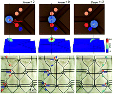
To investigate the electrostatically-induced trajectory switching system using the PFDT Ag/Cu guiding track, the systematic movements of water droplets on the guiding track were observed by alternatively applying 1 kV voltage to the capacitors patterned on the glass slide. Fig. 2a is a schematic illustration of the experimental set up of the electrostatically-induced trajectory switching system. The ‘reversed Y-shaped’ PFDT Ag/Cu guiding track was kept with a low tilt angle of 5° and electrically grounded. The substrate was located under the capacitor-patterned glass slide at a distance of 2 mm. The junction part of the PFDT Ag/Cu guiding track is emphasized with a black dotted square. The inset of Fig. 2a shows the details of the black dotted-square region. The PFDT Ag/Cu guiding track was divided into two different tracks, which were bisymmetrical at the junction. On the bottom of the glass slide, anodes and cathodes of capacitors were patterned via four 1 mm-diameter circles.


image file: c4ra13014f-f2.tif
Fig. 2 Schematic illustration of (a) experimental set up for the electrostatic-induced trajectory switching system and simulation model at the junction part of the PFDT Ag/Cu guiding track. Sequential photographic images of a moving water droplet (5 µL) on the ‘reversed Y-shaped’ PFDT Ag/Cu guiding track located under the circuit-patterned glass slide when (b) the left-side and (c) the right-side capacitors of the patterned circuit were applied with 1 kV DC bias, respectively (see the Video S1). (d) Electrostatic field distributions on the surface of water droplets at different locations on the PFDT Ag/Cu guiding track. (e) Calculated electrostatic force exerted on the water droplet (black symbol along left axis) and ddroplet (red symbol along right axis) with respect to ydroplet between 2 mm and −2 mm in the simulation model.

Fig. 2b and c show time sequence images of moving water droplets (5 µL) on the ‘reversed Y-shaped’ PFDT Ag/Cu guiding track located under the circuit-patterned glass slide and the Video S1. The droplets were moved depending on the direction of the 1 kV DC bias applied using the left-side or right-side capacitors. In these images, the locations of the moving water droplet are indicated by black dotted arrows. The anode and cathode electrodes of the patterned capacitor at 1 kV DC bias are colored with red and blue, respectively. When a water droplet was dropped from a micro-needle, it was rolled-off along the PFDT Ag/Cu guiding track until it reached the junction part of the guiding track. At the junction, an electrostatic force was exerted on the water droplet by the DC-biased capacitor. When high voltage was applied to the patterned capacitors, charges were accumulated at the edges of both anode and cathode electrodes. Due to the accumulation of charges, the strong electrostatic fields could be generated near the capacitor. Then, as the water droplet passed through the junction, it was attracted toward the DC-biased capacitor due to the electrostatic force. The trajectory of the moving water droplet was successfully changed by alternately generating electrostatic force; the direction of the droplet trajectory was switched by the position of the DC-biased capacitor. Furthermore, we also tried to control the canola oil droplet to verify the effects of electrostatic force on other liquids, however, the electrostatic attraction for sufficient water guiding was not generated. The reason could be attributed to the non-polar characteristic of the canola oil droplet. Since the polarized surface charge of the canola oil droplet by applied electrostatic field would not be generated, the electrostatic force cannot be occurred.

When the water droplet passed through the junction of the ‘reversed Y-shape’ PFDT Ag/Cu guiding track, the dynamics of electrostatic field distributions on the surface of the water droplet were analyzed using the commercial numerical solver, COMSOL Multiphysics 4.3, based on the electrostatic module. The simulation model of the junction of the ‘reversed Y-shape’ PFDT Ag/Cu guiding track was structured as seen in the inset of Fig. 2a. In this simulation, the bottom substrate and the blue-colored cathode of the capacitor were electrically grounded and the red-colored anode of the capacitor was biased with a 1 kV DC source. We assume that the water droplet on the guiding track could be approximate by a 1 mm-radius sphere. Although the shape of the water droplet was changed slightly by the groove structure of the guiding track, water droplet deformation was minimized by the support of the bottom of the track as shown in Fig. 1d. Electrowetting, which occurred as a result of the electrostatic field on the surface of the substrate, could be happened. However, the water droplet was mainly affected by electrostatic fields when it passed the junction region along the guiding track. Because of the rapid speed of the water droplet (5.71 cm s−1), this junction region was passed within 0.08 s. Furthermore, the electrostatic field on the surface of the substrate is relatively low (∼0.1 MV m−1).15 Thus, the shape change of water droplet by electrowetting in this region was negligible. The physical parameters used in the simulation are presented in Table 1. Fig. 2d represents the sequential electrostatic field distributions on the surface of the water droplet as it moved along the guiding track. The location of the water droplet on the guiding track in the simulation model was varied by decreasing the y-coordinate of the water droplet (ydroplet) from 2 mm to −2 mm. At each position, the electrostatic field on the surface of the water droplet was concentrated toward the direction of the DC-biased capacitor; however, the strength of the electrostatic fields was different at each location. When the water droplet was located at ydroplet = 2 mm, it was negligibly affected by the electrostatic fields. At ydroplet = 1 mm, weak electrostatic fields were generated near the upper surface of the water droplet. Between ydroplet = 2 mm and 0 mm, the electrostatic fields on the surface of the water droplet became strong because the distance between the water droplet and the anode of the DC-biased capacitor (ddroplet) was decreased. At ydroplet = 0 mm, ddroplet was smallest; the electrostatic fields on the surface of the water droplet were strongest, reaching a maximum value of 0.59 MV m−1. A ydroplet value of less than 0 mm suggested that electrostatic fields were weakening on the surface of the water droplet. At ydroplet = −2 mm, the electrostatic fields on the surface of the water droplet were negligible.

Table 1 Physical properties
Conductivity of Cu 5.998 × 10⁷ S m−1
Relative dielectric constant of liquid water 78
Relative dielectric constant of glass 4.2
Relative dielectric constant of air 1


The water droplet was attracted toward the DC-biased capacitor by electrostatic forces due to the concentrated electrostatic fields on the surface of the water droplet. The electrostatic force exerted on a water droplet (image file: c4ra13014f-t1.tif) can be calculated using the Maxwell stress tensor method.26 When charges were accumulated on the surface of the water droplet, electrostatic fields were exerted onto the water droplet without inducing any electrostatic fields inside the droplet. Therefore, according to the Maxwell stress tensor f, image file: c4ra13014f-t2.tif can be calculated using the numerical solver as follows:

 
image file: c4ra13014f-t3.tif(2)
 
image file: c4ra13014f-t4.tif(3)
where S is the surface area of the water droplet, ε0 is the permittivity of free space, εr is the relative permittivity of the water droplet and [E with combining right harpoon above (vector)] is the electrostatic field. [E with combining right harpoon above (vector)] is determined by the Coulomb's law and the superposition principle as shown in eqn (4).
 
image file: c4ra13014f-t5.tif(4)
where N is the number of point charges, Qi is the electric charge of the i-th point charge, and image file: c4ra13014f-t6.tif is the corresponding unit vector of ri which is the position of charge Qi with respect to the point of interest. The boundary conditions are as follows:
 
[E with combining right harpoon above (vector)] = −∇, where is the potential (5)

= 1 kV, (anode electrode)

= 0, (cathode electrode)

According to these equations, image file: c4ra13014f-t7.tif was proportional to the square of [E with combining right harpoon above (vector)] and [E with combining right harpoon above (vector)] was inversely proportional to the square of the distance between charges and the surface of water droplets. In other words, higher electrostatic force indicates a stronger electrostatic field, which could occur with decreased distance between the water droplet and the anode of the DC-biased capacitor. Fig. 2e shows the relationship between ddroplet (red symbol) and the calculated electrostatic force exerted on the water droplet (black symbol) as ydroplet is varied from 2 mm to −2 mm. While the water droplet moves from the position of ydroplet = 2 mm to ydroplet = 0 mm, the electrostatic force sharply increased with decreasing ddroplet towards the electrostatic-induced capacitor. The electrostatic force was strongest at ydroplet = 0 mm (8.21 µN) due to the smallest ddroplet. From ydroplet = 0 mm to ydroplet = −0.75 mm, the electrostatic force on the water droplet decreased as a result of increasing ddroplet. In this region, the trajectory of the water droplet could be influenced by the direction of the electrostatic force induced by the DC-biased capacitor. After the water droplet was guided toward the DC-based capacitor, it was closer to the anode of the DC-biased capacitor at ydroplet = −1 mm. The electrostatic force on the water droplet increased slightly again between ydroplet = −0.75 mm and ydroplet = −1 mm because ddroplet had decreased slightly. When the water droplet passed ydroplet = −1 mm, the electrostatic force decreased due to the increase in ddroplet again. These simulation results indicate that the electrostatic force exerted on the water droplet has a strong inversely proportional relationship with ddroplet.

To investigate the effects of DC-biased capacitors on the water droplet, the electrostatic force exerted on the water droplet was analyzed by varying the applied voltage and measuring the trajectory of the moving water droplet. When the water droplet was at the junction part of the ‘reversed Y-shaped’ PFDT Ag/Cu guiding track, the force exerted on the water droplet could be divided by two perpendicular forces on the horizontal plane: the x-directional electrostatic force (Fex) and the y-directional gravitational force (Fg). The Fg can be expressed by mg[thin space (1/6-em)]sin[thin space (1/6-em)]θSA, where m is the mass of water droplet, g is the gravitational acceleration constant, and θSA is water sliding angle. Fig. 3a shows a schematic illustration of the Fex and Fg exerted on the moving water droplet at the junction. In our experiment, since the PFDT Ag/Cu guiding track was maintained with a constant low tilt angle of 5°, the Fg was constant. On the other hand, the Fex was significantly altered according to the applied voltage. The Fex could be estimated by observing θSA, which is the critical tilt angle when the water droplet was rolled-off along the substrate.27,28 In order to estimate the Fex, a measurement system was manufactured using a line-patterned PFDT Ag/Cu guiding track and a single capacitor-patterned glass slide, as shown in the Fig. S2. In our measurement system, there are two forces that mainly affect the movement of the water droplet: the gravitational force of the water droplet at a certain sliding angle (FSA) and the Fex caused by the DC-biased capacitor. When the substrate was tilted at the θSA, the FSA becomes equivalent to the Fex. In this case, the relationship between the Fex and θSA can be expressed as follows:

 
Fex = −ρVg[thin space (1/6-em)]sin[thin space (1/6-em)]θSA, (6)
where ρ is the water density, and V is the droplet volume. At first, the θSA of a 5 µL water droplet was determined with the measurement system when the DC bias voltage applied to the capacitor was varied from 0.4 kV to 1.8 kV. According to eqn (6), the Fex was estimated using the measured θSA, 1 g cm−3 for the water density, and 9.8 m s−2 as g. In addition, the Fex, which was experimentally estimated with the measured θSA (experimental-Fex), was compared with the simulation result of the Fex calculated by the numerical solver (simulated-Fex). Fig. 3b represents the variations of the experimental-Fex fitted with the simulated-Fex with respect to the applied voltage. The results show that when the applied voltage was below 0.7 kV, the water droplet rolled-off at a θSA of ∼0°. In this case, the experimental-Fex could not be estimated since sufficient electrostatic force to control the water droplet was not applied. When the applied voltage was increased, both the experimental-Fex and simulated-Fex were substantially increased. The experimental-Fex was fitted to the simulated-Fex within a relative error of 10.1%. Furthermore, in order to investigate the aspect of electrostatic-induced trajectory switching system with various volumes of water droplets, the experimental-Fex and simulated-Fex were also observed at different volumes of water droplets (3 µL and 7 µL). Despite the difference in volume, the measured θSA of 3 µL and 7 µL water droplets were similar with the θSA of 5 µL water droplets (Fig. 3b). It could be attributed that when the FSA changed by different weight of water droplet from varying its volume, the Fex could be also equally affected by the difference of the surface areas and ddroplet of the water droplets as shown in eqn (2) and (4). Therefore, as shown in Fig. 3b, the experimental-Fex of 3 µL and 7 µL water droplets was similar to the corresponding simulated-Fex. These results indicated that our electrostatic-induced trajectory switching system can be operated in the same tilt angle condition despite the different volumes of the water droplets. Furthermore, we believe that the sub-microliter droplet can also be controlled in our system due to the almost-zero adhesion force between droplet and superhydrophobic guiding track.


image file: c4ra13014f-f3.tif
Fig. 3 (a) Schematic illustration of the Fex and Fg that affected a water droplet at the junction part of the ‘reversed Y-shaped’ PFDT Ag/Cu guiding track. (b) The experimental-Fex and simulated-Fex of water droplets of 3 µL, 5 µL, and 7 µL as a function of applied voltage. (c) Red, black, and blue symbols indicate ‘misguided’, ‘guided’, and ‘trapped’, respectively, as a function of substrate-tilt angle and applied voltage. (Red-shaded region: ‘misguided’, green-shaded region: ‘guided’, and blue-shaded region: ‘trapped’.)

To observe the critical conditions of the electrostatic-induced trajectory switching system, further experiments were conducted by altering the substrate-tilt angle and the applied voltage. For each condition, 5 µL water droplets were dropped on the PFDT Ag/Cu guiding track and a 1 kV DC bias was applied to one of the patterned capacitors. While operating the electrostatic-induced trajectory switching system, there are three possible results: ‘misguided’, ‘guided’, and ‘trapped’. ‘Misguided’ is defined as the scenario where the water droplet deviates from the intended trajectory of the PFDT Ag/Cu guiding track. Similarly, ‘guided’ is defined as when the water droplet is successfully guided on the intended trajectory. Finally, ‘trapped’ is defined as the situation where the water droplet stops at the junction of the PFDT Ag/Cu guiding track. We have included the summary of these three phenomena in Fig. 3c, which represents the experimental results as a function of substrate-tilt angle and the applied voltage. In the red region, the experiments were performed with a high substrate-tilt angle and low applied voltage (ratio of Fg and Fex, Fg/Fex > 2.93). In this case, since the water droplet was mainly dominated by the Fg, the water droplet was misguided. The large Fg could be described same as large inertial force. If the Fg is larger than Fex, the droplet is not controllable because the inertial force which is the tendency to roll off the water droplet along the guiding track regardless of the direction, would be dominant. On the other hand, in the blue region, Fex was stronger than Fg due to the low substrate-tilt angle and the high applied voltage (Fg/Fex < 1.04). Because the water droplet was mainly governed by the Fex, the water droplet was trapped on the PFDT Ag/Cu guiding track. As shown in the green region, when Fg and Fex were balanced (1.04 ≤ Fg/Fex ≤ 2.93), the water droplet was successfully guided along the intended trajectory of the PFDT Ag/Cu guiding track. Furthermore, to stably operate the electrostatic-induced trajectory switching system, the θSA and the applied voltage should be maintained below 15° and 1.4 kV, respectively.

As a proof of concept, we applied an electrostatic-induced trajectory switching system to MIMO open channel microfluidics, as shown in Fig. 4a–d and the Video S2. In this experiment, the PFDT Ag/Cu guiding track was designed with three inlets and four outlets and located under a circuit-patterned glass slide containing 12 capacitors. The guiding track and capacitor-patterned glass slide were aligned in parallel, with a distance of 2 mm between them and tilted with a low tilt angle of 5°. Fig. 4a–d show the time-sequential optical images of 5 µL water droplets moving on the PFDT Ag/Cu guiding track under a 1 kV DC bias selectively applied to the capacitors of the patterned circuit. Moving droplets were dyed orange, blue, and green at inlet 1, 2, and 3, respectively. DC-biased capacitors are emphasized and colored red at the anodes and blue at the cathodes. As shown in Fig. 4a, the orange-dyed water droplet from inlet 1 was guided to outlet 1 along the selected trajectory. The green-dyed water droplet from inlet 3 was also successfully guided to outlet 3 in Fig. 4c. Similarly, the blue-dyed water droplets from inlet 2 were guided to outlets 2 or 4, as intended, in Fig. 4b and d. We could easily control the trajectory of a moving water droplet by selectively applying DC bias on capacitors in a MIMO open channel microfluidic system.


image file: c4ra13014f-f4.tif
Fig. 4 Sequential photographic images of a 5 µL water droplet on the three inlet, four outlet PFDT Ag/Cu guiding track located under a circuit-patterned glass slide when the capacitors of the patterned circuit were selectively applied with a 1 kV DC bias to guide the water droplet along the intended trajectory: (a) from inlet 1 to outlet 1, (b) from inlet 2 to outlet 2, (3) from inlet 3 to outlet 3, and (4) from inlet 2 to outlet 4 (see the Video S2).

Conclusions

In summary, we demonstrated a facile method to fabricate a MIMO open channel microfluidic system that can switch the trajectory of a moving water droplet on a superhydrophobic guiding track using electrostatic force. The superhydrophobic droplet guiding track was obtained by growing Ag nanostructures on the track-sculptured Cu plate and coating PFDT on the Ag/Cu guiding track. Water droplets were easily rolled-off along the PFDT Ag/Cu guiding track, and the trajectory of droplets could be switched by selectively applying a DC bias to capacitors patterned on the glass slide located above the substrate. When charges were accumulated at the DC-biased capacitor, the electrostatic force was exerted on the surface of water droplet and attracted the droplet toward the capacitor at the junction of the PFDT Ag/Cu guiding track. The electrostatic-induced trajectory switching system can only successfully operate when the electrostatic force was appropriately balanced with the gravitational force of the water droplet. This electrostatic-induced trajectory switching system was applied to a MIMO superhydrophobic droplet guiding track with three inlets and four outlets. We expect that this high-speed, contamination-free, and facile droplet guiding technology has great potential to be utilized in advanced functional open-channel lab-on-a-chip applications such as in situ biomolecule detectors and micro reactors.

Note added after first publication

This article replaces the version published on 19th December 2014, in which the corresponding author was missing.

Acknowledgements

This work was supported by the Priority Research Centers Program through the National Research Foundation of Korea (NRF) funded by the Ministry of Education, Science and Technology (MEST) (2012-0006689) and by Mid-career Researcher Program through NRF grant funded by the MEST (2014R1A2A2A09053061). This work was also supported by the Industrial strategic technology development program (10041041, development of nonvacuum and nonlithography based 5 µm width Cu interconnect technology for TFT backplane) funded by the Ministry of Knowledge Economy (MKE, Korea). In addition, the authors would like to acknowledge the support of the Ministry of Higher Education, Kingdom of Saudi Arabia for supporting this research through a grant (PCSED-009-14) under the Promising Centre for Sensors and Electronic Devices (PCSED) at Najran University, Kingdom of Saudi Arabia. We thank the Tanaka Kikinzoku Kogyo K. K. for comments on the usage of silver.

Notes and references

  1. M. Washizu, IEEE Trans. Ind. Appl., 1998, 34, 732–737 CrossRef CAS.
  2. A. C. Hatch, J. S. Fisher, S. L. Pentoney, D. L. Yang and A. P. Lee, Lab Chip, 2011, 11, 2509–2517 RSC.
  3. I. You, S. M. Kang, S. Lee, Y. O. Cho, J. B. Kim, S. B. Lee, Y. S. Nam and H. Lee, Angew. Chem., Int. Ed., 2012, 51, 6126–6130 CrossRef CAS PubMed.
  4. W. Dungchai, O. Chailapakul and C. S. Henry, Anal. Chem., 2009, 81, 5821–5826 CrossRef CAS PubMed.
  5. D. Belder, Angew. Chem., Int. Ed., 2005, 44, 3521–3522 CrossRef CAS PubMed.
  6. A. R. Parker and C. R. Lawrence, Nature, 2001, 414, 33–34 CrossRef CAS PubMed.
  7. S. K. Cho, H. Moon and K. Chang-Jin, J. Microelectromech. Syst., 2003, 12, 70–80 CrossRef.
  8. J. Seo, S. Lee, J. Lee and T. Lee, ACS Appl. Mater. Interfaces, 2011, 3, 4722–4729 CAS.
  9. H. Mertaniemi, V. Jokinen, L. Sainiemi, S. Franssila, A. Marmur, O. Ikkala and R. H. Ras, Adv. Mater., 2011, 23, 2911–2914 CrossRef CAS PubMed.
  10. H. Gau, S. Herminghaus, P. Lenz and R. Lipowsky, Science, 1999, 283, 46–49 CrossRef CAS.
  11. L. Hong and T. Pan, Microfluid. Nanofluid., 2011, 10, 991–997 CrossRef CAS.
  12. Z. Nie, C. A. Nijhuis, J. Gong, X. Chen, A. Kumachev, A. W. Martinez, M. Narovlyansky and G. M. Whitesides, Lab Chip, 2010, 10, 477–483 RSC.
  13. M. Elsharkawy, T. M. Schutzius and C. M. Megaridis, Lab Chip, 2014, 14, 1168–1175 RSC.
  14. X. Zhang, M. Jin, Z. Liu, S. Nishimoto, H. Saito, T. Murakami and A. Fujishima, Langmuir, 2006, 22, 9477–9479 CrossRef CAS PubMed.
  15. H. Zhou and S. Yao, Lab Chip, 2013, 13, 962–969 RSC.
  16. M. Gunji and M. Washizu, J. Phys. D: Appl. Phys., 2005, 38, 2417 CrossRef CAS.
  17. D. t. Mannetje, S. Ghosh, R. Lagraauw, S. Otten, A. Pit, C. Berendsen, J. Zeegers, D. van den Ende and F. Mugele, Nat. Commun., 2014, 5, 3559 Search PubMed.
  18. Y. Zhang and T. H. Wang, Adv. Mater., 2013, 25, 2903–2908 CrossRef CAS PubMed.
  19. L. W. Wang, C. Yang and C. M. Li, Lab Chip, 2009, 9, 1504–1506 RSC.
  20. L. H. Hung, K. M. Choi, W. Y. Tseng, Y. C. Tan, K. J. Shea and A. P. Lee, Lab Chip, 2006, 6, 174–178 RSC.
  21. X. Niu, S. Gulati, J. B. Edel and A. J. deMello, Lab Chip, 2008, 8, 1837–1841 RSC.
  22. D. R. Link, S. L. Anna, D. A. Weitz and H. A. Stone, Phys. Rev. Lett., 2004, 92, 054503 CrossRef CAS.
  23. H. Kawamoto, J. Electrost., 2009, 67, 850–863 CrossRef PubMed.
  24. I. A. Larmour, S. E. Bell and G. C. Saunders, Angew. Chem., Int. Ed., 2007, 46, 1710–1712 CrossRef CAS PubMed.
  25. N. A. Patankar, Langmuir, 2004, 20, 8209–8213 CrossRef CAS PubMed.
  26. S. Y. Park, S. Kalim, C. Callahan, M. A. Teitell and E. P. Chiou, Lab Chip, 2009, 9, 3228–3235 RSC.
  27. J. Seo, S. Lee, H. Han, H. B. Jung, J. Hong, G. Song, S. M. Cho, C. Park, W. Lee and T. Lee, Adv. Mater., 2013, 25, 4139–4144 CrossRef CAS PubMed.
  28. J. Seo, J. S. Lee, K. Lee, D. Kim, K. Yang, S. Shin, C. Mahata, H. B. Jung, W. Lee, S. W. Cho and T. Lee, Adv. Mater., 2014, 26, 7043–7050 CAS.

Footnotes

Electronic supplementary information (ESI) available. See DOI: 10.1039/c4ra13014f
These authors equally contributed to this work.

This journal is © The Royal Society of Chemistry 2015
Click here to see how this site uses Cookies. View our privacy policy here.