Morphological patterns of a growing biological tube in a confined environment with contacting boundary

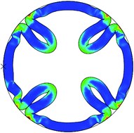
Mir Jalil Razavi and Xianqiao Wang*
College of Engineering, University of Georgia, Athens, GA 30602, USA. E-mail: xqwang@uga.edu

Received 20th October 2014 , Accepted 19th December 2014

First published on 19th December 2014


Abstract

Growing soft tissue with a confined boundary is accompanied by a large strain and stress which lead to instability and the formation of surface wrinkling, folding or creasing. This paper presents the morphological evolution of the growth of a biological tube composed of a neo-Hookean hyperelastic material within a confined environment. Critical growth ratios for the triggering of creases or detachment from the contacting boundary have been investigated both analytically and numerically. Results show that compressive residual stresses induced by confined growth of the tubular tissue can lead to a variety of surface folding patterns which strongly depend on the thickness of the tube. In a thick tube creases begin to form at the inner surface of the tube and in a thin tube the structure detaches from the confining wall. Between these two extremes there is a transitional area wherein the tube starts to crease at first and then detaches from the confining wall. Further modeling reveals that a gap between the tube and the confinement can tune the shape evolution of the growing biological tube. These findings may provide some fundamental understanding to growth modeling of complicated biological phenomena such as cortical folding of the brain and the growth of solid tumors.

1 Introduction

Growth of soft biological tissues is an important yet highly complex process that has undeniable influence both in the normal development of biological tissues and in various pathological conditions. Irrespective of growth type, it has been accepted for a long time that growth may generate residual stress in tissues.1 Residual stress has been observed in growing soft biological tissues and is believed to play a crucial role in morphogenesis and regulation of the material properties of biological systems.2–5 This stress is essential in preserving the integrity of biological structures by inhibiting the body tissue from overlapping with itself and/or external boundaries, or by creating cavities.3,6–8 Hence, general deformation in biological tissue is related to both growth and elasticity in the material.3,6,9–11 It has been proven that, as the compressive residual stress exceeds a critical value, by releasing potential energy the tissue buckles into a new configuration.8,12–17 Beyond the critical condition, three common types of morphological instability can be observed: wrinkling, folding, and creasing. Wrinkling refers to wavy surface patterns which are achieved by appropriate compression of a stiff layer on a soft compliant substrate. Ridges and valleys are detectable in this kind of instability.13,14,18–21 Folds are post-buckling evolutions of wrinkled surfaces and can be created by further compression of wrinkled surface until the formation of localized, deep surface valleys.22,23 In contrast, in soft material without a hard skin compression beyond the critical value leads to the formation of creases with sharp edges. One of the main characteristics of creases is the development of self-contact phenomenon after instability.24–27 The various shapes of plants, rippling of leaves, wrinkling of mucosa, corrugation of skin, fingerprint patterns, swell induced surface creasing of hydrogels and cortical folding of the brain are all the result of growth and instability in the constituent soft materials.13,28–31 Swell induced instability of the hydrogels is an interesting phenomenon because it has been controllably used to mimic the growth of soft tissues.32,33 A hydrogel swells considerably when absorbing a large amount of solvent (e.g., water). However, it is yet a debatable question which and how accurately chemical or physical hydrogels can mimic growth of biological tissues.34 Recent studies have showed that controllable surface patterns by chemical modification of molecular structures can be generated near the surface.35,36 Despite of diversity between the soft tissues, remodeling and morphological evolution is an important contributor to the healthy behavior of soft biological tissues like the artery, heart, brain and airway. Inappropriate growth processes may cause pathological disorders in organs such as asthma, mucosal inflammation, gastroenteritis, chronic bronchitis, autism and tumor invasion.5,10,11,13,37,38 Many studies have been done to present analytical models for growth and bifurcation to complement knowledge about the mechanisms of growing living tissues, e.g. Rodriguez et al.6 proposed a general continuum formulation for finite volumetric growth in soft elastic tissues with the deformation gradient tensor of the tissue described as the multiplication of the elastic and growth parts. Ben Amar et al.3 adopted incremental deformation theory to include growth effects and showed its application to a growing spherical shell under external pressure. Bo li et al.13,39 presented a linear stability analysis to investigate critical conditions and characteristic buckling patterns. The results indicate that the wrinkling mode is sensitive to the geometry as well as the properties of tissues. Jin et al.,27 by application of criteria for the starting of creases, found critical growth ratios for a tube growing inside a rigid shell and a growing shell on a rigid core. Ciarletta et al.4 proposed a variational method that gives a straightforward derivation of the linear stability analysis for bifurcation analysis. Dunlop et al.40 developed a general thermodynamically theoretical model for tissue growth and applied it for a simple geometry as isotropically elastic tissue growing inside a circular pore. The study extended the model in order to couple tissue growth to the presence of a surface stress.41 Rumpler et al.42 showed that geometry had effect on the tissue growth and as a result, local curvature strongly influenced the tissue growth rate. Beside these analytical models, numerical analyses and especially finite element models are valuable solutions when there is not any exact formulation for the buckling and post-buckling analysis.12–14,16,30 Analytical and numerical results of these studies reveal that beyond the critical growth ratio the system tends to be destabilized and prefers to release its potential energy by developing wrinkles and creases. Balance between geometry and material behavior of layer/layers dictates the number of wrinkles or creases.4,13,24,27 Although significant progress has been made in recent years on the modeling of morphological instability in soft matter, there remain plenty of interesting problems that needs additional experimental and theoretical investigation.15 In this study we will focus on soft material growth in a confined environment, especially with contact properties between boundaries, as many growing tissues are in contact with other tissues or consist of several layers with different material properties; thus, the existence of confinement has a remarkable effect on the stress distribution of the structure, triggering instability and remodeling processes. Many living tissues are growing in confined area; e.g. wrinkling and folding of mucosa,13,37,39 wrinkling of solid tumors34 and folding of the cortical layer of brain5,30 are all results of growth and instability in confined conditions. Study of confined growth with the contacting boundaries is a core issue due to its great impact on clarifying tumor and brain growth. Tumors deform the surrounding tissue due to the stresses imposed on the environment, and the environment in turn alters the tumor growth dynamics. Tumor growth inhibition depends on the stiffness of the surrounding environment. In an in vitro setting, this corresponds to the stiffness of the agarose gel, and in vivo this corresponds to the stiffness of the extracellular matrix environment.43 Experimental results highlight that geometric confinement alters the shape and growth dynamics of a developing tumor. In brain growth, the mechanical constraint of the skull regulates the cortical folding process. Cortical development with the skull as a constraint is much more convoluted than without.44 On the other hand, a general model of tumor or brain growth accounting for geometric confinement effects on the size and shape of a growing tumor or developing brain5,45 is lacking and remains to be further exploited. Therefore, study and research in this area is worthy of pursuit and may open new windows to the treatment and therapy of severe disorders. In this paper, in contrast to other studies, we will discuss the growth of single layer tubular soft tissue in a confined boundary with contact properties between tissue and environment. Critical growth ratios, both analytical and numerical, will be determined for the formation of creases or detachment of tissue from the contact boundary. In a special case the effect of gap magnitude between the outer layer of tube and confinement will be evaluated.

2 Theoretical investigation

2.1 Basic equations for growth model

Due to growth, the final state of the system will be different from the initial one. Theoretical models have attempted to relate the growth ratio to the deformation and stress field. Any point X in the reference state will be mapped by transformation to the final one, x, in the current state. For modeling volumetric growth we consider the most famous theory, namely, multiplicative decomposition of deformation gradient.6 In this theory the deformation gradient, F(X), is decomposed to growth tensor G(X), indicating the addition of materials, and elastic deformation tensor A(X) describing pure deformation resulting from stress. The growth tensor maps the stress-free reference configuration to a grown stress-free state, then the elastic deformation tensor maps the grown state to a stressed and final current state.6 Deformation gradient F maps the tissue from the stress free state before the growth to the stressed state after the growth.
 
F = A·G (1)
where image file: c4ra12795a-t1.tif. While both G and A tensors may be incompatible deformations, their multiplication, F, should be a compatible deformation.6 In general, the elastic deformation of living soft tissues yields little volume change, therefore, the nonlinear response of these materials can be described by an isotropic incompressible hyperelastic material. The incompressibility implies the determinant of the elastic deformation tensor should be equal to unit, det A = 1. In general, the growth tensor depends on the stress state, deformation, and some other factors. For simplicity, we assume the growth process with a known spatial distribution, insinuating that all the biological information is independent of stresses.3

Many biological soft tissues can be modeled by a hyperelastic material with a strain energy function W(A). The Cauchy stress σ is related to the strain energy function by3

 
image file: c4ra12795a-t2.tif(2)
where p is the hydrostatic pressure and I is a second-order unit vector. In the absence of any body force, mechanical equilibrium imposes
 
divσ = 0 (3)
where “div” stands for the divergence operator in the current configuration. There are several proposed material behaviors for hyperelastic material;46 here a simple and common model, isotropic nonlinear neo-Hookean, is implemented.
 
image file: c4ra12795a-t3.tif(4)
where μ is the shear modulus and λr, λθ and λz are the radial, circumferential and axial principal stretches, respectively.

2.2 Residual stress induced by growth

Consider a tubular soft tissue grown inside a rigid confinement. The outer layer of tissue is in contact with the boundary as seen in Fig. 1.
image file: c4ra12795a-f1.tif
Fig. 1 Initial and current states of a growing tube inside a confined boundary.

According to Fig. 1, the inside and outside radii of the tube are A and B, and the thickness is BA. The initial and undeformed configuration for the tube is defined by X = (R, Θ, Z)

 
ARB, 0 ≤ Θ ≤ 2π, 0 ≤ ZL, (5)
where R, Θ and Z are cylindrical coordinates in the initial state. L is longitudinal length of the tube. Due to growth, the tube will deform axisymmetrically before the occurrence of instability in the system. The new and current configuration after growth is defined by x = (r, θ, l)
 
arb, 0 ≤ θ ≤ 2π, 0 ≤ zl, (6)
where r, θ and z are cylindrical coordinates in the deformed state and l is deformed axial length. In the case of axisymmetric and plane-strain deformation, the deformation field after growth is just function of radius, r = r(R). So, circumferential and longitudinal coordinates in both deformed and undeformed states will be the same. For eliminating longitudinal effect and studying in-plane bifurcation the plane-strain assumption has been considered.

By application of the deformation gradient in cylindrical coordinates for this specific case, F(X) can be determined

 
image file: c4ra12795a-t4.tif(7)

On the other hand, the growth tensor G is

 
image file: c4ra12795a-t5.tif(8)
where gr and gθ are radial and circumferential growth ratios, which gi > 1 is for growth and 0 < gi < 1 represents atrophy. In plane-strain condition without deformation and growth in axial direction, gz is considered as unit.

From eqn (1) the elastic deformation tensor can be extracted

 
image file: c4ra12795a-t6.tif(9)
which shows
 
image file: c4ra12795a-t7.tif(10)

With incompressibility constraint detA = 1

 
image file: c4ra12795a-t8.tif(11)

As isotropic growth of soft tissue is interpreted in this paper, hereafter gr = gθ = g. So, for isotropic growth

 
image file: c4ra12795a-t9.tif(12)

Integration of eqn (12) gives

 
r2a2 = g2(R2A2) for ARB (13)

This shows the deformed field relates to the growth ratio and the initial state. Before instability, the outer layer of the tube is in contact with a stiff boundary, so b = B. From this constraint “a”, inner radius of tube after deformation, is determined and final equation for the deformed state is

 
r2 = B2 + g2(R2B2) for ARB (14)

For preventing self-contact effects in the inner radius, the isotropic growth ratio should satisfy

 
image file: c4ra12795a-t10.tif(15)

Based on eqn (2) and (4) the Cauchy stress components are derived as

 
σrr = μλr2p, σθθ = μλθ2p (16)

The equilibrium equation, eqn (3), is derived as

 
image file: c4ra12795a-t11.tif(17)

With eqn (10), (14), (16) and (17), the stress distribution is derived to be

 
image file: c4ra12795a-t12.tif(18)
 
image file: c4ra12795a-t13.tif(19)

In Fig. 2 the normalized radial and circumferential Cauchy stresses, image file: c4ra12795a-t14.tif, have been sketched for growth ratio g = 1.15 and A/B = 0.6.


image file: c4ra12795a-f2.tif
Fig. 2 Normalized stress distribution in radial and circumferential directions, g = 1.15 and A/B = 0.6.

Fig. 2 shows that the circumferential stress in the inner radius of tube is greater than other places. This stress as mentioned in the introduction part may have an important effect on the onset of instability. Circumferential stress in the inner radius is also sensitive to the thickness of the tube. In a tube with high thickness (when ratio of inner radius to outer radius is small) increasing by a small amount the growth ratio, circumferential compressive stress increases rapidly in inner surface in comparison to a thin tube, as seen in Fig. 3. A thick tube, A/B = 0.6, is more sensitive to the growth ratio and by slightly increasing the growth ratio, circumferential compressive stress is increased dramatically, In contrast, in a thin tube, A/B = 0.9, a higher growth ratio is needed to create large compressive stress in the inner surface. This observation is based on analytical formulation and without instability consideration; hence, instability may change this trend beyond the critical growth ratio.


image file: c4ra12795a-f3.tif
Fig. 3 Normalized circumferential stress in the inner radius for different growth ratios.

3 Instability analysis

With a large growth ratio, it is observed that circumferential stress in the inner surface of the tube will be increased. This stress may trigger instability and remodeling in the tube. A linear wrinkling analysis for this system with a fixed boundary condition in the outer layer reveals that wrinkles can be formed beyond a specific growth ratio. The critical growth ratio for starting instability and number of wrinkles depends on the thickness of the tube.39 Another attempt shows that creases form in the inner side of the tube below the critical growth ratio to initiate wrinkling. In other words, the critical growth ratio for formation of creases is less than the critical growth ratio for formation of wrinkles.27 The result for crease formation is based on the analysis of finite-element calculation for incompressible neo-Hookean material. The critical condition for onset of crease formation in the circumferential direction (normal to radial direction) is that the ratio of principal stretch in the radial direction to the circumferential direction in the inner radius should be more than 2.4.26
 
image file: c4ra12795a-t15.tif(20)
where, as indicated before, λr and λθ are the principal stretches in the radial and circumferential directions.

By applying this equation, the critical growth ratio for isotropic growth in radial and circumferential direction and with plane-strain condition (λz = 1 and gz = 1) can be derived.

From eqn (10), (12) and (14) in the inner radius of tube

 
image file: c4ra12795a-t16.tif(21)
or
 
image file: c4ra12795a-t17.tif(22)

It is clear that the critical growth ratio depends on the initial configuration and thickness of the tube. Fig. 4 plots the critical growth ratio, gc, for the onset of creases as a function of A/B.


image file: c4ra12795a-f4.tif
Fig. 4 Critical growth ratio for starting creases.

Due to the symmetry in the system there is no slip between the outer layer of the tube and the stiff confinement. By growth of the tube, confinement pushes the outer layer and creases start to form from the inner radius. As it can be seen from Fig. 4, in thick tube the critical growth ratio for starting instability is low and with a small amount of growth creases can be developed in the inner surface of the tube. In contrast, in tube with small thickness, for starting instability higher growth ratios should be applied. This result shows that in the same condition thin tubes are more stable than thick ones. It is worthwhile to mention these critical growth ratios have been derived based on the assumption that there is not any detachment of the outer layer of the tube from the boundary. Since there is contact property between the outer layer and confinement in some cases, detachment may change the instability form and lead to a different final configuration. This phenomenon will be further demonstrated by application of finite element modeling in the following section.

4 Finite element model

4.1 Transition from crease to detachment

For the evaluation of tube growth, formation of creases, and detaching phenomenon several non-linear finite element models have been carried out in the commercial finite element software. The plane-strain models with neo-Hookean material behavior are performed and growth is simulated with thermal expansion.12,27 A fixed discrete rigid circle as a confinement is modeled around the outer surface of the tube and a frictionless contact relation is employed. The inner and outer surfaces of the tube are allowed to self-contact, as the inner surface after creasing and the outer surface after detaching will be in a self-contact condition. Fig. 5 shows the initial and deformed state of tube after a certain amount of growth inside the confined boundary, and indicates that stress concentration is higher in the inner surface, which is consistent with the analytical results.
image file: c4ra12795a-f5.tif
Fig. 5 (a) Initial state and (b) deformed state and Von Mises stress counter of growing tube, A/B = 0.6 and g = 1.034.

In the plane-strain isotropic growth and with the condition of incompressibility, because expansion in the longitudinal direction is neglected, the growth ratio can be defined as the ratio of deformed area to initial area. From the growth tensor in eqn (8) the isotropic growth ratio is

 
image file: c4ra12795a-t18.tif(23)
where S is defined as the deformed area and S0 is the initial area. If there is not any confinement the tube will expand freely, but stiff confinement prevents growth of the tube on the outer surface and causes residual stress. Fig. 6 compares the deformed inner radius “aversus growth ratio between the theoretical analysis in eqn (13) and the finite element model for A/B = 0.6. From the figure it is clear that theory and finite element model result are in very good agreement. Since in derivation of eqn (14) (deformation field) instability and crease formation has not been considered, by continuation of growth the inner surface analytically keeps its circular pattern, but in the finite element models beyond the critical growth ratio the tube starts to form creases and buckles towards an irregular shape.


image file: c4ra12795a-f6.tif
Fig. 6 Comparison between theoretical results and finite element analysis for deformed inner radius, A/B = 0.6.

When the growth ratio increases stepwise beyond the critical value, the system will lose stability and begin to form creases in the inner surface of thick tubes or detach from the boundary and snap inwards in thin tubes. There should be a transition area between the two distinct instability patterns. The starting point for either crease formation or detachment is the critical growth ratio. In Fig. 7, different growth patterns of a thick tube in a confined boundary can be seen. After the critical growth ratio the system loses stability, and creases in order to release a portion of its elastic energy and becomes more stable.


image file: c4ra12795a-f7.tif
Fig. 7 Evolution of expansion and crease formation induced by the growth, A/B = 0.6. (a) g = 1 (b) g = 1.122 (c) g = 1.189 (d) g = 1.234 (e) g = 1.246.

Since the thickness is high, the outer surface does not lose contact from the stiff boundary and creases develop only in the inner surface of tube. In contrast, in low thickness tubes, before crease formation in the inner surface the tube detaches from the stiff boundary and buckles completely towards the inside. Similar phenomena have been seen and modeled using confined elastic rings or confined thin-walled cylinders in structural engineering.47–49 Fig. 8 shows expansion and buckling of a thin tube which after the critical point loses contact with the confinement. According to eqn (22), for thin tubes a higher growth ratio is needed to start creasing, so thin tubes store more elastic energy and hence before starting to crease they lose contact with the confinement surface and snap inwards to release energy. After the critical growth ratio, the tube loses contact and buckles towards the inside, and eventually starts to fill the area of confinement with further growth.


image file: c4ra12795a-f8.tif
Fig. 8 Evolution of expansion and detaching phenomenon induced by the growth, Von Mises stress distribution, A/B = 0.9. (a) g = 1 (b) g = 1.332 (c) g = 1.520 (d) g = 1.825 (e) g = 2.271.

It can be anticipated that there is a transition area wherein the tube at first starts to develop creases in the inner surface and after further growth loses contact with the boundary with snapping inwards. Fig. 9 depicts a transition form from creasing to detaching.


image file: c4ra12795a-f9.tif
Fig. 9 Evolution of expansion, crease formation and detaching induced by the growth, A/B = 0.75. (a) g = 1 (b) g = 1.214 (c) g = 1.307 (d) g = 1.383 (e) g = 1.512.

Under contact boundary conditions different patterns of instability of the soft tissue due to growth may arise in contrast to fixed boundary.27,39 In contact boundary configurations, creasing or detaching or both of them can be noticed in models. We can categorize this morphological evolution in the three phases: creasing, transition (crease-detach) and complete detaching. In Fig. 10, critical growth ratios from the theoretical analysis (Fig. 4) and finite elements models have been compared. It should be mentioned that here the theoretical part is based on the fixed boundary assumption. As marked in the figure, there are three phases: A for the thicknesses where only creases occur, B for the transition area where at first creases form in inner surface and then detachment happens, and C for detachment. In the transition phase (B) the lower critical growth ratio is for crease starting and the higher one is for detaching. This can be explained: since at the starting point the thickness is larger, a larger growth ratio is needed to detach the system from the boundary.


image file: c4ra12795a-f10.tif
Fig. 10 Phase diagram of critical growth ratio under different thicknesses.

4.2 Gap effects

Current studies have concluded that fixed and contact boundaries exert different effects on the morphological changes of a confined tissue tube. The critical growth ratios for creasing or detachment sensitively depend on the geometrical parameters. Another effective parameter which may cause a change in the instability behavior of the system is an existing gap between the outer surface of the tube and the confinement.49 In the previous models this gap is considered as zero and the tube and confinement boundary are in close contact with each other. In this section we investigate the gap effect on the stability of a confined tube in only one initial configuration, A/B = 0.6. The gap is showed by δ and for eliminating magnitude effects we consider it in dimensionless form δ/h, such that h is the thickness of tube (h = BA), see Fig. 11.
image file: c4ra12795a-f11.tif
Fig. 11 Initial configuration of tubular tissue, A/B = 0.6 with existing gap (δ).

According to Fig. 7, in contact boundary without a gap the tube just forms creases in the inside surface and does not lose contact from the confinement. Fig. 12 illustrates how the gap may change the critical growth ratios and final configuration of destabilized system. In contrast to close contact behavior, the existence of a gap changes the instability form and may cause detaching phenomenon. With small gaps the tube just forms creases in the inside surface and the outer surface will be in close contact to the confinement. By increasing the gap, after formation of creases and further growth, the tube loses contact from the confinement and detaches. This trend holds for gaps that are comparable to the thickness. For large gaps (greater than the thickness) again we will see only creases in the inside surface and no detachment from the confinement.


image file: c4ra12795a-f12.tif
Fig. 12 Critical growth ratio of the tubular tissue versus the dimensionless gap for A/B = 0.6.

For small gaps, after a slight growth, contact between the outer surface and confinement occurs where the state of the system is similar to a close contact situation and only creasing on the inside surface can be seen. But in larger gaps, when magnitude of the gap is comparable with thickness of the tube, balance between the gap magnitude and thickness dictates instability forms. The tube at first develops creases and then detaches from the confinement. In gaps larger than the tube thickness, after contact the tube starts to form creases in the inner surface and the grown thickness prevents the tube from detachment. Fig. 13 shows growth and instability for a sample of models with an initial gap δ = 0.8h.


image file: c4ra12795a-f13.tif
Fig. 13 Growth and morphological evolution of tube with initial gap (A/B = 0.6, δ/h = 0.8). (a) g = 1 (b) g = 1.247 (c) g = 1.504 (d) g = 1.659 (e) g = 1.824.

These results have shown that an initial gap has a crucial effect on triggering instabilities and stabilizing the final configuration of the system. In a single layer tube, the thickness of the tube and magnitude of the initial gap are the most important parameters that control the morphogenesis of the soft confined tube. Since the single layer tube has been considered as an isotropic hyperelastic material, the magnitude of the shear modulus has no effect on the instability and crease formation. In contrast, as has been studied previously, the shear modulus ratio for double or multilayer systems is quite an important parameter for the starting and developing of buckling or postbuckling,12–14 which will be explored in future work dealing with a confined environment.

5 Summary and outlook

In this paper, we have explored growth induced morphological instability of a soft tube in a confined boundary. Results show that for a growing soft tube restricted with a stiff boundary, dependent on the tube thickness and the initial gap with the boundary, multiple instability patterns may be seen in the structure. Analytical and numerical models revealed that by growth and expansion of a tube, higher compressive stress is observed in the inner surface of the tube which is a crucial parameter in triggering instability and crease formation. In tubes with high thickness and a small growth ratio, compressive stress arises in high levels and creases start to form to release strain energy. In contrast, when tube thickness is small in compare to the mean radius of the tube, a higher growth ratio is needed to destabilize the structure and in this situation the tube begins to detach from the boundary and buckle towards the interior. Between large and small tube thicknesses there is a transition area where the tube at first starts to develop creases in the inner surface and with further growth detaches from the stiff boundary. Another parameter which has a notable effect on the morphological evolution is the existence and size of a gap between the outer layer of the tube and the confined boundary. Results for a special case show that dependent on the ratio of gap to tube thickness, all multiple bifurcation patterns can happen.

These preliminary results are suitable to the modeling of confined growth of soft biological materials, e.g. brain and tumors. It has proven that mechanical constraints the brain skull exerts influence the cortical folding process.50 Recently, it has been showed that this kind of modeling can explain and predict some developing brain abnormalities.51,52 These studies showed that the thickness ratio of cortex to subcortex in developing brain is a very important parameter just as thickness of a growing tube is a main parameter to the determination of evolution path. Many of solid tumors create a layered structure during their avascular evolution. For more expansion, some tumors such as melanoma or glioblastoma lose their initial symmetries to trespass the encompassing tissues53 which experimental study for shape transition of these tumors showed that formation of creases in outer layer is highly dependent on the thickness ratio.54 In other words, these biological tissues are growing in confined environments and elastic or stiff boundaries can change their shape and performance and in some special cases lead to disorders. Therefore, as the continuation of this work, it is worth to study the effect of confinement elasticity on the morphological evolution of a growing model. We can expect that elasticity of the surrounding area will have a great influence on the morphogenesis of the growing tissue. As another application, it is possible to apply the present analysis, with some modifications, to model the swell of hydrogels which is accompanied by diffusion or chemical process. For example, an extra term such as concentration of solvent molecules has been introduced into Helmholtz free energy density55 in addition to deformation gradient tensor. Therefore, the nominal stress is a function of deformation gradient and concentration of solvent.56

No research, however, provides a perfect answer, with this work being no exception to the rule. It is worthwhile to mention that in application of theoretical and computational models there are some simplifications and assumptions which impose limitations to our results. For example, a simple neo-Hookean hyperelastic material was considered, while in the reality, biological or soft chemical materials show anisotropic and complex behaviour, e.g. brain, artery or artificial hydrogels.57–59 Also, a perfect circular model has been considered as the initial geometry for the growing tubular structures while in the reality profiles at early stage is not in a regular shape. Therefore, an appropriate model with realistic initial geometry may lead to a better depiction of morphological patterns. Some recent studies have showed the initial shape has a crucial effect on the instability and shape transition of the growing multilayer models.33,52,60 Finally, our analysis is based on a simple 2D model, which in contrast, a 3D model would be obviously more realistic as in many cases growth is a three dimensional process.61 Hence, the application of the 3D model towards the growing tissue will better present its spatial patterns and evolutions. However, despite these limitations we hope our study can open new windows towards understanding and treatment of soft biological tissues disorders.

Acknowledgements

We acknowledge support from the University of Georgia (UGA) Research Foundation.

References

  1. J. Sachs, Text-book of botany, 1882 Search PubMed.
  2. R. Skalak, S. Zargaryan, R. K. Jain, P. A. Netti and A. Hoger, J. Math. Biol., 1996, 34, 889–914 CrossRef CAS.
  3. M. Ben Amar and A. Goriely, J. Mech. Phys. Solids, 2005, 53, 2284–2319 CrossRef CAS PubMed.
  4. P. Ciarletta and M. Ben Amar, Int. J. Non. Lin. Mech., 2012, 47, 248–257 CrossRef PubMed.
  5. P. V. Bayly, L. A. Taber and C. D. Kroenke, J. Mech. Behav. Biomed. Mater., 2014, 29, 568–581 CrossRef CAS PubMed.
  6. E. K. Rodriguez, A. Hoger and A. D. McCulloch, J. Biomech., 1994, 27, 455–467 CrossRef CAS.
  7. D. Ambrosi and F. Mollica, Int. J. Eng. Sci., 2002, 40, 1297–1316 CrossRef.
  8. E. Kuhl, J. Mech. Behav. Biomed. Mater., 2014, 29, 529–543 CrossRef PubMed.
  9. A. Stein, J. Appl. Math. Mech., 1995, 59, 139–146 CrossRef.
  10. G. A. Holzapfel and T. C. Gasser, Int. J. Cardiol., 2007, 116, 78–85 CrossRef PubMed.
  11. J.-S. Ren, J. Theor. Biol., 2013, 337, 80–88 CrossRef PubMed.
  12. Y. Cao, Y. Jiang, B. Li and X. Feng, Acta Mech. Solida Sin., 2012, 25, 483–492 CrossRef.
  13. B. Li, Y.-P. Cao, X.-Q. Feng and H. Gao, J. Mech. Phys. Solids, 2011, 59, 758–774 CrossRef PubMed.
  14. B. Li, F. Jia, Y.-P. Cao, X.-Q. Feng and H. Gao, Phys. Rev. Lett., 2011, 106, 234301 CrossRef.
  15. B. Li, Y.-P. Cao, X.-Q. Feng and H. Gao, Soft Matter, 2012, 8, 5728–5745 RSC.
  16. Y.-P. Cao, B. Li and X.-Q. Feng, Soft Matter, 2012, 8, 556–562 RSC.
  17. G. deBotton, R. Bustamante and A. Dorfmann, Int. J. Solids Struct., 2013, 50, 403–413 CrossRef PubMed.
  18. Y. Cao and J. W. Hutchinson, J. Appl. Mech., 2012, 79, 031019 CrossRef.
  19. Z. Y. Huang, W. Hong and Z. Suo, J. Mech. Phys. Solids, 2005, 53, 2101–2118 CrossRef CAS PubMed.
  20. J. Zang, X. Zhao, Y. Cao and J. W. Hutchinson, J. Mech. Phys. Solids, 2012, 60, 1265–1279 CrossRef CAS PubMed.
  21. S. Cai, D. Breid, A. J. Crosby, Z. Suo and J. W. Hutchinson, J. Mech. Phys. Solids, 2011, 59, 1094–1114 CrossRef PubMed.
  22. L. Pocivavsek, R. Dellsy, A. Kern, S. Johnson, B. Lin, K. Y. C. Lee and E. Cerda, Science, 2008, 320, 912–916 CrossRef CAS PubMed.
  23. J.-Y. Sun, S. Xia, M.-W. Moon, K. H. Oh and K.-S. Kim, Proc. R. Soc. A, 2012, 468, 932–953 CrossRef CAS PubMed.
  24. Y. Cao and J. W. Hutchinson, Proc. R. Soc. A, 2012, 468, 94–115 CrossRef.
  25. S. Cai, D. Chen, Z. Suo and R. C. Hayward, Soft Matter, 2012, 8, 1301–1304 RSC.
  26. W. Hong, X. Zhao and Z. Suo, Appl. Phys. Lett., 2009, 95, 111901 CrossRef PubMed.
  27. L. Jin, S. Cai and Z. Suo, Europhys. Lett., 2011, 95, 64002 CrossRef.
  28. A. Buganza Tepole, C. Joseph Ploch, J. Wong, A. K. Gosain and E. Kuhl, J. Mech. Phys. Solids, 2011, 59, 2177–2190 CrossRef PubMed.
  29. A. Boudaoud, Trends Plant Sci., 2010, 15, 353–360 CrossRef CAS PubMed.
  30. P. Bayly, R. Okamoto, G. Xu, Y. Shi and L. Taber, Phys. Biol., 2013, 10, 016005 CrossRef CAS PubMed.
  31. M. Kücken and A. Newell, Europhys. Lett., 2004, 68, 141 CrossRef.
  32. M. Ben Amar and P. Ciarletta, J. Mech. Phys. Solids, 2010, 58, 935–954 CrossRef CAS PubMed.
  33. T. Tallinen, J. Y. Chung, J. S. Biggins and L. Mahadevan, Proc. Natl. Acad. Sci. U. S. A., 2014, 111, 12667–12672 CrossRef CAS PubMed.
  34. J. Dervaux and M. Ben Amar, J. Mech. Phys. Solids, 2011, 59, 538–560 CrossRef CAS PubMed.
  35. M. Guvendiren, J. A. Burdick and S. Yang, Soft Matter, 2010, 6, 5795–5801 RSC.
  36. M. Guvendiren, S. Yang and J. A. Burdick, Adv. Funct. Mater., 2009, 19, 3038–3045 CrossRef CAS.
  37. W. Yang, T. Fung, K. Chian and C. Chong, J. Biomech., 2007, 40, 481–490 CrossRef CAS PubMed.
  38. S. Göktepe, O. J. Abilez, K. K. Parker and E. Kuhl, J. Theor. Biol., 2010, 265, 433–442 CrossRef PubMed.
  39. B. Li, Y.-P. Cao and X.-Q. Feng, J. Biomech., 2011, 44, 182–188 CrossRef PubMed.
  40. J. Dunlop, F. Fischer, E. Gamsjäger and P. Fratzl, J. Mech. Phys. Solids, 2010, 58, 1073–1087 CrossRef CAS PubMed.
  41. E. Gamsjäger, C. Bidan, F. Fischer, P. Fratzl and J. Dunlop, Acta Biomater., 2013, 9, 5531–5543 CrossRef PubMed.
  42. M. Rumpler, A. Woesz, J. W. Dunlop, J. T. van Dongen and P. Fratzl, J. R. Soc., Interface, 2008, 5, 1173–1180 CrossRef PubMed.
  43. G. Helmlinger, P. A. Netti, H. C. Lichtenbeld, R. J. Melder and R. K. Jain, Nat. Biotechnol., 1997, 15, 778–783 CrossRef CAS PubMed.
  44. J. Nie, L. Guo, G. Li, C. Faraco, L. Stephen Miller and T. Liu, J. Theor. Biol., 2010, 264, 467–478 CrossRef PubMed.
  45. J. L. Gevertz, G. T. Gillies and S. Torquato, Phys. Biol., 2008, 5, 036010 CrossRef PubMed.
  46. A. Goriely, M. Robertson-Tessi, M. Tabor and R. Vandiver, in Mathematical Modelling of Biosystems, Springer, 2008, vol. 102, pp. 1–44 Search PubMed.
  47. L. El-Bayoumy, J. Appl. Mech., 1972, 39, 758–766 CrossRef.
  48. D. Vasilikis and S. A. Karamanos, Int. J. Mech. Sci., 2009, 51, 21–32 CrossRef PubMed.
  49. D. Vasilikis and S. A. Karamanos, Appl. Mech. Rev., 2014, 66, 011001 Search PubMed.
  50. T. Liu, J. Nie, A. Tarokh, L. Guo and S. T. Wong, NeuroImage, 2008, 40, 991–1002 CrossRef PubMed.
  51. S. Budday, C. Raybaud and E. Kuhl, Sci. Rep., 2014, 4, 5644 Search PubMed.
  52. S. Budday, P. Steinmann and E. Kuhl, J. Mech. Phys. Solids, 2014, 72, 75–92 CrossRef PubMed.
  53. H. B. Frieboes, X. Zheng, C.-H. Sun, B. Tromberg, R. Gatenby and V. Cristini, Cancer Res., 2006, 66, 1597–1604 CrossRef CAS PubMed.
  54. J. Dervaux, Y. Couder, M.-A. Guedeau-Boudeville and M. B. Amar, Phys. Rev. Lett., 2011, 107, 018103 CrossRef.
  55. W. Hong, X. Zhao, J. Zhou and Z. Suo, J. Mech. Phys. Solids, 2008, 56, 1779–1793 CrossRef CAS PubMed.
  56. M. K. Kang and R. Huang, J. Mech. Phys. Solids, 2010, 58, 1582–1598 CrossRef CAS PubMed.
  57. K. B. Arbogast and S. S. Margulies, J. Biomech., 1998, 31, 801–807 CrossRef CAS.
  58. N. Driessen, W. Wilson, C. Bouten and F. Baaijens, J. Theor. Biol., 2004, 226, 53–64 CrossRef CAS PubMed.
  59. Z. Wu, N. Bouklas and R. Huang, Int. J. Solids Struct., 2013, 50, 578–587 CrossRef CAS PubMed.
  60. M. Eskandari, M. R. Pfaller and E. Kuhl, Materials, 2013, 6, 5639–5658 CrossRef PubMed.
  61. P. Ciarletta, V. Balbi and E. Kuhl, Phys. Rev. Lett., 2014, 113, 248101 CrossRef CAS.

This journal is © The Royal Society of Chemistry 2015