Xiaoqiong Zhang,
Qiang Han and
Mingyu Ding*
Beijing Key Laboratory for Microanalytical Methods and Instrumentation, Department of Chemistry, Tsinghua University, Beijing, 100084, China. E-mail: dingmy@mail.tsinghua.edu.cn; Fax: +86-10-62781106; Tel: +86-10-62797087
First published on 10th November 2014
The unusual properties of ultrahigh surface area, adsorption affinity and shape selectivity make metal–organic frameworks (MOFs) a promising candidate as the stationary phase for high performance liquid chromatography (HPLC). However, the problems of high column backpressure and low column efficiency resulting from the direct packing of irregular MOF particles still remain in the HPLC separation. Herein, a facile one-pot synthesis method for the fabrication of MOFs@SiO2 shell–core microspheres was developed with aminosilica as the supporting substrate to grow the MOF shell. The density and particle size of the MOF shell could be easily controlled by adjusting the concentration of reactants, reaction temperature and time. UiO-66 (UiO for University of Oslo) was chosen as a model MOF because of its excellent chemical stability and unique reverse shape selectivity. The selected compounds including xylenes and ethylbenzene were effectively separated on the prepared UiO-66@SiO2 packed column with high resolution, good reproducibility and low column backpressure. The UiO-66@SiO2 packed column showed both reverse shape selectivity and a molecular sieving effect, making it attractive for the separation of structural isomers. Besides, the retention of analytes was also ascribed to the synergic effect of the hydrogen bonding between analytes and the amino groups of aminosilica, the hydrophobic effect and the π–π interaction between analytes and the aromatic rings of the UiO-66 shell.
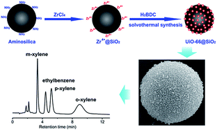
To avoid these problems, an effective strategy is to fabricate uniform spherical MOFs composites for HPLC, which combines the excellent separation ability of MOFs with the perfect packing property of spherical substrates. It is known that silica microspheres are standard packing materials for HPLC columns, thus in the previous reports MOFs were synthesized in the mesopores of silica21 or mixed with silica microspheres.29 However, the fabrication of MOFs@SiO2 shell–core microspheres is a more valuable strategy to improve chromatographic performance. Yan et al. reported the preparation of monodisperse ZIF-8@SiO2 shell–core microspheres for HPLC separation of endocrine-disruption chemicals and pesticides.23 Zhang et al. prepared HKUST-1 nanocrystals on sphere-on-sphere silica microspheres for the fast separation of toluene/ethylbenzene/styrene and toluene/o-xylene/thiophene.20
Although a variety of MOFs shell–core composites have been prepared by heterogeneous nucleation and growth of MOFs on the surface of carboxylate or hydroxylate-modified substrates, including silica,30,31 polystyrene,32 Fe3O4,33,34 and Al2O3 (ref. 35) spheres, few composites were explored as HPLC stationary phases up to now. Moreover, in most studies, the density of MOFs was controlled through altering the number of growth cycles, which would be complicated and hardly controlled.23,31–33 Herein, in this work, a facile one-pot synthesis method for the preparation of MOFs@SiO2 shell–core microspheres was developed. The loading amount of MOFs in shell–core structures could be easily regulated by adjusting the concentration of reactants, reaction temperature and time. We also made our initial efforts to assemble UiO-66 (UiO for University of Oslo) onto amino-terminated silica microspheres to prepare a novel HPLC stationary phase.
UiO-66 is a zirconium based MOF built up from hexamers of eight coordinated ZrO6(OH)2 polyhedra and terephthalate ligands.36 UiO-66 possesses a cubic rigid 3D porous structure consisting of octahedral cavities with a diameter of 1.1 nm and tetrahedral cavities with a diameter of 0.8 nm, which are connected with narrow triangle windows of a diameter of 0.5–0.7 nm. UiO-66 was used as an example of MOFs here because of its excellent stability and unique reverse shape selectivity. Except for good thermal stability, UiO-66 also exhibits a suitable mechanical stability as well as an excellent chemical resistance toward solvents such as water, benzene, dimethylformamide (DMF) and acetone.36 In addition, it is worth noting that UiO-66 is the first MOF that is observed to have reverse shape selectivity.37 Multicomponent equimolar breakthrough experiments showed that the adsorption hierarchy of structural isomers in UiO-66 is opposite to the one observed in conventional adsorbents.37 The UiO-66 shaped as powder, agglomerates and tablets also displayed an interesting o-xylene preference in the liquid phase, presenting reverse shape selectivity for the xylene isomers.38 UiO-66 particles were furthermore coated onto capillary column as the stationary phase for GC and performed reverse shape selectivity for the preferential retention of branched alkane isomers over their linear isomer.39 Recently, silica–UiO-66 composite was synthesized as HPLC stationary phase.24 However, the prepared composite was merely a mixture of silica spheres and UiO-66 nanoparticles, with few UiO-66 attached on silica surface, which may result in the problems of instability, wide particle size distribution and the leakage of UiO-66 nanoparticles through the chromatographic column filter.
In this work, the fabrication of UiO-66@SiO2 shell–core microspheres as a novel HPLC stationary phase was reported for the separation of small organic molecules including xylene isomers and ethylbenzene. The slurry-packed UiO-66@SiO2 column showed high resolution, short analysis time and good reproducibility for the separations of neutral, basic and acidic analytes, exhibiting both reverse shape selectivity and molecular sieving effect, which makes it promising for the chromatographic separation of positional isomers.
Except for varying the concentration of precursor solution, the loading amount of UiO-66 on the shell–core microspheres was also controlled by altering the reaction temperature (85 °C, 100 °C, 110 °C, 120 °C) and time (3 h, 6 h, 12 h, 24 h), under otherwise identical reaction conditions to those of UiO-66@SiO2-0.64, the detailed experimental conditions were listed in Table S1, ESI.†
UiO-66 nanocrystals were also prepared for comparison. Typically, 0.64 g of ZrCl4 in 40 mL of DMF, 0.456 g of H2BDC in 40 mL of DMF and 4.0 mL of acetic acid were mixed in a 250 mL round-bottom flask, and then the mixture was stirred at 120 °C for 24 h. After cooling down to room temperature, the white solid was collected by centrifugation and washed thoroughly with DMF. The obtained UiO-66 was then immersed in a dichloromethane solution for 3 days, dried at 60 °C under vacuum, and finally activated under vacuum at 190 °C overnight.
The surface morphologies of aminosilica and UiO-66@SiO2 shell–core microspheres prepared with different concentration of precursor solutions are shown in Fig. 2 and S1, ESI.† It can be seen that the density and particle size of UiO-66 crystals were easily controlled by adjusting the concentrations of reactants. Few UiO-66 particles were formed on the surface of aminosilica under a low precursor concentration (Fig. S1A, ESI†), and meanwhile a portion of silica microspheres were crushed. While as shown in Fig. 2C–H, the synthesized UiO-66 nanocrystals were uniformly and closely bound to the silica spheres, and the size of UiO-66 particles increased from about 60 nm to 250 nm with the precursor concentration increased. The SEM images also reveal the monodispersity and narrow particle size distribution of the prepared composites. However, with further increment of precursor concentration, an excess of individual UiO-66 nanoparticles existed in the product which were difficult to completely remove from the composites by centrifugation (Fig. S1B, ESI†). A higher precursor concentration gave rise to the formation of the irregular lamellar UiO-66, as can be observed from Fig. S1C, ESI.† The above SEM results indicate the successful fabrication of UiO-66 shell on silica core with controllable density and particle size.
![]() | ||
Fig. 2 SEM images of (A and B) NH2–SiO2; (C and D) UiO-66@SiO2-0.16; (E, F) UiO-66@SiO2-0.32; (G, H) UiO-66@SiO2-0.64. |
FTIR spectra (Fig. 3A) were further recorded to evaluate the fabrication of UiO-66@SiO2 composites. In the FTIR spectra of UiO-66@SiO2 composites, the appearance of the characteristic peaks of UiO-66 at around 1664, 1585, 1506, 1395 and 745 cm−1 confirms the successful incorporation of UiO-66 onto the aminosilica. Moreover, the intensity of these characteristic peaks increases gradually with the concentration of precursor solutions, indicating a progressively increasing loading amount of UiO-66 nanocrystals. Besides, the peaks at 1102 and 798 cm−1 are assigned as the stretching vibration of Si–O–Si and bending vibration of SiO–H, respectively. The XRD results could also proof the formation of UiO-66@SiO2 composites, as shown in Fig. 3B. Both the characteristic peaks of UiO-66 and the characteristic signal of aminosilica at 20–25° are observed on the XRD patterns of UiO-66@SiO2 composites. Additionally, the signal intensity of the characteristic peaks of UiO-66 increases with the concentration of precursor solutions, which is consistent with the FTIR results.
From Fig. 3C, the isotherm curve of UiO-66 by N2 sorption exhibits a type I plot, indicating its typical microporous structure. However, the isotherm curves of the UiO-66@SiO2 composites show a type IV plot due to the mesoporous structure of silica microspheres. The increased BET specific surface areas of the UiO-66 coated composites (276.0 m2 g−1 for UiO-66@SiO2-0.16, 308.9 m2 g−1 for UiO-66@SiO2-0.32 and 371.1 m2 g−1 for UiO-66@SiO2-0.64) as compared to the bare aminosilica (269.9 m2 g−1) also imply the effective loading of UiO-66 (930.6 m2 g−1) on the silica surface. For the three kinds of.
UiO-66@SiO2 composites, the ratio of micropore area to total surface area rises from 10.1% to 45.9% with the increment of UiO-66 loading amount. Thermogravimetric analysis results (Fig. 3D) show that the composites contain four parts in weight loss, which correspond to the surface water evaporation (<403 K), the loss of solvent molecules trapped inside the micropores (473–573 K), the decomposition of the organic linkers of UiO-66 (753–793 K) and the decomposition of amino groups on aminosilica (473–773 K). The residue was identified to be SiO2 and ZrO2. Based on the TG weigh losses, the weight percentages of UiO-66 in the composites were calculated to be 12.7% for UiO-66@SiO2-0.16, 18.6% for UiO-66@SiO2-0.32 and 26.2% for UiO-66@SiO2-0.64.
The density and particle size of UiO-66 nanocrystals could also be tuned through altering the reaction temperature and time, since they are the key factors that influence the crystal growth.
Comparing the SEM images in Fig. 4A–C and 2H as well as the FTIR spectra in Fig. 4D, it can be seen that the sample prepared at 85 °C did not exhibit obvious formation of UiO-66 particles owing to the low crystallinity of UiO-66 under this condition. However, with the increased reaction temperature, a gradually denser UiO-66 shell was observed, and the characteristic signals of the UiO-66 structure became more distinct in the FTIR spectra. This is due to the improved growth of UiO-66 crystals at higher temperature. Similarly, extending the reaction time could also lead to the increase in UiO-66 loading amount and particle diameter, as shown in Fig. 5 and 2H. The XRD patterns of the UiO-66@SiO2 composites synthesized under different reaction temperature and time are listed in Fig. S3 and S4, ESI.†
![]() | ||
Fig. 5 SEM images of UiO-66@SiO2 composites synthesized at 120 °C for (A) 3 h; (B) 6 h; (C) 12 h; (D) FTIR spectra of UiO-66@SiO2 composites synthesized at 120 °C for 3 h, 6 h, 12 h and 24 h. |
The stability of UiO-66 shell plays an important role in the application of UiO-66@SiO2 microspheres as HPLC stationary phase. Hence, to investigate their stability, the composites were treated under dramatic ultrasonic in a dichloromethane solution for 10 minutes, and then collected by centrifugation. From the SEM images exhibited in Fig. S5, ESI,† it is noticed that the UiO-66 nanocrystals were bound firmly to the silica microspheres without obvious detachment by the applied treatment, thus implying the good stability of the shell–core composites.
Fig. 6 shows the separation of four groups of analytes on UiO-66@SiO2-0.16 packed column. The relative standard deviations (RSDs) of the retention time for six replicate runs were in the range of 0.10–0.46% for xylenes and ethylbenzene, 0.06–0.24% for alkyl benzenes, 0.07–0.38% for anilines and 0.09–0.35% for substituted benzenes, respectively, showing the good reproducibility. Furthermore, the UiO-66@SiO2 packed column was retained for at least 400 runs over one month without observable change in the chromatographic performance. These results indicate the high stability and reproducibility of the prepared UiO-66@SiO2 packed column. The UiO-66@SiO2 packed column also exhibits good permeability. With the flow rate of the mobile phase (100% ACN) increases from 1.0 to 5.0 mL min−1, the column backpressure increases linearly from 13.05 to 67.12 bar (Fig. S6, ESI†). Compared with the high column backpressure caused by the direct packing of MOFs particles, the UiO-66@SiO2 packed column gives a very low backpressure, which is attractive for its application in HPLC separation. The role of the mobile phase composition in HPLC separation was also studied in Fig. S7, ESI.† Fast and high-resolution separation of analytes could be achieved on UiO-66@SiO2 packed column through controlling the composition of mobile phase.
The separation performance of C18 column was also investigated for comparison. As shown in Fig. S8, ESI,† although a much higher percentage of ACN was applied as mobile phase, longer analysis time was needed for complete separation of the three groups of analytes (alkyl benzenes, anilines and substituted benzenes) on C18 column, thus indicating the fast separation of UiO-66@SiO2 packed column. Besides, ethylbenzene and xylenes were hardly separated on C18 column because of their similar hydrophobicity.
To study the effect of UiO-66 shell on the chromatographic separation, these analytes were also separated on the aminosilica packed column with different composition of the mobile phase for comparison (Fig. 7). However, the aminosilica packed column provided a poor resolution for the tested analytes. Adjustment in the mobile phase composition brought about no obvious improvement of the separation. The abundant amino groups on the surface of silica could lead to the formation of hydrogen bond with analytes, and this is the main separating power of the aminosilica packed column. Therefore, p-phenylenediamine with two amino groups obtained the longest retention time in the separation of aniline compounds (Fig. 7C), and similarly aniline exhibited the strongest retention in the separation of substituted benzenes (Fig. 7D). The result indicates that the UiO-66 shell played a significant role in the effective separation of the four groups of analytes on UiO-66@SiO2 packed column.
![]() | ||
Fig. 7 Chromatograms of the separation of (A) xylenes and ethylbenzene, (B) alkyl benzenes, (C) anilines and (D) substituted benzenes on aminosilica packed column with different ratio of ACN/H2O as mobile phase. Other separation conditions are identical to Fig. 6. |
The loading amount of UiO-66 shell also made an obvious influence on the chromatographic performance. Three composites (UiO-66@SiO2-0.16, UiO-66@SiO2-0.32 and UiO-66@SiO2-0.64) were investigated as HPLC stationary phases. As exhibited in Fig. 8, aniline compounds (p-phenylenediamine, aniline, N,N-dimethylaniline and p-chloroaniline) were selected as an example to study the role of UiO-66 loading amount in the HPLC separation. The retention on the UiO-66@SiO2 packed columns depends on the synergic effect of the hydrogen bonding between the compounds and the amino groups on the surface of aminosilica, and the hydrophobic effect as well as π–π stacking interaction between the compounds and the organic linkers of UiO-66 shell. As the UiO-66 loading amount increased, the hydrogen bonding between anilines and amino groups decreased, whereas the hydrophobic interaction and π–π stacking interaction between anilines and UiO-66 shell increased. Hence, as can be seen from Table S2, ESI,† the retention factors of p-phenylenediamine, aniline and N,N-dimethylaniline firstly decrease as the UiO-66 load raises from 12.7% (UiO-66@SiO2-0.16) to18.6% (UiO-66@SiO2-0.32), and afterwards increase with the UiO-66 load increases to 26.2% (UiO-66@SiO2-0.64). While unlike other aniline compounds, the retention factor of p-chloroaniline increases gradually with the increment of UiO-66 coating, since the p–π conjugate effect existing between the lone pair electrons of chlorine atom and the aromatic rings of UiO-66 contributed to the strong retention of p-chloroaniline. The above results prove that the UiO-66 loading amount has an important effect on the retention and resolution of analytes.
Effective separation of neutral alkyl benzenes was also realized on the UiO-66@SiO2 packed column (Fig. 6B). The retention order of benzene < toluene < p-xylene indicates that the retention behavior corresponds to the hydrophobic interaction between the compounds and the aromatic walls of UiO-66. However, TMB, with the strongest hydrophobicity, shows the weakest retention on the UiO-66@SiO2 packed column. The bulky TMB molecules with a critical diameter of 0.86 nm, which is much larger than the pore window size (0.5–0.7 nm) and tetrahedral cavities diameter (0.8 nm) of UiO-66, were excluded from the micropores of UiO-66 and could only be adsorbed through surface interaction, thus leading to its shortest retention time. The experimental result reveals the existence of molecular sieving effect on the UiO-66@SiO2 packed column. Additionally, the retention time of polycyclic aromatic hydrocarbons (PAHs) followed an increasing order of acenaphthene < phenanthrene < naphthalene (Fig. S9, ESI†), which is not in accordance with both the hydrophobic interaction and π–π interaction between the PAHs and the UiO-66 stationary phase. The strongest retention of naphthalene is attributed to its smaller molecule size relative to acenaphthene and phenanthrene, further supporting the presence of molecular sieving effect.
Four kinds of basic aniline compounds were baseline separated on the UiO-66@SiO2 packed column with high resolution and good reproducibility in 6 minutes (Fig. 6C). The hydrophobicity strength of anilines follows the order of p-phenylenediamine < aniline < p-chloroaniline < N,N-dimethylaniline, while N,N-dimethylaniline was eluted earlier than p-chloroaniline on the UiO-66@SiO2 packed column. The longer retention time of p-chloroaniline is ascribed to the p–π conjugate effect existing between the lone pair electrons of chlorine atom and the benzene rings of organic linkers in UiO-66.
The UiO-66@SiO2 packed column also showed satisfactory separation performance for the substituted benzenes (Fig. 6D). The elution order of aniline, nitrobenzene and toluene is in accordance with the hydrophobic interaction between the solutes and the aromatic walls of UiO-66 shell. However, the p–π interaction between the chlorine atoms and the aromatic rings of UiO-66 gave rise to the longest retention time of chlorobenzene.
The HPLC columns packed with UiO-66@SiO2 shell–core composites and aminosilica microspheres were subsequently used for the separation of phenol, 2-chlorophenol and 2,4-dichlorophenol. From the chromatograms shown in Fig. S10, ESI,† it can be seen that the three acidic phenolic compounds were effectively separated on the two columns under their optimal separation conditions. However, the intense interaction between chlorine substituent groups and the UiO-66 shell results in the obvious peak broadening and tailing of 2-chlorophenol and 2,4-dichlorophenol on the UiO-66@SiO2 packed column, which is consistent with the separation performance of p-chloroaniline and chlorobenzene.
Footnote |
† Electronic supplementary information (ESI) available: Detailed synthesis conditions, additional tables, SEM images, XRD patterns and HPLC results. See DOI: 10.1039/c4ra12263a |
This journal is © The Royal Society of Chemistry 2015 |