DOI:
10.1039/C4RA12088D
(Paper)
RSC Adv., 2015,
5, 5183-5191
Charge-selective membrane protein patterning with proteoliposomes†
Received
9th October 2014
, Accepted 5th December 2014
First published on 9th December 2014
Abstract
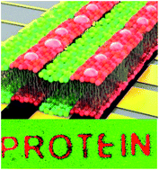
A novel method to fabricate transmembrane protein (TP) embedded lipid bilayers using microcontact printing and applying proteoliposomes to different types of substrates, has been developed. The electrostatic interaction between the negatively charged proteoliposome and the substrate, which had been positively functionalized by microcontact printing, allowed the formation of TP-embedded, patterned lipid bilayers. The positively charged amino functional group on the substrate did effectively attract the negatively charged vesicles, inducing them to be adsorbed and subsequently ruptured to form a giant mosaic lipid bilayer, resulting in an immobilized TP-embedded lipid layer precisely on the targeted patterns, which were backfilled with a zwitterionic lipid bilayer. The rapid and highly selective recognition of the charged liposomes was visualized, and the biological functions of the TPs in the lipid matrix were also observed.
Introduction
Transmembrane proteins (TPs) are a class of integral membrane proteins that regulate the transport of biological substances across cellular membranes. Depending on the driving potentials, TPs are categorized as light-driven proteins (e.g., rhodopsin, photosystem I and II, light-harvesting complexes),1 redox-driven proteins (e.g., cytochrome complexes),2 and electrochemically-driven transporters (e.g., ATPases, and ion channels).3 While permanently bound to lipid-based membranes, TPs take on a wide range of roles in interactions with diverse biological substances, such as channels for ions, receptors for biological signal molecules, and enzymes for biological essential products or waste byproducts. A variety of their biological activities have been extensively studied in vivo over the last few decades. Because of their importance in energy-harvesting and signal-transducing functions and their functioning efficiency in nature, their potential in vitro applications have drawn both scientific and technological interest. However, their structural vulnerability when they are exposed to non-native environments limits the development of any promising devices; the hydrophobic portions of purified transmembrane proteins easily denature without a cell membrane-like lipid environment.4 Hence, to maintain their three-dimensional structures and robust functions, cell membrane-mimicking matrices, such as a supported lipid bilayer (SLB) for solid substrates5 or unilamellar lipid vesicles for bulk vesicles,6 are required at the reaction fronts of working devices.
A large number of surface-confined membrane models have been developed using various lipid-bilayer formation methods to achieve suitable membrane properties, with the most popular methods being (1) a vesicle fusion technique,7 the formation of lipid bilayers through the spreading of small unilamellar vesicles (SUVs) via spontaneous adsorption on predetermined spots on a substrate, and (2) Langmuir deposition onto a substrate.8 Compared to the freely suspended lipid membranes in a vesicle, in the case of SLBs, the proximity to a rigid substrate (silicon, metal, or polymer) could in fact restrict the molecular dynamics due to the attractive interaction between the inner leaflet and the substrate. Despite this intrinsic limitation of SLBs, the various possible biotechnological applications, such as enzyme reactors, biosensors, and energy-harvesting devices, that could be used to enhance the efficiency of conventional signal-transducing devices mimicking processes observed in nature have motivated research on TP-reconstituted lipid bilayers on predetermined substrates, such as silicon oxide, metallic electrodes, and conducting oxides.9 In recent decades, a number of research groups have developed various fabrication methods with the aim of producing TPs-embedded lipid bilayers using polymer tethers,10 detergents,11 and self-inserting TPs12 on solid substrates. In particular, great efforts have been made to develop a simple, reproducible, and robust method that would allow homogeneous SLB patterns, without any additional chemistry (e.g., tethered molecular supports) to be formed on a predetermined surface. For example, the vesicle fusion method is known to provide highly homogeneous bilayers directly on preconditioned substrates.13 Researchers have stated that the goal of their novel SLB techniques is to provide a potential cell membrane-mimicking lipid platform. However, as far as we know, a successfully functioning TPs-incorporated lipid bilayer has never been reported. Kumar et al.14 reported the formation of electrochemically mediated SLBs from the rupture of anionic vesicles in the presence of Ca2+ ions on indium tin oxide (ITO)-coated surfaces, yet no TP-reconstituted bilayers were demonstrated. If anionic liposomes can selectively recognize targeted spots and rupture to form a homogeneous SLB, then this result must be tested with protein-reconstituted liposomes (proteoliposomes) instead of lipid-only vesicles to confirm whether the TPs-embedded SLBs from the proteoliposomes can be prepared on planar substrates.
In this paper, we would like to detail a novel method which provides the most effective and easiest, universal way to pattern the transmembrane proteins-incorporated lipid bilayers on various substrates via an indirect microcontact printing (μCP) method. As described earlier, our results are showing successfully that TPs-incorporated lipid bilayer can be patterned on various substrates without any special treatments such as the polymer based cushion layers or chemically tethered lipid layer. The electrostatic interaction between the negatively charged proteoliposome and the substrate, which had been positively functionalized by the μCP, allowed the formation of TP-embedded, patterned lipid bilayers. This method is resulting in an immobilized TP embedded lipid layer precisely on the targeted patterns. The rapid and highly selective recognition of the charged liposomes was visualized, and the biological functions from the TPs in the lipid matrix were also observed. These results extend our general methods to provide a bio-platform for devices using transmembrane proteins and research into the functionalities of membrane proteins in cell membrane-like environments.
Experimental
Materials and methods
Materials. 1,2-Dioleoyl-sn-glycero-3-phosphocholine (DOPC) and 1,2-dioleoyl-sn-glycero-3-phospho-L-serine (DOPS) were purchased from Avanti Polar Lipids (Alabaster, AL). Texas Red-1,2-dihexadecanoyl-sn-glycero-3-phosphoethanolamine (Texas Red-PE) and N-(7-nitrobenz-2-oxa-1,3-diazol-4-yl)-1,2-dihexadecanoyl-sn-glycero-3-phosphoethanolamin (NBD-PE) were purchased from Invitrogen (Eugene, OR). APTES, cysteamine (≥98.0%), 4-(2-hydroxyethyl)piperazine-1-ethanesulfonic acid (HEPES), n-dodecyl β-D-maltoside (DM), and phenylmethanesulfonyl fluoride (PMSF) were purchased from Sigma Aldrich (St Louis, MO). Bio-Beads SM-2 adsorbent was purchased from Bio-Rad (Hercules, CA). LHC II proteins were provided by Prof. Tae Kyu Ahn's lab, Dept. of Energy Science, Sungkyunkwan University, and Proteorhodopsin (PR) proteins were provided by Prof. Kwang-Hwan Jung's lab, Dept. of Life Science, Sogang University. Detailed purification processes are described below. Ethanol, sulfuric acid, and hydrogen peroxide were purchased from Jin Chemical Co., Ltd. (Siheung, South Korea). All chemical reagents and solvents were used without further purification. Deionized water (∼18.2 mΩ cm) was obtained using an ultrafiltration system (PURELAB Classic, ELGA LabWater). Four types of substrates (silicon- and gold-coated wafers, glass coverslip, and ITO-coated slide glass) were used for bilayer formation. Single side polished silicon wafer (p-type [100]) was purchased from LG Siltron. Gold-coated silicon wafer was purchased from Sigma Aldrich (St Louis, MO). Glass coverslips were purchased from Paul Marienfeld GmbH & Co. KG (Lauda-Königshofen, Germany). Poly(dimethylsiloxnane) (PDMS) stamps for μCP were prepared using a set of Sylgard 184 A and B from Sewang Hitech (Gimpo, South Korea).
Substrate cleaning. Silicon wafers, gold-coated silicon wafers, glass coverslips, and ITO-coated slide glasses were sonicated in 70% ethanol for 50 min and washed with deionzed (DI) water. They were cleaned in a piranha solution (mixture of H2SO4 and 30% H2O2, volume ratio = 7
:
3) for 1 h at 80 °C. They were washed with deionized water and dried with nitrogen gas flow.
Preparation of PDMS stamps and patterned substrate. PDMS stamps were fabricated with sylgard 184 A and B. The sylgard A and B were vigorously mixed at the weight ratio of 10
:
1 A
:
B for 5 min. The entire mixture was filled with bubbles, gently poured over the designed master, and degassed for 1 h. After degassing, it was incubated in a 70 °C oven for over 6 h. All substrates (silicon wafers, gold-coated silicon wafers, glass coverslips, and ITO-coated slide glass) were treated by UVO cleaner (AH-1700, Ahtech LTS, Anyang-si, Korea) for 20 min. Aqueous solutions of 1% APTES (v/v) and 0.3% (w/v) cysteamine were respectively dropped on patterned PDMS stamps. The PDMS stamps were incubated for 40 min at room temperature and dried with nitrogen gas flow. The APTES-coated PDMS stamps were put in contact with the silicon wafer, glass coverslip, and ITO-coated slide glass for 1 min. The cysteamine-coated PDMS stamp was put in contact with the gold coated silicon wafer for 2 min.
Expression and purification of PR. PR was expressed under the lacUV5 in E. coli (strain UT5600) cells. The UT5600 cells, transformed with pKA001 and including PR, were grown in LB broth supplemented with 50 μg mL−1 ampicillin until the optical density of the cells at 600 nm reached 0.4 OD. They were then induced with 1 mM IPTG (Applichem) and ∼5–10 μM all-trans retinal (Sigma-Aldrich Co.) and grown for 6 h at 35 °C. The induced cells were centrifuged at a low speed (4000 rpm) and washed again. After breaking cells by sonication (Branson Sonifier 250), membrane pellets were precipitated by ultracentrifugation (Ti70 rotor, Beckman XL-90). The membranes were solubilized with 1% DM, and the proteins were purified with Ni2+-NTA agarose (Qiagen). The purified samples contained 0.02% DM.
Purification of light-harvesting complex (LHC) II. LHC II was purified from spinach. Spinach leaves were briefly ground in 20 mM tricine–KOH (pH 7.8), 0.2 M NaCl, 0.2 M sorbitol, 2 mM MgCl2, and the protease inhibitors 0.2 mM benzamidine, 1 mM h-aminocaproic acid, and 0.2 mM PMSF. The solution was centrifuged for 10 min at 1000g. The pellet was washed once by centrifugation in the same buffer and then pellet was resuspended in buffer solution containing 20 mM tricine–KOH (pH 7.8), 0.15 M NaCl, 5 mM MgCl2, and the protease inhibitors 0.2 mM benzamidine, 1 mM h-aminocaproic acid, and 0.2 mM PMSF. This solution was centrifuged for 10 min at 4000g, and the pellet was resuspended in 20 mM HEPES (pH 7.5), 15 mM NaCl, and 5 mM MgCl2 and centrifuged again for 10 min at 6000g. To solubilize stacked thylakoids, the solution was incubated in 3% DM (w/v), 15 mM NaCl, and 5 mM MgCl2 for 20 min on ice and with soft agitation. To remove non-solubilized material, a 5 min centrifugation at 2000g was done. Membranes were resuspended in a small volume of 20 mM HEPES (pH 7.5), 0.4 M sorbitol, 15 mM NaCl, and 5 mM MgCl2. For the LHC II preparations, the solubilized samples were centrifuged on a sucrose gradient in a SW28 rotor for 36 h at 4 °C and 80
000g. Gradients were formed directly in the tube by freezing at −80 °C and thawing at 4 °C with 0.65 M sucrose sugar solution containing 0.03% DM and 10 mM HEPES (pH 7.5). All experiments were conducted at 4 °C.
Preparation of SUVs. SUVs were prepared by extrusion. DOPC/DOPS/Texas Red-PE in a molar ratio of 80
:
20
:
0.5 and DOPC/NBD-PE in a molar ratio of 100
:
3 were respectively mixed in chloroform with mixing maintained for 15 min. They were dried on the bottom of the vial by nitrogen gas flow, and secondary drying was conducted in a vacuum desiccator for 3 h. After vacuum drying, the DOPC/DOPS/Texas Red-PE lipid films were resuspended in 10 mM HEPES buffer (pH 7.4) or 20 mM Tris buffer (pH 7.01, 150 mM NaCl) for 30 min, and the concentration of the total lipid was 5 mg mL−1. For DOPC/NBD-PE lipid film, 1× PBS buffer (pH 7.4, 3 mM Na2HPO4, 150 mM NaCl) was used. The hydrated lipids (multilamellar vesicles, MLVs) were kept above the phase transition temperature of the lipid before extrusion. The MLVs were mainly changed into large unilamellar vesicles (LUVs) by freezing and thawing. The LUVs in micro test tubes were dipped into liquid nitrogen for 2 min, and the tube was transferred to a water bath (50 °C) for 3 min. This cycle was repeated 15 times. The extrusion was performed by a mini-extruder (Avanti Polar Lipids, Alabaster, AL). The lipid solution was extruded with 0.1 μm polycarbonate membrane filters (Whatman, Inc., Newton, MA) at room temperature. The vesicles were passed through the membrane filter a minimum of 21 times. The SUVs were stored at 4 °C.
Reconstitution of TPs into SUVs. Purified LHC II proteins in 0.06% DM were mixed with preformed SUVs (DOPC/DOPS/Texas Red-PE) containing 3% DM at protein/lipid molar ratio of 1
:
500 in a HEPES buffer (10 mM, pH 7.4). The mixture was incubated for 30 min at 4 °C. To remove the detergent, the mixture was dialyzed with a HEPES buffer (10 mM, pH 7.4, 0.2 mM PMSF, 2 L) for 4 days at 4 °C in the dark. The buffer was exchanged with new buffer twice per day. The method for the reconstitution of PR proteins was very similar to the case of LHC II proteins. The PRs were stabilized in 20 mM Tris buffer containing 0.02% DM (pH 7.01, 150 mM NaCl). We used a P/L ratio of 1
:
500 to reconstitute PRs into SUVs and a 20 mM Tris buffer (pH 7.01, 150 mM NaCl, 2 L) as the dialysis buffer. After dialysis, the proteoliposomes were stored at 4 °C and used within one week.
Formation of TPs-patterned SLBs on solid support. Negatively charged proteoliposomes (DOPC/DOPS/Texas Red-PE/LHC II or PR) were diluted with a HEPES buffer (pH 7.4, 10 mM) or a Tris buffer (20 mM, pH 7.01, 150 mM NaCl) to a final concentration of 50 μg mL−1. The neutrally charged vesicles (DOPC/NBD-PE) for backfilling were diluted with a 1× PBS buffer to a final concentration of 100 μg mL−1. The surfaces of APTES-patterned silicon wafers, glass coverslips, and ITO-coated slide glass were entirely covered with a solution of negatively charged proteoliposomes for 10 min. The surfaces were rinsed with deionized water several times, and the TPs-patterned lipid bilayers formed on the substrates. Subsequently, the substrates were incubated with zwitterionic SUVs (DOPC/NBD-PE) at room temperature for 20 min and rinsed with deionized water. The TPs-patterned SLBs were backfilled with zwitterionic lipid bilayer using DOPC/NBD-PE SUVs. To form the TPs-patterned lipid bilayer on the cysteamine-coated gold wafer, the above procedures were used without backfilling. All experiments were carried out in the dark, and the bilayer was not exposed to the air.
Fluorescent microscopy. Fluorescent microscopy was performed on a Nikon ECLIPSE TE2000-U (mercury lamp, 100 W) with two fluorescence filters: excitation BP400-490 nm, emission LP520 nm (B-2A for NBD-PE); excitation BP540-580 nm, emission BP600-660 nm (Y-2E/C for Texas Red). Fluorescent images were obtained using Plan Fluor 10×/0.30 or Plan Fluor ELWD 20×/0.45 objectives.
Confocal microscopy. The morphology of TPs-patterned lipid bilayers, which were prepared on glass coverslips with various sized and shaped patterns, was obtained with confocal microscopy at 488/543 nm excitation and 505–533/560 LP emission (Zeiss LSM 5 Exciter, Carl Zeiss and Leica TCS SPE, Leica Microsystems). The glass coverslip was assembled with a Chamlide magnetic chamber (CM-B25-1PB, Live Cell Instrument, South Korea).
Fourier-transform infrared (FT-IR) imaging. FT-IR analysis was performed with a Cary 660 spectrometer and Cary 620 microscopes using a 16 × 16 focal plane array detector (Agilent, Santa Clara, CA). The samples for FTIR measurements were prepared with silicon wafers. TPs-patterned lipid bilayers on the silicon substrate were carefully removed from the water system and dried overnight in a vacuum chamber. FT-IR images and spectra were obtained at 1654 and 2923 cm−1 by transmission mode. Measurement conditions of 32 scans and 4 cm−1 were used.
Time-of-Flight Secondary Ion Mass Spectrometry (ToF-SIMS). Negative ion TOF-SIMS analyses were carried out using a ToF-SIMS 5 reflectron-type time-of-flight mass spectrometer (ION-TOF GmbH, Műnster), with a bismuth liquid metal ion gun as the primary ion source. A 25 keV Bi+ liquid metal ion source was employed for mass spectra and ion image acquisition. A low-energy electron flood gun was used for charge compensation of the SLB samples. Ion images were collected for the selected set of ion masses from an area of 300 × 300 μm. The mass spectra for SLBs were collected from an area of 100 × 100 μm2. The detected intensity of each peak was normalized to a correction factor using the total intensity over the analyzed area.
X-ray reflectivity. To analyze the vertical structure of SLBs containing proteins the X-ray reflectivity was measured by diffractometry (Bruker D-8), and the results are presented in Fig. S4.† The reflectivity of APTES (black triangle) that looks like Fresnel reflection seems not to have interference fringe, implying that it is either a thick or thin film. On the reflectivity data for two SLB samples with (white circle) and without (black circle) PRs, the interference fringes show apparent corresponding thicknesses of ∼5 nm for both, which clearly represent the bilayer structure of a typical phospholipid. Any noticeable difference between the two different SLBs (with and without PRs). Based on the fact that the electron density of the amino end group of the embedded proteins does not significantly contribute to the reflectivity, we assume that the distribution and height of embedded proteins on SLBs are homogenous.
Patch-clamp experiment: TP activities. Patch-clamp experiments were performed with a planar patch clamp system (Port-a-Patch, Nanion Technologies GmbH, Munich, Germany) and an EPC-10 patch clamp amplifier (HEKA, Lambrecht, Germany), using borosilicate glass chips with an aperture diameter of approximately 2 μm. Extracellular buffer solution (140NaCl, 4KCl, 1MgCl2, 2CaCl2, 5D-glucose monohydrate, 10HEPES [mM], pH 7.4) and intracellular buffer solution (50KCl, 10NaCl, 60KF, 20EGTA, 10HEPES [mM], pH 7.2) was introduced into the chip prior to flowing lipid solution into the chamber. For the formation of a planar lipid bilayer containing PRs, 5 μL of the proteoliposome solution was pipetted onto the patch clamp chip. The GUVs were positioned onto the aperture in the chip by the application of a negative pressure. Generally, (−)5 to (−)30 mbar was sufficient for reliable positioning within a few seconds after GUV addition. When the GUVs touched the glass surface of the chip, they burst and formed planar bilayers15 with a seal resistance of at least 1 GΩ. The membrane capacitance was estimated to be on the order of a few fF. Photocurrents were induced by illumination with light from a SPECTRA light engine (Lumencor, OR), which was filtered by a band pass filter (540 ± 27 nm, FF01-542/27, Semrock, NY) to yield green light (42.3 mW cm−2). Light was directed on the lipid bilayer via an optical fiber. All experiments were carried out at a temperature of 20 °C–22 °C and the membrane potential was held at −20 mV.
Results and discussion
In this article, we describe a novel method to fabricate the TP-embedded phospholipid bilayers via an indirect microcontact printing (μCP) method. Due to the inherent structure of the zwitterion and strong silanization properties of (3-aminopropyl) triethoxysilane (APTES) in water, μCP of APTES readily provides silanol bonds on the oxide surface and provides positively charged amine layer at the other end of APTES, electrostatically attracting the negatively charged proteoliposomes. The strategy and the process of this method are schematically illustrated in Scheme 1 and described as four main steps: (i) APTES monolayers are patterned on oxidized substrates by μCP. (ii) Membrane proteins are reconstituted into negatively charged lipid vesicles, followed by dialysis to remove the detergent. (iii) The proteoliposome solution is dropped, and it selectively ruptures on the APTES-patterned surface. (iv) The patterned TP embedded lipid bilayers are backfilled with a zwitterionic lipid bilayer. In detail, 1% APTES in deionized water was used to cover variously patterned PDMS stamps. The stamps were then put in contact with an oxidized cover glass, a silicon wafer or an ITO coated slide glass. The net negatively charged proteoliposome solution by the mixture of 20% of 1,2-dioleoyl-sn-glycero-3-phospho-L-serine (DOPS, z = −1) into 1,2-dioleoyl-sn-glycero-3-phosphocholine (DOPC, z = 0), which was prepared using a reconstitution of two integral membrane proteins, LHC II, or PR, was dropped onto the APTES-patterned surface and incubated for 10 min. The proteoliposomes were selectively ruptured and spread on the patterned APTES surface, primarily due to their strong electrostatic attraction to the positively charged amino groups of APTES. In this process, the SUVs appeared to rupture into an infinite number of tiny mosaic bilayer patches, thus forming a lipid bilayer that spreads to cover the entire area of the APTES. After the targeted protein-incorporated lipid bilayers had been formed, the whole system was gently washed with an appropriate buffer to remove the residual lipid vesicles. As a final step, the substrate was dipped into a solution of pure DOPC vesicles to backfill the uncovered region of the APTES area in a way similar to that used for the charged proteoliposomes. The cations (e.g. Na+) in the buffer solution link to pin down the zwitterionic lipid vesicles to the uncovered, –OH surface, and they form the TP-free lipid bilayers.16
 |
| Scheme 1 Schematic representation of the fabrication of TP embedded SLB on a substrate by indirect μCP of APTES patterns. | |
To identify whether the TP-embedded lipid bilayers are formed along the pre-existing APTES patterns, we used confocal fluorescence microscopy, enabling the two-dimensional morphologies to be monitored using the contrast between fluorescent patterns stained with two distinct markers: red-colored Texas Red-1,2-dihexadecanoyl-sn-glycero-3-phosphoethanolamine (Texas Red-DHPE) for the protein-incorporated liposomes and green-colored N-(7-nitrobenz-2-oxa-1,3-diazol-4-yl)-1,2-dihexadecanoyl-sn-glycero-3-phosphoethanolamin (NBD-PE) for the pure lipid liposomes. In Fig. 1, the incorporation of two different TPs, LHC-II (Fig. 1a–d) and PR (Fig. 1e and f), extracted from spinach and E. coli, respectively, was demonstrated in order to present the universality of this method. To sustain the boundary of the TP-embedded patch pattern, we further backfilled the empty areas with pure phospholipids by adding a solution of pure DOPC vesicles (dyed with NBD-PE) into the solution containing the TP-patterned substrate. The small ruptured patches from the SUVs spread and filled in the gaps of the TP-embedded patterns. The images in Fig. 1 suggest that circular, narrow-striped, and wide-striped patterns were formed on the micro-patterned APTES, regardless of which TPs were incorporated. Although this backfilled SLB is in a floating state, unlike the tightly bound state of printed SLBs, the backfilled SLB molecules may physically enclose the TP-incorporated patterns and maintain the incorporation of TPs in the lipid matrix on the substrates. As shown in Fig. 1a–d, the LHC II-embedded lipid patches, marked in red, can be distinguished from the backfilled SLB, marked in green; the boundaries of the patterned SLBs, the shapes with circular curvatures, and the straight lines are all highly contrasted. The observed impurity islands of red spots in the green area of the SLB can be attributed to residues from proteoliposomes that were randomly attached during the liposome rupture process. The quantitative intensity of the confocal microscope image supports the degree of sharpness of this contrast, as shown in the bottom inset. When we compared these measured geometric values to those of the original PDMS stamp mask, the resolution of the indirectly-deposited SLBs were well preserved, which indicates implicitly that the patterns with the directly printed APTES linker were uniformly bound on the substrate and, consequently, selectively retained the negatively charged TP-embedded lipid patches.
 |
| Fig. 1 Confocal microscope images of TP embedded SLB patterns, fabricated by indirect μCP on a glass substrate with different TPs. Red colors correspond to SLBs (DOPC : DOPS : Texas Red-PE = 80 : 20 : 0.5) including TPs: (a–d) LHCII and (e and f) PR. Green colors are TPs-free SLBs (3% of NBD-PE in DOPC). (f) In situ observation of the process of SLB formation. Scale bars: 50 μm. Bottom inset in (a): the fluorescent intensity of red patterns. The dimensions of PDMS stamps' micropatterns used in the figures are (a) diameter (d) = 50 μm and gap (g) = 25 μm; (c) d = 40 μm and g = 30 μm; (d) line width (w) = 15 μm and g = 15 μm; (e) w = 65 μm and g = 85; (f) 200 μm × 40 μm. | |
As previously reported, SUVs are geometrically unstable, readily rupturing when they come into contact with the silicon oxide surface.17 To determine how rapidly and precisely the charged SUVs can recognize the counter-ionic charged patterns and form from proteoliposome, we used in situ confocal imaging (Fig. 1f and Movie 1†), enabling real-time monitoring of the SLB formation. We purposely formed a partial pattern to fix the focal position for microscopy in a buffered solution and injected the proteoliposome solution into the buffered solution. As shown in Fig. 1f and Movie 1,† the SLB patterns were completed in less than a second after the injection had been made, which is indicative of rapid and exclusive recognition of the proteoliposome by the counter-charged APTES surface. Note that the fluorescence intensity was stronger as a function of time, indicating that the continuous SUV fusion on the targeted areas increased the lipid molecular density on the pattern. Proteoliposome SLB molecules sometimes overflowed from the APTES patterns when we left the specimen for a long time (arrows in Fig. 1f, bottom-left), but the proteoliposome SLB formed exclusively at the most APTES-functionalized areas. The selectivity of the formation of the SLBs on the top end of the APTES linker was further confirmed by observing the adsorption of vesicles on the glass substrates coated with the APTES linker for two solutions, negatively charged SLBs (80 mol% DOPC and 20 mol% DOPS, Fig. S1a†) and zwitterionic SLBs (100 mol% DOPC, Fig. S1b†). From these images, the adsorptive power of the charged liposomes on the APTES surface is clearly visible, indicating that a strong electrostatic affinity may lead the proteoliposomes containing negatively charged DOPS lipids to selective adsorption and layer-formation on the positively charged APTES patterns, regardless of the buffers (e.g. PBS, HEPES, or Tris). In contrast, the zwitterionic liposomes are fused on the whole surface only under the presence of PBS buffer (Fig. S1b†) indicating only selective positive ions in the buffers can effectively screen the negative charge in the vesicle surface, activating the counter-charge attraction to the negative-charge containing backfilling space. These results clearly indicate that this method is a simple and fast route to localize TP-embedded lipid bilayers in the predetermined shape and location on that substrate. In contrast to Fig. 1a and c shows that conversion of TP-embedded and backfilled areas is easy and various example patterns are shown in ESI Fig. S2.† One might ask whether there is any way to reduce the background signal, which comes from the unwanted contact of the proteoliposomes to bare oxide surface. The rupturing time to APTES surface, however, is extremely fast (in an order of millisecond) as you can see in the Movie 1,† while as the backfilling process time is much slower (up to minutes). Therefore, when we minimized the processing time for the proteoliposome to APTES and immediately washed off the remaining solution, we could reduce the unwanted contacts and ruptures of the proteoliposomes to bare oxide surface significantly.
One question, as to whether the SLB patterns formed from the proteoliposomes retain the TPs and their functions, has not yet been answered. To confirm the presence of TPs in the SLB, we performed spectroscopic imaging measurements on the patterned specimen. FT-IR imaging and ToF-SIMS were used to look for evidence of the LHC II embedded into the fused lipid matrix by detecting absorption peaks from amide bonds and nitrogen atomic distribution, respectively. Fig. 2a shows contrasting spectra from two different positions for the LHC II-embedded SLB (dash-dot) and the lipid-only SLB (line). A distinct peak at ∼2923 cm−1, representing the alkyl stretch from the lipid molecules, was present for both layers, while the peak at ∼1654 cm−1, representing the amide I bands from the TPs, is only visible in the dash–dot curve, indicating the presence of proteins. Fig. 2b shows two-dimensional IR maps at 2923 cm−1 and 1654 cm−1 from the lipid-only (upper images) and the TP-embedded lipid (bottom images) patterns. The index bars to each figure are showing the colored intensities from blue to red, which are indicating the intensities from the background to the highest peak intensity, respectively. For the TP-embedded layers, the amide I distribution (bottom left) overlaps the phosphorus distribution (bottom right), indicating that the incorporated LHC II proteins are dispersed into the matrix of the phospholipid membranes and are successfully transferred to the targeted substrate in the form of a lipid bilayer supported by TP incorporation. In contrast, for the lipid-only SLB, no meaningful intensity (mainly blue) was observed at 1654 cm−1. These results are in agreement with Fig. 2a.
 |
| Fig. 2 Characterizations of LHC II and PR embedded into DOPC/DOPS SLBs vs. DOPC only SLBs, using (a, b) imaging FT-IR, (c, d) TOF-SIMS and (e, f) confocal microscopy. (a) IR spectra of SLBs without (solid line) and with (dash-dot) LHC II on silicon wafer. (b) 2-Dimensional IR maps at 1654 cm−1 (left) and 2923 cm−1 (right) from without (upper) and with (bottom) LHC II. (c) TOF-SIMS images (300 × 300 μm) of CN− (left) and CNO− (right) ions from SLBs without (upper) and with (bottom) LHC II on APTES patterned silicon wafer. (d) Measured ion intensities of CN− and CNO− from (c): without (black) and with (grey) LHC II in the SLBs. (e) Confocal microscope image of FITC conjugated-PR embedded SLBs on APTES patterned glass coverslips. (f) Fluorescent intensity of FITC conjugated-PR (white-dash line) in (e). Patterned line widths: (c) 70 μm and (e) 35 μm. Scale bars: (b) 11 μm; (c) and (e) 50 μm. | |
For further characterization of the membrane proteins in the SLBs, ToF-SIMS images obtained from two different surfaces of the patterned samples (SLBs with and without LHC II proteins incorporated) after they had been transferred from an aqueous system to a silicon wafer and dried overnight, are shown in Fig. 2c. To compare the ion distribution of the surfaces covered with molecules for each pattern, we plot two nitrogen-containing fragment ions at specific masses of m/z = 26.0033 (CN−) and 41.9985 (CNO−). Note that the APTES and DOPC molecules are containing CN−, so CN− peaks are localized in the SLB patterns on APTES regions (upper figures in Fig. 2c). After the TP-embedded bilayer formed on the underlying APTES pattern, the peak intensity increased more than two fold. CNO− ions, however, only exist in the sequences from the proteins. Note that the phospholipids (DOPC and DOPS) used in this experiments, are containing “CN−” components only. While as negligible intensity was observed from the APTES-patterned surface, an increase in intensity of approximately five fold was observed for the TP-embedded bilayers, confirming the presence of TPs in the SLB prepared from proteoliposomes (Fig. 2d).
Instead of florescence-tagged to lipid molecules, fluorescein isothiocyanate (FITC)-conjugated PRs have been used for the proteoliposome in Fig. 2e. As seen in the figure, the protein distributions were matched to the APTES patterns, confirming the selective and robust formation of the TP embedded SLBs. Fig. 2f is the cross-section of fluorescent intensity obtained from Fig. 2e, indicating that the PRs are successfully embedded into the matrix of lipid patterns. To determine the homogeneity of the bi-layered-membranes (not tri- or multi-layered), we performed in situ X-ray reflectivity (XR) measurements through the buffer-containing liquid cell. Fig. S3a† shows the XR curves measured for the APTES monolayer, the supported lipid bilayer without TP, and the TP-embedded supported lipid bilayer. Essentially, the total thickness of the lipid bilayers was 4.5 nm, confirming the formation of a uniform bilayer from proteoliposomes, as shown in the previous reports performed with pure lipids18 and in situ atomic force microscopy images (Fig. S3b and c†).
The critical remaining question is whether those embedded TPs prepared by our method are functioning biologically. As an example of functioning TPs, proteorhodopsin which is known to be a light-driven proton pump, was reconstituted into liposomes. If the embedded PRs function robustly, they must deliver H+ across the membrane upon activation by the absorption of green light. The PR-embedded SUVs were spread on a planar patch-clamp setup, then the photocurrents from the SLB containing PRs were measured. At pH 8.0, the photocurrent signals were detected upon illumination with 540 nm green light. As shown in Fig. 3, a 1 s exposure to green light evoked a negative photocurrent at a lipid–protein ratio of 250
:
1 (n/n), as calculated on the basis of the absorption spectrum. These repeatedly responding photocurrent signals clearly indicate that the embedded PRs function normally after having been spread on a planar substrate. By this method, we could conclude that the functional SLBs with the protein incorporated proteoliposomes can be achieved.
 |
| Fig. 3 The proton pumping activity of the reconstituted PRs was investigated by using a planar patch-clamp technique. Photocurrents in response to illumination with 540 nm green light. recorded from PR embedded lipid bilayers at pH = 8.0. Gray bars indicate the period of illumination. The power of a light-emitting diode was 42.3 mW cm−2. | |
Indirect μCP based on the silanization of APTES or the thiolation of cysteamine provides a wide choice of oxidized substrates (e.g., glasses, silicon, and indium tin oxide) and metallic surfaces (e.g., gold and silver), while the direct adsorption of liposomes may limit the selection of the substrate. To identify the substrate dependency, we further tested the TP-embedded bilayer on four different substrates: plain glass, a silicon wafer, an ITO-coated surface and a gold-covered surface. After μCP had been performed with an APTES solution (cysteamine solution substituted for Au substrate), Texas Red-PE containing proteoliposomes with LHC II were deposited. Fluorescent microscopic images of the four substrates were thus obtained and are shown in Fig. 4a–d. If the two uncoated oxidized substrates, glass and silicon, are compared superficially, both samples show similar homogeneities and micro-resolutions, as shown in Fig. 1a and b. The two conductive surfaces, which were separately coated by sputtering metal nanoparticles of ITO and gold, also show no significant loss in resolution in comparison to their corresponding uncoated dielectric surfaces, although the wafer coated with gold nanoparticles seems to have a relatively low printing quality due to the general quenching of the fluorescent intensity by the gold substrate.19
 |
| Fig. 4 Fluorescence microscope images of TP embedded SLBs on various substrates. Negatively charged liposomes (DOPC/DOPS/Texas Red-PE) were embedded with LHCII (a, b and d) and PR (c): APTES patterned glass coverslip (a), silicon wafer (b) and ITO coated slide glass (c); cysteamine patterned-gold wafer (d). Patterned line widths and gaps: (a) 15 μm and 75 μm; (b) 55 μm and 75 μm; (c) 65 μm and 12 μm, 33 μm and 15 μm; (d) 40 μm and 80 μm. Scale bar: 40 μm. | |
Conclusions
In summary, we have developed a novel method for the fabrication of membrane-protein patterned lipid bilayers using microcontact printing of functionalization reagents and simple injection of proteoliposomes on various substrates. The negatively-charged proteoliposomes, which included 20 mol% DOPS, selectively interacted with the charged patterns of substrates and were transformed into a supported lipid bilayer by virtue of the vesicle rupture process on the patterns. The empty areas of the substrate were backfilled with a neutral lipid bilayer (100 mol% DOPC). As a result, continuous lipid bilayers with membrane-protein patterns were successfully formed on substrates. The photocurrent of the light-sensitive proteins embedded in the lipid bilayers was successfully measured. We believe that this method will provide a bio-platform for devices using transmembrane proteins and research into the functionalities of membrane proteins in cell membrane-like environments.
Acknowledgements
This work was supported by the Nuclear Research R&D Program, the Mid-career Researcher Program (2011-0017539), the Advanced Research Center for Nuclear Excellence and Basic Science Research Program (2013R1A1A2010265) through the National Research Foundation of Korea funded by the Ministry of Education, Science and Technology, Korea.
Notes and references
- M. F. Hohmann-Marriott and R. E. Blankenship, Annu. Rev. Plant Biol., 2011, 62, 515–548 CrossRef CAS PubMed.
- C. J. Reedy and B. R. Gibney, Chem. Rev., 2004, 104, 617–650 CrossRef CAS PubMed.
- F. M. Ashcroft, Nature, 2006, 440, 440–447 CrossRef CAS PubMed.
- A. M. Seddon, P. Curnow and P. J. Booth, Biochim. Biophys. Acta, 2004, 1666, 105–117 CrossRef CAS PubMed.
- J. Y. Wong, J. Majewski, M. Seitz, C. K. Park, J. N. Israelachvili and G. S. Smith, Biophys. J., 1999, 77, 1445–1457 CrossRef CAS; J. Y. Wong, C. K. Park, M. Seitz and J. Israelachvili, Biophys. J., 1999, 77, 1458–1468 CrossRef; M. A. Deverall, E. Gindl, E.-K. Sinner, H. Besir, J. Ruehe, M. J. Saxton and C. A. Naumann, Biophys. J., 2005, 88, 1875–1886 CrossRef PubMed; L. Renner, T. Pompe, R. Lemaitre, D. Drechsel and C. Werner, Soft Matter, 2010, 6, 5382–5389 RSC.
- M.-T. Paternostre, M. Roux and J.-L. Rigaud, Biochemistry, 1988, 27, 2668–2677 CrossRef CAS; J.-L. Rigaud, M.-T. Paternostre and A. Bluzat, Biochemistry, 1988, 27, 2677–2688 CrossRef; P. Girard, J. Pécréaux, G. Lenoir, P. Falson, J.-L. Rigaud and P. Bassereau, Biophys. J., 2004, 87, 419–429 CrossRef PubMed; H.-H. Shen, T. Lithgow and L. L. Martin, Int. J. Mol. Sci., 2013, 14, 1589–1607 CrossRef PubMed; M. Dezi, A. D. Cicco, P. Bassereau and D. Lévy, Proc. Natl. Acad. Sci. U. S. A., 2013, 110, 7276–7281 CrossRef PubMed.
- R. G. Horn, Biochim. Biophys. Acta, 1984, 778, 224–228 CrossRef CAS; E. Kalb, S. Frey and L. K. Tamm, Biochim. Biophys. Acta, 1992, 1103, 307–316 CrossRef; R. P. Richter and A. R. Brisson, Biophys. J., 2005, 88, 3422–3433 CrossRef PubMed.
- L. K. Tamm and H. M. McConnell, Biophys. J., 1985, 47, 105–113 CrossRef CAS; J. Liu and J. C. Conboy, Langmuir, 2005, 21, 9091–9097 CrossRef PubMed.
- Y. Jing, H. Trefna, M. Persson, B. Kasemo and S. Svedhem, Soft Matter, 2014, 10, 187–195 RSC; J. Lahiri, P. Kalal, A. G. Frutos, S. J. Jonas and R. Schaeffler, Langmuir, 2000, 16, 7805–7810 CrossRef CAS; S. Gritsch, P. Nollert, F. Jähnig and E. Sackmann, Langmuir, 1998, 14, 3118–3125 CrossRef.
- T. Stora, J. H. Lakey and H. Vogel, Angew. Chem., Int. Ed., 1999, 38, 389–392 CrossRef CAS; M. L. Wagner and L. K. Tamm, Biophys. J., 2000, 79, 1400–1414 CrossRef; E. Sackmann and M. Tanaka, Trends Biotechnol., 2000, 18, 58–64 CrossRef; M. Tanaka and E. Sackmann, Nature, 2005, 437, 656–663 CrossRef PubMed.
- P.-E. Milhiet, F. Gubellini, A. Berquand, P. Dosset, J.-L. Rigaud, C. L. Grimellec and D. Lévy, Biophys. J., 2006, 91, 3268–3275 CrossRef CAS PubMed.
- M. K. Strulson and J. A. Maurer, Langmuir, 2011, 27, 12052–12057 CrossRef CAS PubMed.
- R. P. Richter, R. Bérat and A. R. Brisson, Langmuir, 2006, 22, 3497–3505 CrossRef CAS PubMed; M. R. Cheetham, J. P. Bramble, D. G. G. McMillan, R. J. Bushby, P. D. Olmsted, L. J. C. Jeuken and S. D. Evans, Soft Matter, 2012, 8, 5459–5465 RSC.
- K. Kumar, C. S. Tang, F. F. Rossetti, M. Textor, B. Keller, J. Vörös and E. Reimhult, Lab Chip, 2009, 9, 718–725 RSC.
- A. Brüggemann, C. Farre, C. Haarmann, A. Haythornthwaite, M. Kreir, S. Stoelzle, M. George and N. Fertig, Methods Mol. Biol., 2008, 491, 165–176 Search PubMed.
- T. Cha, A. Guo and X.-Y. Zhu, Biophys. J., 2006, 90, 1270–1274 CrossRef CAS PubMed.
- C. A. Keller and B. Kasemo, Biophys. J., 1998, 75, 1397–1402 CrossRef CAS; I. Reviakine and A. Brisson, Langmuir, 2000, 16, 1806–1815 CrossRef.
- E. Nováková, K. Giewekemeyer and T. Salditt, Phys. Rev. E: Stat., Nonlinear, Soft Matter Phys., 2006, 74, 051911 CrossRef.
- E. Castanié, M. Boffety and R. Carminati, Opt. Lett., 2010, 35, 291–293 CrossRef CAS PubMed; Y. Tu, P. Wu, H. Zhang and C. Cai, Chem. Commun., 2012, 48, 10718–10720 RSC.
Footnote |
† Electronic supplementary information (ESI) available. See DOI: 10.1039/c4ra12088d |
|
This journal is © The Royal Society of Chemistry 2015 |
Click here to see how this site uses Cookies. View our privacy policy here.