Synthesis of a yolk/shell Fe3O4@poly(ionic liquid)s-derived nitrogen doped graphitic porous carbon materials and its application as support for nickel catalysts†
Mohammad Reza Nabid*,
Yasamin Bide and
Zahra Habibi
Faculty of Chemistry, Department of Polymer, Shahid Beheshti University, G.C., P.O. Box 1983969411, Tehran, Iran. E-mail: m-nabid@sbu.ac.ir
First published on 18th November 2014
Abstract
The synthesis of yolk/shell spheres including a movable magnetic core, a poly(ionic liquid)s-derived porous carbon shell, and nickel nanoparticles confined within the porous shell is reported. The as-prepared carbon shell is graphitic and porous, as proven by X-ray diffraction, Brunauer–Emmett–Teller equation, and transmission electron microscopy characterizations. The ensuing catalyst has been employed for the tandem dehydrogenation of sodium borohydride and hydrogenation of several nitro/nitrile compounds in aqueous media, which resulted in high yields with a very low amount of the catalyst.
Introduction
Due to their unique properties, such as large surface area, multi-functionality and excellent loading capacity, yolk/shell nanostructures (YSNs), consisting of a core encapsulated in a hollow capsule with a porous shell have attracted considerable attention over the past few years in a variety of applications, including catalysis, storage, and drug delivery.1–4 Among them, YSNs with a magnetic core, due to improvements in the stability, biocompatibility, and significant magnetization strength of iron oxides, are desirable in biomedical applications.5,6 Moreover, YSNs with a magnetic core and a functional shell are attractive because of their potential applications as catalyst supports and elimination of time-consuming separation procedures such as filtration or centrifugation. On the other hand, the outer shells of yolk–shell composites usually need to have both high surface area and good dispersion characteristics to act as catalyst supports. Among the supports, carbon materials are attractive choices due to their electronic and heat conductivity, chemical and physical stability, sustainable nature and the possibility of control of their chemical connectivity and nanostructures.7 In contrast to disordered or amorphous carbon, graphitized carbons with their well-developed crystalline structure, present high electric conductivity and enhanced chemical stability.8–10 Therefore, from the viewpoint of the catalytic application, graphitized mesoporous carbons with relatively large surface area and high crystallinity are more desired. Currently only a few conventional carbon-containing sources are used as carbonaceous precursors because of the total evaporation or decomposition of most carbon containing organic compounds to gaseous products during high-temperature carbonization process. The synthesis of N-doped carbon materials has been mainly accomplished under harsh reaction conditions, such as post treatment with amines, urea,11 ammonia,12 or direct methods employing polyaniline13 or acetonitrile.14 In recent years, porous carbons have also been obtained via the hydrothermal carbonization of biomass derivatives.15,16 Employing suitable natural precursors has led to the synthesis of nitrogen-doped carbons.17 In 2010, Paraknowitsch and coworkers employed ionic liquids (ILs) for the synthesis of mesoporous N-doped graphitic carbon at 1000 °C in a SBA-15 template.18 Using ILs and poly(ionic liquid)s (PILs) as the precursors for the synthesis of carbon materials leads to a feasible synthesis by controlling the structure on different length scales, and also the incorporation of a certain amount of heteroatoms. The biggest advantage of them compared with other carbon precursors is their charged nature, which causes a negligible vapor pressure, even at elevated temperatures at which typical carbonization occurs. Thus, high carbon yields with the control of process and morphology can be obtained. Due to a clever choice of anion and cation and the overall hydrophobicity, ILs and PIL molecules can wet most surfaces and form very homogeneous films and coatings.19 Furthermore, ILs and PILs contain firmly incorporated conjugated nitrogen, sulfur, boron, or phosphorus atoms to provide a stable and delocalized charge. Many of these heteroatoms stay incorporated within the carbonaceous scaffolds, consequently creating heteroatom doped carbons. The doping with nitrogen atoms enhances the electric conductivity and catalytic activity.20–22 Moreover, metal or metal oxide nanoparticles can be stabilized in nitrogen doped carbon framework through the generation of topological defects and the activation of nitrogen-neighboring carbon atoms.23,24 Due to the additional backbone immobilization, higher carbon yields have been observed in the case of PILs.25–28 Recently, PILs have also gained considerable attention as novel carbon precursors.18,26–30Due to our interest in the development of catalysts for useful new synthetic methodologies,31–36 as well as the general importance of this issue, herein, we report the synthesis and characterization of yolk/shell Fe3O4@poly(ionic liquid)s-derived nitrogen doped graphitic porous carbon material, and its application as support for nickel catalysts. Recently, we reported a catalyst for the dehydrogenation of sodium borohydride and hydrogenation of nitriles.37 In this work, the as-prepared catalyst was employed for the tandem dehydrogenation of sodium borohydride and hydrogenation of several nitro/nitrile compounds. We chose nickel nanoparticles because employing the first row transition metals as catalysts in the reduction reactions is considerable more desirable compared to the precious metals, owing to important advantages such as low-cost and abundance.38–41
Results and discussion
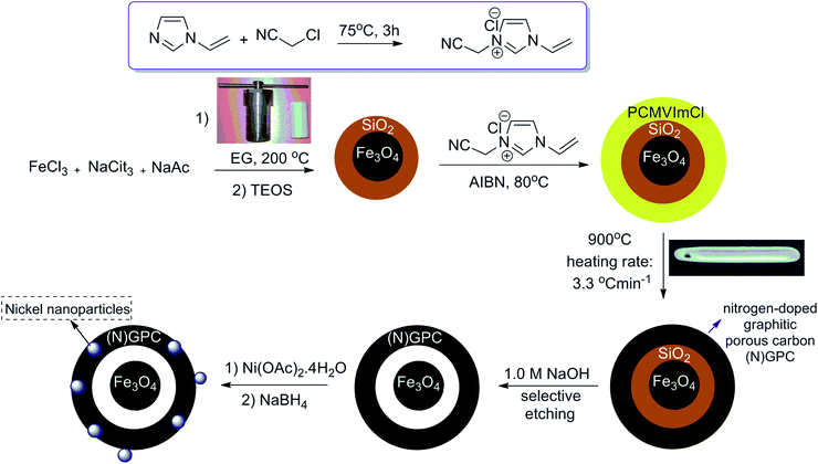
Fe3O4@SiO2 particles were synthesized with a modified solvothermal reaction, followed by a sol–gel process. Then, the poly(3-cyanomethyl-1-vinylimidazolium chloride) (PCMVImCl) layer was coated on the prepared particles via the polymerization of the IL monomer in ethanol. Pyrolysis of Fe3O4@SiO2@poly(imidazolium-based)ILs, allowed the preparation of magnetic nitrogen-doped graphitic porous carbon ((N)-GPC) materials in general. Then, the SiO2 middle layer was removed by a selective etching process to obtain hollow structures. Finally, nickel nanoparticles immobilized on YS Fe3O4@PIL-D-(N)GPC were synthesized by introducing Ni2+ ions, which interact well with the nitrogen groups of the support, and subsequently their reduction with sodium borohydride (Scheme 1).The supported catalyst was employed for the tandem dehydrogenation of sodium borohydride and hydrogenation of nitro/nitrile compounds. A plausible mechanism for this reaction catalyzed by NiNPs@YS Fe3O4@PIL-D-(N)GPC has been shown in Scheme 2. The chemical modification of the adsorbent surface with nitrogen based functional groups or other heteroatom and transition metal doping increases the binding energy states of H2.42 On the other hand, in aqueous media the organic substrates are concentrated on the hydrophobic pores of graphitic porous carbon. In our catalytic system, these three issues are combined; substrates, H2 and catalyst, all of which are in the hydrophobic pores of graphitic porous carbon. Thus, it is expected that an efficient catalytic reaction would be achieved. Fourier transform infrared (FTIR) spectra of Fe3O4 magnetic particles, and Fe3O4@SiO2 are shown in Fig. S1.† Fig. 1A–C show the FTIR spectra of Fe3O4@SiO2@PCMVImCl, Fe3O4@SiO2@PIL-D-(N)GPC, and YS Fe3O4@PIL-D-(N)GPC, respectively. The FTIR spectrum of Fe3O4@SiO2@PCMVImCl (Fig. 1A) shows absorption bands at 576 cm−1 and 3431 cm−1 ascribed to the Fe–O and O–H vibrations, respectively. Moreover, the band at 1091 cm−1 related to Si–O–Si stretching vibrations of SiO2 shell can be seen. The adsorption peaks at 3144 and 2926 cm−1 can be assigned as the C–H stretching vibrations of the imidazole ring and the alkyl chains.
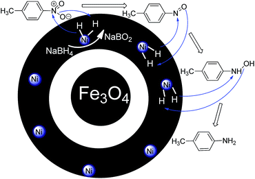 | ||
| Scheme 2 A plausible mechanism for the tandem dehydrogenation of sodium borohydride and reduction of 4-nitrotoluene catalyzed by NiNPs@YS Fe3O4@PIL-D-(N)GPC. | ||
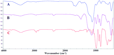 | ||
| Fig. 1 FT-IR spectra of Fe3O4@SiO2@PCMVImCl (A), Fe3O4@SiO2@PIL-D-(N)GPC (B), and YS Fe3O4@PIL-D-(N)GPC (C). | ||
The stretching vibrations belonging to the C–N of the imidazole rings, which should appear at 1138 cm−1, was overlapped with the band at 1091 cm−1 related to Si–O–Si. The peak at about 1633 cm−1 is related to the C![[double bond, length as m-dash]](https://www.rsc.org/images/entities/char_e001.gif) N stretching vibration of the imidazole ring. FTIR spectrum of Fe3O4@SiO2@PIL-D-(N)GPC is shown in Fig. 1B. The weak band at 3442 cm−1 can be attributed to the N–H symmetric stretching vibration.43 The band at 2925 cm−1 corresponds to the C–H stretching vibration. The broad peak around 1259 cm−1 is related to the C–N stretching vibration, which is overlapped with the peak of Si–O–Si in the FTIR spectrum of Fe3O4@SiO2@PIL-D-(N)GPC, but observable in the spectrum of YS Fe3O4@PIL-D-(N)GPC.44 Therefore, the FTIR analysis confirms the presence of N–H and C–N species in the ensuing porous carbon. In the FTIR spectrum of YS Fe3O4@PIL-D-(N)GPC (Fig. 1C), the adsorption peak of Si–O–Si at 1099 cm−1 was not observed, which confirmed the successful elimination of the middle SiO2 layer.
N stretching vibration of the imidazole ring. FTIR spectrum of Fe3O4@SiO2@PIL-D-(N)GPC is shown in Fig. 1B. The weak band at 3442 cm−1 can be attributed to the N–H symmetric stretching vibration.43 The band at 2925 cm−1 corresponds to the C–H stretching vibration. The broad peak around 1259 cm−1 is related to the C–N stretching vibration, which is overlapped with the peak of Si–O–Si in the FTIR spectrum of Fe3O4@SiO2@PIL-D-(N)GPC, but observable in the spectrum of YS Fe3O4@PIL-D-(N)GPC.44 Therefore, the FTIR analysis confirms the presence of N–H and C–N species in the ensuing porous carbon. In the FTIR spectrum of YS Fe3O4@PIL-D-(N)GPC (Fig. 1C), the adsorption peak of Si–O–Si at 1099 cm−1 was not observed, which confirmed the successful elimination of the middle SiO2 layer.
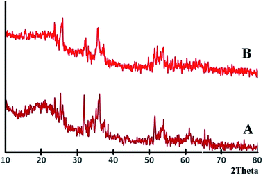
The XRD patterns of Fe3O4@SiO2, and Fe3O4@SiO2@PCMVImCl are presented in Fig. S2.† In the XRD pattern of Fe3O4@SiO2@PIL-D-(N)GPC (Fig. 2A), in addition to the characteristic diffraction peaks of Fe3O4 at 2θ = 32.14°, 35.57°, 51.34°and a broad peak at around 2θ = 20.12°, which corresponds to SiO2, a wide diffraction peak at around 2θ = 25.63° is also observed, which relates to the (002) plane of graphitic mesoporous carbon. In the XRD pattern of the YS Fe3O4@PIL-D-(N)GPC (Fig. 2B), the peak of silica at 20.12° is eliminated as expected, due to the removing of silica intermediate shell.
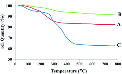
Fig. 3A–C show the thermograms (TGs) of three samples: Fe3O4, Fe3O4@SiO2, and Fe3O4@SiO2@PCMVImCl, respectively. Compared to the TGA diagram of Fe3O4@SiO2 particles, the considerably higher weight loss observed in the TGA diagram of Fe3O4@SiO2@PCMVImCl is from the organic decomposition of the composites. Before thermal decomposition a slight weight loss of around 5.2% is observed, as shown in Fig. 3C. This weight loss is probably due to the evaporation of physically absorbed moisture, and its value is a little higher in the Fe3O4@SiO2@PCMVImCl composite particles compared to Fe3O4@SiO2, which is caused by the high hydrophilicity of the PCMVImCl shell. Fe3O4@SiO2 clearly shows two types of distinct weight loss events: successive rapid decompositions at 140 °C and 260 °C due to the decomposition of the organic shell vs. the relatively slow weight loss region at around 520–700 °C due to the intermolecular condensation of the silica particles. The weight retention obtained for Fe3O4@SiO2@PCMVImCl (Fig. 3C) at 780 °C is 62.9%. Using the weight retention at 780 °C obtained for Fe3O4@SiO2 (91.2%) as a reference, the PCMVImCl weight content is calculated to be 28.3%. Two rapid thermal degradation events of Fe3O4@SiO2@PCMVImCl occur at 283, and 374 °C under air atmosphere, which are due to the cleavage of the PCMVImCl polymer backbone (or carbonation).
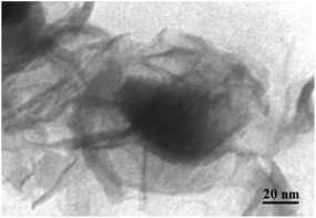
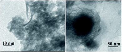
The TEM image of YS Fe3O4@PIL-D-(N)GPC is presented in Fig. 4, which shows Fe3O4 magnetic particles coated with a folded, lamellar-like morphology of stiff graphite plates with the curved and wrapped structure. As clearly revealed, the lamellar-like structures are, in fact, layered graphitic nanostructures. Fig. 5 shows TEM images of NiNPs@YS Fe3O4@PIL-D-(N)GPC in which three distinct components the black cores of Fe3O4, the grey shells of graphite plates and the small black spheres of nickel nanoparticles are observed.
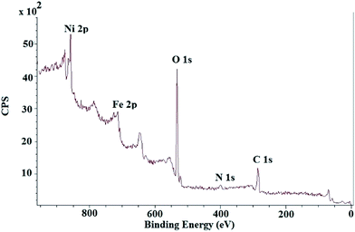
The XPS spectrum of NiNPs@YS Fe3O4@PIL-D-(N)GPC possesses four peaks centered at 284.7, 400.1, 530.9, and 711.4 eV, corresponding to C 1s, N 1s, O 1s, and Fe 2p, respectively (Fig. 6). The oxygen mainly arises from Fe3O4 and the thermally stable groups in the carbon except for that of oxygen or water absorbed on the carbon surface. The high-resolution XPS of N 1s in the NiNPs@YS Fe3O4@PIL-D-(N)GPC shows two peaks for N1s at 398.7 eV and 401.3 eV, which are attributed to pyridinic and quaternary nitrogen in carbon structure, respectively (Fig. 7A). These two different binding energies show that nitrogen is embedded into the graphitic carbon structure mainly in two forms.45 The spectrum of the Ni2p core level of NiNPs@YS Fe3O4@PIL-D-(N)GPC is shown in Fig. 7B, which demonstrates two bands at 855.9 and 873.5 eV assigned to Ni02p3/2 and Ni02p1/2, respectively. The two peaks with lower intensities at 861.7 and 879.5 eV correspond to Ni2+ species that could have been formed during the XPS sample preparation due to the sensitivity of the stabilized Ni(0) nanoclusters to the aerobic atmosphere. The Ni loading for the sample used for XPS measurements was 9.8 wt%. Moreover, the absence of silicon band at around 104 eV confirms the selective etching of silica shell.
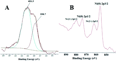 | ||
| Fig. 7 XPS high-resolution spectra of the N 1s (A) and Ni 2p (B) of the as-prepared NiNPs@YS Fe3O4@PIL-D-(N)GPC. | ||
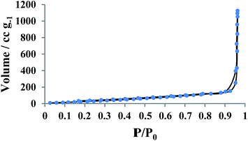
Fig. 8 shows the nitrogen adsorption–desorption isotherms recorded from YS Fe3O4@PIL-D-(N)GPC. The results showed that the average pore sizes are 2.5 nm and by applying the BET model, the total surface area is calculated to be 138.63 m2 g−1. BET testing also showed a pore structure consisting of micropores, and mesopores. The pore size distribution curve has been shown in Fig. S3.†
Catalytic hydrolysis of sodium borohydride can generate 4 mol of hydrogen per mol of sodium borohydride at room temperature, which in itself, is a useful approach for hydrogen release from sodium borohydride (hydrogen content of 10.7 wt%).46
On the other hand, theoretical and also experimental studies have established that substitutional doping of carbon materials can be employed to modify their physical and/or chemical properties and also affect the hydrogen adsorption and desorption process.47 A modification approach of base activation,48,49 (N-doped structure), transition-metal catalysts,46,50 (NiNPs), and nanoscaffolds46,51 by NiNPs@YS Fe3O4@PIL-D-(N)GPC allows sodium borohydride to release 4 mol of H2 in aqueous solution at room temperatures.
Our investigation on the catalyst loading showed a high atom efficiency of title NiNPs@YS Fe3O4@PIL-D-(N)GPC. We first used 4-nitrotoluene as a model compound to demonstrate NiNPs@YS Fe3O4@PIL-D-(N)GPC catalysis for the tandem dehydrogenation of sodium borohydride, the hydrogenation of nitro compounds and to obtain the optimum reaction conditions. We examined the catalytic reactions at room temperature in different solvents including DMSO, methanol, ethanol, water, and determined water to be the best solvent to convert 4-nitrotoluene to p-toluidine. Actually, because of the hydrophobic nature of porous carbon, the reactants tend to collect at those sites rather than water solvent. On the other hand, nickel nanoparticles as catalyst and hydrogen also exist in the pores. Thus, an efficient catalytic reaction probably occurs as the reagents and catalyst concentrate in an area. Moreover, to optimize the amount of the catalyst, different amounts of the catalyst, including 0.8, 1, and 1.2 mol% Ni were used for model reaction in water at room temperature. The optimum amount of the catalyst considering the reaction time and yield was 1 mol%. In addition, the model reaction was carried out without catalyst in which no product was obtained over 24 h. According to these results, the optimum reaction condition is water as solvent and 1 mol% Ni for the NiNPs@YS Fe3O4@PIL-D-(N)GPC to catalyze the tandem reaction. The summary of these results are given in Table S1.†
We also studied the support effect on nickel nanoparticles catalysis. Nickel nanoparticles were used as active catalysts without a support in a model reaction for the catalytic reduction of 4-nitrotoluene, but the conversion yield was low (33%). It could be due to the aggregation of nickel nanoparticles without a support, resulting in reduced catalytic activity. The improvement of the results with the support could be due to π–π interactions of the aromatic groups in reactants with the support preferring the close proximity of the reagents to the catalytic sites.
To evaluate the general applicability of the catalyst, different nitro compounds were tested for reduction reaction using sodium borohydride and 0.006 g catalyst containing 1 mol% Ni at 25 °C in water (Table 1). The 1H NMR spectra of the products have been presented in Fig. S4–10.† As can be seen, various nitro compounds can generate the related amine in excellent yields. The catalytic reaction could be extended to 1-methoxy-4-nitrobenzene, 1-nitronaphthalene, 1-fluoro-4-nitrobenzene, 1-iodo-3-nitrobenzene, 1-bromo-4-nitrobenzene, and also nitroethane compounds, which were all transformed to the respective amine derivatives with high yields (Table 1, entries 2−7). Moreover, with respect to general applicability of the catalyst NiNPs@YS Fe3O4@PIL-D-(N)GPC, we also tested the reduction reaction of nitrile compounds to the corresponding amines and the results are shown in Table 1, entries 8–10. The reduction of benzonitriles is an important issue because it allows the easy preparation of a variety of biologically active benzyl amines compounds. Moreover, the reduction reaction of picolinonitrile was examined, which resulted in the related amine in high yield (Table 1, entry 9). The 1H NMR spectra of the products are shown in Fig. S11–13.†
| Entry | Compound | Product | Time (min) | Isolated yield (%) |
|---|---|---|---|---|
| a Reaction conditions: 5 mL of deionized water, 1 mmol nitro/nitrile, 0.5 mmol NaBH4, and 0.006 g catalyst at 25 °C. | ||||
| 1 |  |
 |
30 | 90 |
| 2 |  |
 |
30 | 91 |
| 3 |  |
 |
30 | 87 |
| 4 |  |
 |
25 | 92 |
| 5 |  |
 |
30 | 90 |
| 6 |  |
 |
30 | 90 |
| 7 |  |
 |
30 | 88 |
| 8 |  |
 |
60 | 89 |
| 9 |  |
 |
60 | 80 |
| 10 |  |
 |
45 | 87 |
As catalysis is a kinetic phenomenon, to investigate the recyclability and deactivation of the catalyst, the initial rates obtained from kinetic plots should be considered. If a single data point after long reaction time in each run was taken, one might incorrectly conclude that the catalyst is completely stable and recyclable.52 Therefore, the conversion yields for every run after 10 min for the reduction reaction of 4-nitrotoluene were measured (Fig. 9A). As the conversion yields after 10 min for seven runs did not reduce considerably, we concluded that the synthesized catalyst had good stability and recyclability. To examine the productivity of the as-prepared catalyst, we investigated the reduction reaction of 4-nitrotoluene as a model reaction up to seven cycles after the completion of the reaction. By design, the magnetic extraction excludes the need for filtration, centrifugation or the workup of the final reaction mixture to recover the catalyst, and consequently allows the easy recycling of the catalyst. The results have been presented in Fig. 9B, which indicates that the yield of product after every run does not change significantly.
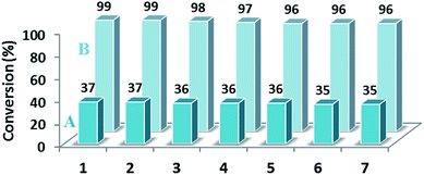 | ||
| Fig. 9 Effect of recycling on the catalytic activity and productivity of NiNPs@YS Fe3O4@PIL-D-(N)GPC after 10 (A) and after 30 min (B). | ||
Conclusion
In this work, we have achieved several important aims: (i) having a heterogeneous catalyst with the advantage of being efficient, reusable, cost-effective and also removing the need for the catalyst filtration with magnetic separation; (ii) having a yolk–shell structure with unique properties such as large surface area, multi-functionality and excellent loading capacity; (iii) employing porous carbon as stabilizer for nanoparticles, which has several important advantages such as large surface area, stability, and straightforward synthesis; (iv) using poly(ionic liquid)s as precursor for the synthesis of nitrogen doped porous carbon; (v) carrying out the tandem reaction in an environmentally friendly and safe method; (vi) having the catalytic activity for reduction of nitro and nitrile compounds with high yields.Experimental
Materials
1-Vinylimidazole, and chloroacetonitrile were obtained from Sigma-Aldrich and used without further purification. 2,2′-Azobis(2-methylpropionitrile) (AIBN) (Aldrich) was recrystallized from methanol. CMVImCl as IL monomer was prepared according to the literature,53 and its 1H NMR spectrum is presented in Fig. S14.† Nickel(II) acetate tetrahydrate was purchased from Alfa Aesar. Ferric chloride hexahydrate (FeCl3·6H2O), trisodium citrate dehydrate (Na3Cit·2H2O), sodium acetate (NaAc), ethylene glycol (EG), tetraethyl orthosilicate (TEOS), and sodium hydroxide (NaOH) were purchased from Merck Chem. Toluene was dried from sodium. Dichloromethane and methanol were dried from calcium hydride and magnesium, respectively. All other solvents and reagents were purchased from Aldrich or Merck and used without further purification unless otherwise stated.Instruments and characterization
IR spectra were recorded on a Bomem MB-Series FTIR spectrophotometer. Transmission electron microscopy (TEM) analyses were performed using a LEO 912AB electron microscope. Ultrasonic bath (EUROSONIC® 4D ultrasound cleaner with a frequency of 50 kHz and an output power of 350 W) was used to disperse materials in solvents. Thermogravimetric analysis (TGA) was carried out using STA 1500 instrument at a heating rate of 10 °C min−1 in air. The specific surface area was calculated using the Brunauer–Emmett–Teller (BET) equation. Pore size distribution was determined by the Barrett–Joyner–Halenda (BJH) method. The samples were degassed at 150 °C for 20 h before measurements. X-ray powder diffraction (XRD) data were collected on an XD-3A diffractometer using Cu Kα radiation. XPS analysis was performed using a VG multilab 2000 spectrometer (ThermoVG scientific) in an ultrahigh vacuum. Catalysis products were analyzed using a Varian 3900 gas chromatograph (GC) (conversions were obtained using n-decane as an internal standard). AA-680 Shimadzu (Kyoto, Japan) flame atomic absorption spectrometer (AAS) with a deuterium background corrector was used for the determination of the metal. 1H NMR spectra were recorded with a BRUKER DRX-300 AVANCE spectrometer, and DMSO or CDCl3 were used as solvents.Synthesis and coating of Fe3O4 with silica (Fe3O4@SiO2)
Fe3O4 nanoclusters were synthesized according to the literature.54 Typically, FeCl3 (0.65 g, 4.0 mmol) and trisodium citrate (0.20 g, 0.68 mmol) were first dissolved in ethylene glycol (20 mL). Next, NaAc (1.20 g) was added with stirring. The mixture was vigorously stirred for 30 min, and then sealed in a Teflon-lined stainless-steel autoclave. The autoclave was heated to 200 °C, maintained for 10 h, and then allowed to cool to room temperature. The obtained Fe3O4 particle suspension was successively washed three times with H2O and EtOH, and then dried in a vacuum oven for 12 h at room temperature. For the coating of Fe3O4 with silica, 50.0 mL of the as-prepared Fe3O4 nanocluster solution (containing 0.4 g Fe3O4) was dispersed into the mixture of deionized water (10.0 mL), ethanol (100.0 mL) and NH3·H2O (50.0 mL). After ultrasound treatment for 10 min, a certain amount of TEOS was quickly added into the system. The reaction was allowed to proceed with stirring for 8 h at room temperature. Finally the products were separated by magnet and washed using deionized water for the next-step.Preparation of Fe3O4/SiO2/PILs composite particles (Fe3O4@SiO2@PCMVImCl)
The PIL layer on silica particles was synthesized via polymerization of IL monomer in the presence of Fe3O4@SiO2 particles in ethanol. In a general polymerization procedure, 3 g of CMVImCl monomer, 200 mg of AIBN and 5 mL of deionized water were added to 70 mL of ethanol containing 3 g of dispersed Fe3O4@SiO2 particles. The dispersion was degassed by purging with nitrogen for 30 min prior to polymerization. The polymerization was conducted with vigorous stirring overnight at 80 °C. After cooling down, the obtained Fe3O4@SiO2@PCMVImCl composite particles were washed by four centrifugation/redispersion cycles with deionized water, and dried at 60 °C under vacuum.Carbonization process
In a typical experiment, the dried Fe3O4@SiO2@PCMVImCl sample was put into an aluminum oxide crucible in an oven and heated under a N2 atmosphere to 900 °C at a heating rate of 3.3 °C min−1. The sample was further maintained at 900 °C for 1 h and slowly cooled down to room temperature.Preparation of the yolk/shell Fe3O4@poly(ionic liquid)s-derived nitrogen-doped graphitic porous carbon materials (YS Fe3O4@PIL-D-(N)GPC)
Fe3O4@poly(ionic liquid)s-derived nitrogen-doped graphitic porous carbon materials were soaked in 1.0 M NaOH solution with mechanical stirring for 12.0 h; the SiO2 layer between the carbon shell and the Fe3O4 core was selectively etched. After washing several times with deionized water and ethanol, the black product was dried overnight in oven.Synthesis of nickel nanoparticles immobilized on YS Fe3O4@PIL-D-(N)GPC (NiNPs@YS Fe3O4@PIL-D-(N)GPC)
Aqueous solutions of nickel(II) acetate tetrahydrate (0.01 mL, 0.15 M) and YS Fe3O4@PIL-D-(N)GPC (0.1 g in 10 mL) were mixed and placed in an ultrasonic bath (50 kHz) for 10 min to well disperse metal ions in the hybrid material. Mixture was stirred at room temperature for 8 h, and then reduction was carried out with the addition of 0.5 mL aqueous solution of NaBH4 (0.01 M) to the mixture and stirring at room temperature for 1 h. It was filtered under vacuum, washed well with ethanol and water (2 × 20 mL) and dried under vacuum at 50 °C for 4 h to obtain NiNPs@YS Fe3O4@PIL-D-(N)GPC. The AAS and TGA were used to determine the amount of nickel in the synthesized catalyst.General procedure for the tandem dehydrogenation of sodium borohydride and hydrogenation of nitro/nitrile compounds with NiNPs@YS Fe3O4@PIL-d-(N)GPC as catalyst
To 2 mL distilled water, 1 mmol nitro/nitrile was added and into this solution 0.006 g ultrasonically dispersed NiNPs@YS Fe3O4@PIL-d-(N)GPC catalyst (1 mol% Ni) in water (3.0 mL) was introduced. Finally, 0.5 mmol NaBH4 (0.038 g) was introduced. The mixture was stirred. After the completion of the reaction, the catalyst was removed via an external magnetic field and washed twice with CH2Cl2 (6.0 mL). Then, the organic phase was combined and the solvent was removed under vacuum to obtain the pure product. The conversions were determined by the gas chromatography (GC) analysis.Acknowledgements
The financial support provided by the Iran National Science Foundation (INSF) is gratefully acknowledged.Notes and references
- R. Güttel, M. Paul and F. Schüth, Catal. Sci. Technol., 2011, 1, 65–68 Search PubMed.
- C. C. Yec and H. C. Zeng, Chem. Mater., 2012, 24, 1917–1929 CrossRef CAS.
- Y. Chen, Y. Gao, H. Chen, D. Zeng, Y. Li, Y. Zheng, F. Li, X. Ji, X. Wang and F. Chen, Adv. Funct. Mater., 2012, 22, 1586–1597 CrossRef CAS.
- T. Yang, J. Liu, Y. Zheng, M. J. Monteiro and S. Z. Qiao, Chem.–Eur. J., 2013, 19, 6942–6945 CrossRef CAS PubMed.
- Y. Chen, H. Chen, M. Ma, F. Chen, L. Guo, L. Zhang and J. Shi, J. Mater. Chem., 2011, 21, 5290–5298 RSC.
- H. Wu, G. Liu, S. Zhang, J. Shi, L. Zhang, Y. Chen, F. Chen and H. Chen, J. Mater. Chem., 2011, 21, 3037–3045 RSC.
- J. Lee, J. Kim and T. Hyeon, Adv. Mater., 2006, 18, 2073–2094 CrossRef CAS.
- J. Zeng, F. Su, Y.-F. Han, Z. Tian, C. K. Poh, Z. Liu, J. Lin, J. Y. Lee and X. Zhao, J. Phys. Chem. C, 2008, 112, 15908–15914 CAS.
- J. Zeng, F. Su, J. Y. Lee, X. Zhao, J. Chen and X. Jiang, J. Mater. Sci., 2007, 42, 7191–7197 CrossRef CAS PubMed.
- Y. Wang, F. Su, J. Y. Lee and X. Zhao, Chem. Mater., 2006, 18, 1347–1353 CrossRef CAS.
- R. Pietrzak, H. Wachowska and P. Nowicki, Energy Fuels, 2006, 20, 1275–1280 CrossRef CAS.
- F. Jaouen, M. Lefevre, J. Dodelet and M. Cai, J. Phys. Chem. B, 2006, 110, 5553–5558 CrossRef CAS PubMed.
- L. Li, E. Liu, Y. Yang, H. Shen, Z. Huang and X. Xiang, Mater. Lett., 2010, 64, 2115–2117 CrossRef CAS PubMed.
- P. Matter, L. Zhang and U. Ozkan, J. Catal., 2006, 239, 83–96 CrossRef CAS PubMed.
- M. Titirici, R. White, C. Falco and M. Sevilla, Energy Environ. Sci., 2012, 5, 6796–6822 Search PubMed.
- M. Sevilla and A. Fuertes, Chem.–Eur. J., 2009, 15, 4195–4203 CrossRef CAS PubMed.
- F. Braghiroli, V. Fierro, M. Izquierdo, J. Parmentier, A. Pizzi and A. Celzard, Carbon, 2012, 50, 5411–5420 CrossRef CAS PubMed.
- J. P. Paraknowitsch, J. Zhang, D. Su, A. Thomas and M. Antonietti, Adv. Mater., 2010, 22, 87–92 CrossRef CAS PubMed.
- M. Antonietti, D. Kuang, B. Smarsly and Y. Zhou, Angew. Chem., Int. Ed., 2004, 43, 4988–4992 CrossRef CAS PubMed.
- R. Czerw, M. Terrones, J.-C. Charlier, X. Blase, B. Foley, R. Kamalakaran, N. Grobert, H. Terrones, D. Tekleab and P. Ajayan, Nano Lett., 2001, 1, 457–460 CrossRef CAS.
- K. K. Datta, V. V. Balasubramanian, K. Ariga, T. Mori and A. Vinu, Chem.–Eur. J., 2011, 17, 3390–3397 CrossRef CAS PubMed.
- K. Gong, F. Du, Z. Xia, M. Durstock and L. Dai, Science, 2009, 323, 760–764 CrossRef CAS PubMed.
- Y.-H. Li, T.-H. Hung and C.-W. Chen, Carbon, 2009, 47, 850–855 CrossRef CAS PubMed.
- A. Zamudio, A. L. Elías, J. A. Rodríguez-Manzo, F. López-Urías, G. Rodríguez-Gattorno, F. Lupo, M. Rühle, D. J. Smith, H. Terrones and D. Díaz, Small, 2006, 2, 346–350 CrossRef CAS PubMed.
- J. Yuan and M. Antonietti, Macromolecules, 2011, 44, 744–750 CrossRef CAS.
- J. Yuan, C. Giordano and M. Antonietti, Chem. Mater., 2010, 22, 5003–5012 CrossRef CAS.
- J. Yuan, A. G. Márquez, J. Reinacher, C. Giordano, J. Janek and M. Antonietti, Polym. Chem., 2011, 2, 1654–1657 RSC.
- J. Yuan, H. Schlaad, C. Giordano and M. Antonietti, Polym. Chem., 2011, 47, 772–781 CAS.
- X. Bo, J. Bai, J. Ju and L. Guo, J. Power Sources, 2011, 196, 8360–8365 CrossRef CAS PubMed.
- J. Yuan, S. Soll, M. Drechsler, A. H. Müller and M. Antonietti, J. Am. Chem. Soc., 2011, 133, 17556–17559 CrossRef CAS PubMed.
- M. R. Nabid and S. J. Tabatabaei Rezaei, Appl. Catal., A, 2009, 366, 108–113 CrossRef CAS PubMed.
- M. R. Nabid, Y. Bide, N. Ghalavand and M. Niknezhad, Appl. Organomet. Chem., 2014, 28, 389–395 CrossRef CAS.
- M. R. Nabid, Y. Bide, E. Aghaghafari and S. Rezaei, Catal. Lett., 2014, 144, 355–363 CrossRef CAS PubMed.
- M. R. Nabid and Y. Bide, Appl. Catal., A, 2014, 469, 183–190 CrossRef CAS PubMed.
- M. R. Nabid, Y. Bide and M. Abuali, RSC Adv., 2014, 4, 35844–35851 RSC.
- M. R. Nabid, Y. Bide and S. J. Tabatabaei Rezaei, Appl. Catal., A, 2011, 406, 124–132 CrossRef CAS PubMed.
- M. R. Nabid, Y. Bide and M. Niknezhad, ChemCatChem, 2014, 6, 538–546 CrossRef CAS.
- F. Alonso, P. Riente and M. Yus, Tetrahedron, 2008, 64, 1847–1852 CrossRef CAS PubMed.
- T. Li, W. Zhang, R. Z. Lee and Q. Zhong, Food Chem., 2009, 114, 447–452 CrossRef CAS PubMed.
- M. J. Gracia, J. M. Campelo, E. Losada, R. Luque, J. M. Marinas and A. A. Romero, Org. Biomol. Chem., 2009, 7, 4821–4824 CAS.
- L. Znak and J. Zieliński, Appl. Catal., A, 2008, 334, 268–276 CrossRef CAS PubMed.
- V. B. Parambhath, R. Nagar and S. Ramaprabhu, Langmuir, 2012, 28, 7826–7833 CrossRef CAS PubMed.
- G. Socrates, Infrared and Raman characteristic group frequencies: tables and charts, John Wiley & Sons, 2004 Search PubMed.
- H. Blaser, A. Baiker and R. Prins, Heterogeneous catalysis and fine chemicals IV, Elsevier, 1997 Search PubMed.
- T.-P. Fellinger, A. Thomas, J. Yuan and M. Antonietti, Adv. Mater., 2013, 25, 5838–5855 CrossRef CAS PubMed.
- O. Metin and S. Ozkar, Energy Fuels, 2009, 23, 3517–3526 CrossRef CAS.
- E. Paleček, M. Bartošík, V. Ostatná and M. Trefulka, Chem. Rec., 2012, 12, 27–45 CrossRef PubMed.
- D. W. Himmelberger, C. W. Yoon, M. E. Bluhm, P. J. Carroll and L. G. Sneddon, J. Am. Chem. Soc., 2009, 131, 14101–14110 CrossRef CAS PubMed.
- A. Levy, J. B. Brown and C. J. Lyons, Ind. Eng. Chem. Res., 1960, 52, 211–214 CrossRef CAS.
- B. H. Liu, Z. P. Li and S. Suda, J. Alloys Compd., 2006, 415, 288–293 CrossRef CAS PubMed.
- A. Gutowska, L. Li, Y. Shin, C. M. Wang, X. S. Li, J. C. Linehan, R. S. Smith, B. D. Kay, B. Schmid and W. Shaw, Angew. Chem., Int. Ed., 2005, 44, 3578–3582 CrossRef CAS PubMed.
- C. W. Jones, Top. Catal., 2010, 53, 942–952 CrossRef CAS.
- J. Wang, Y. Li, P. Li and G. Song, Monatsh. Chem., 2013, 144, 1159–1163 CrossRef CAS.
- J. Liu, Z. Sun, Y. Deng, Y. Zou, C. Li, X. Guo, L. Xiong, Y. Gao, F. Li and D. Zhao, Angew. Chem., Int. Ed., 2009, 48, 5875–5879 CrossRef CAS PubMed.
Footnote |
| † Electronic supplementary information (ESI) available. See DOI: 10.1039/c4ra10374b |
| This journal is © The Royal Society of Chemistry 2015 |

