A soil/Vulcan XC-72 hybrid as a highly-effective catalytic cathode for rechargeable Li–O2 batteries†
Xiaofei
Hu
a,
Xiaorui
Fu
a and
Jun
Chen
*ab
aKey Laboratory of Advanced Energy Materials Chemistry (Ministry of Education), Nankai University, Tianjin, 300071, People's Republic of China. E-mail: chenabc@nankai.edu.cn; Fax: +86-22-23506808; Tel: +86-22-23506808
bCollaborative Innovation Center of Chemical Science and Engineering, Nankai University, Tianjin, 300071, People's Republic of China
First published on 10th September 2015
Abstract
We report for the first time a hybrid of soil and commercial Vulcan XC-72 carbon (labeled as soil/C) as a high-performance cathode catalyst for rechargeable lithium–oxygen batteries. A one-step mixing at room temperature is used to synthesize the soil/C hybrid, in which soil particles (0.5–5 μm) play a role of void volume expanders (VVE) so that the Vulcan XC-72 carbon (∼100 nm) area is fully exposed for the deposition of the discharge product. Meanwhile, the outer & inner catalytic sites of carbon particles are sufficiently utilized. When used as a cathode catalyst for rechargeable lithium–oxygen batteries, the soil/C hybrid exhibits a large discharge capacity (7640 mA h g−1), robust cyclability (100 cycles at 0.2 mA cm−2) and superior rate capability. This high performance is not inferior to noble metal containing catalysts. Therefore, soil as a low cost and metal-free VVE in the soil/C hybrid catalyst is promising in the application of rechargeable Li–O2 batteries.
Introduction
Nonaqueous rechargeable Li–O2 batteries have recently drawn worldwide attention owing to their relatively high theoretical energy density of 3500 Wh per kg of Li2O2, which is comparable to the available energy density of gasoline (including consumed oxygen).1 This high electrochemical performance relies on their cathode catalysts that are able to accelerate the inherently sluggish kinetics of the oxygen reduction reaction (ORR, 2Li+ + O2 + 2e− → Li2O2) and the oxygen evolution reaction (OER, Li2O2 → 2Li+ + O2 + 2e−).2Among various cathode catalysts of Li–O2 batteries, carbon-based materials such as vertically aligned N-doped coral-like carbon fiber arrays,3 ordered mesoporous carbon,4 Co–N-multiwalled-CNTs,5 hierarchical mesoporous/macroporous carbon,6 and graphene/graphene-tube nanocomposites7 have displayed characteristics of relatively low cost and considerable catalytic activity. Their large specific areas provide extended deposition space for the discharge product of Li2O2. More importantly, the large specific area also easily exposes abundant catalytic sites for accelerating the sluggish kinetics of ORR and OER. Different from the above unique carbon-based materials with exotic structures, commercial carbon materials such as Vulcan XC-72, super S, and super P are produced on a large scale and are relatively cheap. Commercial carbon materials such as Vulcan XC-72 have always been used as conductive addition to overcome the poor conductivity of metal oxide or nitride catalysts in air cathode.2c,8 Meanwhile, commercial carbon materials suffer from disadvantages when solely used as Li–O2 battery cathode catalysts, e.g. low capacity and poor cyclability, resulting from fast surficial passivation from uneven deposition of the discharge product (Li2O2).9 Therefore, it is necessary to improve the electrocatalytic performance of commercial carbon by a simple way and enable them to play the leading role of a cathode catalyst for rechargeable Li–O2 batteries.
From the standpoint of suppressing surficial passivation of the carbon cathode, it is worth trying to construct a hybrid catalyst by mixing commercial carbon (labeled as C) with inactive species. Herein, we call these inactive species (such as soil particles) as void volume expanders (VVE). Undoubtedly, it is of low-cost and easily scaled up to fabricate a soil/C hybrid catalyst, in which, the carbon species would be separated by soil particles to expose more area and catalytic sites for enlarging capacity and accelerating battery reactions.
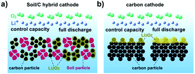
In this paper, we demonstrate the first use of soil as a VVE to construct a soil/C hybrid as the cathode catalyst for rechargeable Li–O2 batteries. Commercial Vulcan XC-72 carbon (∼100 nm) separated by soil particles (0.5–5 μm) would expose more areas that carry active sites. These extended areas benefit the scattered deposition of insoluble and hardly conductive Li2O2 during the discharge, and correspondingly suppress fast passivation of the carbon cathode. In addition, it is hard for Li2O2 to deposit on inactive particles so that the voids of these particles open channels for free transfer of O2 and Li+ during the discharge/charge process (Scheme 1a and b). When the mass ratio between Vulcan XC-72 and soil is 10![[thin space (1/6-em)]](https://www.rsc.org/images/entities/char_2009.gif) :
:![[thin space (1/6-em)]](https://www.rsc.org/images/entities/char_2009.gif) 1, the hybrid assisted Li–O2 batteries (CR2032 coin-type) exhibited 7640 mA h g−1 capacity at 0.2 mA cm−2, which is comparable to noble metal containing catalysts. Even at 1.0 mA cm−2 the hybrid based batteries still showed the capacity of 2000 mA h g−1. Such batteries presented excellent cyclability of 100 cycles at 0.2 mA cm−2 with fixed 800 mA h g−1 (0.4 mA h cm−2).
1, the hybrid assisted Li–O2 batteries (CR2032 coin-type) exhibited 7640 mA h g−1 capacity at 0.2 mA cm−2, which is comparable to noble metal containing catalysts. Even at 1.0 mA cm−2 the hybrid based batteries still showed the capacity of 2000 mA h g−1. Such batteries presented excellent cyclability of 100 cycles at 0.2 mA cm−2 with fixed 800 mA h g−1 (0.4 mA h cm−2).
Experimental section
Material synthesis and characterization
Collected soil was first calcined at 700 °C for 2 h and further ball milled at 300 rpm for 20 h. The structures of the pristine and treated soil were characterized by X-ray diffraction (XRD, Rigaku MiniFlex600, Cu Kα radiation). The morphologies of raw materials and electrodes were observed by field-emission scanning electron microscopy (SEM, JEOL JSM7500F).Electrochemical test
Electrochemical performance of Li–O2 batteries was tested via CR2032 coin-type batteries. The cathodes were prepared by blending Vulcan XC-72 carbon (labeled as C), treated soil, and polyvinylidene fluoride (PVdF) in N-methyl-2-pyrrolidone (NMP) with a mass ratio of 82![[thin space (1/6-em)]](https://www.rsc.org/images/entities/char_2009.gif) :
:![[thin space (1/6-em)]](https://www.rsc.org/images/entities/char_2009.gif) 8
8![[thin space (1/6-em)]](https://www.rsc.org/images/entities/char_2009.gif) :
:![[thin space (1/6-em)]](https://www.rsc.org/images/entities/char_2009.gif) 10. The obtained slurries were pasted onto a Ni foam (ø10 mm, 22.6 mg), and dried at 100 °C for 10 hours in air. Li foils (∅14 mm × H0.3 mm) and glass fibers (∅16 mm × H0.3 mm) were used as the anode and the separator, respectively. The electrolyte was 1.0 M lithium bis-(trifluoromethanesulfonyl)-imide (LITFSI) in tetraethylene glycol dimethyl ether (TEGDME). Plastic Li–O2 batteries consisted of one plastic bag filled with a lithium foil anode (14 × 40 × 0.3, mm), a glass fiber separator (16 × 42 × 0.3, mm), and an air electrode (12 × 40, mm, 20 mg of active materials coating on one piece of carbon paper). The cathode side of the plastic bag was punched with many air holes. The electrolyte was 1 M LITFSI in TEGDME. Cyclic voltammograms (CVs) were tested between 2.3 V and 4.2 V at a scan rate of 100 mV s−1. The CV test was carried out on a computer-controlled workstation bipotentiostats (AFCBP1, Pine Instrument). The workstation is assembled with a modulated speed rotator (PHYCHEMI) in a three electrode cell configuration under room temperature. The capacity was based on the area of current collectors (0.785 cm−2) or the total loading mass (∼0.5 mg cm−2) on collectors. The battery performance was tested on a LAND-CT2001A battery-testing system.
10. The obtained slurries were pasted onto a Ni foam (ø10 mm, 22.6 mg), and dried at 100 °C for 10 hours in air. Li foils (∅14 mm × H0.3 mm) and glass fibers (∅16 mm × H0.3 mm) were used as the anode and the separator, respectively. The electrolyte was 1.0 M lithium bis-(trifluoromethanesulfonyl)-imide (LITFSI) in tetraethylene glycol dimethyl ether (TEGDME). Plastic Li–O2 batteries consisted of one plastic bag filled with a lithium foil anode (14 × 40 × 0.3, mm), a glass fiber separator (16 × 42 × 0.3, mm), and an air electrode (12 × 40, mm, 20 mg of active materials coating on one piece of carbon paper). The cathode side of the plastic bag was punched with many air holes. The electrolyte was 1 M LITFSI in TEGDME. Cyclic voltammograms (CVs) were tested between 2.3 V and 4.2 V at a scan rate of 100 mV s−1. The CV test was carried out on a computer-controlled workstation bipotentiostats (AFCBP1, Pine Instrument). The workstation is assembled with a modulated speed rotator (PHYCHEMI) in a three electrode cell configuration under room temperature. The capacity was based on the area of current collectors (0.785 cm−2) or the total loading mass (∼0.5 mg cm−2) on collectors. The battery performance was tested on a LAND-CT2001A battery-testing system.
Rotating-disk-electrode (RDE) measurements
This work employed the RDE technique.10 Briefly, the electrochemical tests were carried out in a glass three-electrode electrochemical cell. It consists of a counter electrode (CE) of lithium foil, a reference electrode (RE) of a KCl-saturated calomel electrode (SCE), and a working electrode (WE) of a glass carbon (GC) electrode, which is coated by a sample and fixed in a rotating ring-disk electrode (RRDE, Pt ring and GC disk, disk radius 2.80 mm). All three electrodes are soaked in 1 M LITFSI electrolyte in TEGDME solution (0 V Li ≈ −3.28 V vs. Hg/Hg2Cl2). The catalyst samples (10 mg) are mixtures of Vulcan XC-72 and treated soil with different mass ratios. The mixtures were ultrasonically dispersed in 1000 mL mixed solvent of 920![[thin space (1/6-em)]](https://www.rsc.org/images/entities/char_2009.gif) :
:![[thin space (1/6-em)]](https://www.rsc.org/images/entities/char_2009.gif) 80 v/v isopropyl alcohol/neutralized Nafion solution (5 wt%, Sigma-Aldrich) for 30 min until forming a homogeneous ink. Then, 7.0 μL of the ink containing 70 μg of catalyst was coated onto the glassy carbon electrode and dried under an isopropyl alcohol atmosphere overnight at room temperature. The catalyst loading mass was ∼0.247 mg cm−2. An airtight cell (with the exception of the gas outlets) was assembled and sealed inside the Ar-filled glovebox (containing <1 ppm of H2O and O2). After assembling, the electrochemical cell was exposed to ambient air and fed with O2 for 30 min. After 15 cycles, CV activation and linear sweep voltammetry (LSV) were studied. For the ORR test, the disk electrode was potentially scanned at a rate of 5 mV s−1 between 3.28 and 2.28 V (versus Li+/Li) under 900 rpm. The OER test was conducted by holding the voltage at 2.48 V for 10 min and then the disk electrode was potentially scanned at a rate of 5 mV s−1 between 3.28 and 4.18 V (versus Li+/Li) under a rotating speed of 900 rpm.
80 v/v isopropyl alcohol/neutralized Nafion solution (5 wt%, Sigma-Aldrich) for 30 min until forming a homogeneous ink. Then, 7.0 μL of the ink containing 70 μg of catalyst was coated onto the glassy carbon electrode and dried under an isopropyl alcohol atmosphere overnight at room temperature. The catalyst loading mass was ∼0.247 mg cm−2. An airtight cell (with the exception of the gas outlets) was assembled and sealed inside the Ar-filled glovebox (containing <1 ppm of H2O and O2). After assembling, the electrochemical cell was exposed to ambient air and fed with O2 for 30 min. After 15 cycles, CV activation and linear sweep voltammetry (LSV) were studied. For the ORR test, the disk electrode was potentially scanned at a rate of 5 mV s−1 between 3.28 and 2.28 V (versus Li+/Li) under 900 rpm. The OER test was conducted by holding the voltage at 2.48 V for 10 min and then the disk electrode was potentially scanned at a rate of 5 mV s−1 between 3.28 and 4.18 V (versus Li+/Li) under a rotating speed of 900 rpm.
Results and discussion
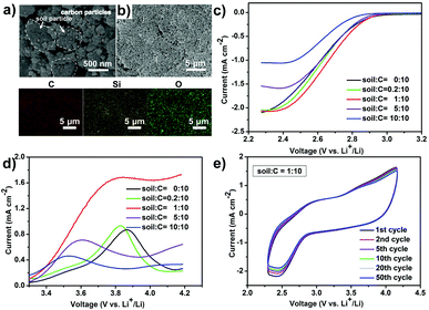
After calcination and ball milling, the treated soil presents a uniform granular morphology (0.5–5 μm of grain size) and is mixed with 100 nm-sized Vulcan XC-72 carbon (Fig. 1a and Fig. S1a, ESI†) by a physical grinding step. The soil is evenly distributed in Vulcan XC-72 carbon and a soil/C hybrid is obtained (Fig. 1b). In the element mapping, Si and O elements come from soil because the main content of soil is SiO2 (Fig. S1b, ESI†). The constructed soil/C hybrid is uniformly loaded on the glass carbon electrode as the catalyst for the following test. After mixing the treated soil and Vulcan XC-72 carbon (C) by different mass ratios, various soil/C hybrids were investigated by linear sweep voltammetry (LSV) methods on a RDE. For the oxygen reduction reaction (ORR, Fig. 1c) and oxygen evolution reaction (OER, Fig. 1d) tests of the hybrids, the limiting current density and the onset potential change as the mass ratios change. When the mass ratio of C to soil is 10![[thin space (1/6-em)]](https://www.rsc.org/images/entities/char_2009.gif) :
:![[thin space (1/6-em)]](https://www.rsc.org/images/entities/char_2009.gif) 1, the limiting current density is the largest (2.02 mA cm−2 in ORR, 1.70 mA cm−2 in OER) and the onset potential of ORR is the most positive (−0.42 V). Therefore, the optimized mass ratio of soil/C is fixed at 1
1, the limiting current density is the largest (2.02 mA cm−2 in ORR, 1.70 mA cm−2 in OER) and the onset potential of ORR is the most positive (−0.42 V). Therefore, the optimized mass ratio of soil/C is fixed at 1![[thin space (1/6-em)]](https://www.rsc.org/images/entities/char_2009.gif) :
:![[thin space (1/6-em)]](https://www.rsc.org/images/entities/char_2009.gif) 10 as the optimized result. The mass ratio of soil to C in the hybrid affects the electrocatalytic performance of ORR/OER via two factors, namely, electrical conductivity and the exposed active area of carbon. When carbon content in the soil/C hybrid is increased, the hybrid conductivity undoubtedly increases. This results in the decrease of ORR/OER overpotentials, showing a more positive onset potential of ORR. On the contrary, the decrease of carbon content in the hybrid would increase carbon dispersibility and make it expose more active areas, which benefits ORR/OER.
10 as the optimized result. The mass ratio of soil to C in the hybrid affects the electrocatalytic performance of ORR/OER via two factors, namely, electrical conductivity and the exposed active area of carbon. When carbon content in the soil/C hybrid is increased, the hybrid conductivity undoubtedly increases. This results in the decrease of ORR/OER overpotentials, showing a more positive onset potential of ORR. On the contrary, the decrease of carbon content in the hybrid would increase carbon dispersibility and make it expose more active areas, which benefits ORR/OER.
Cyclic voltammetry (CV) scanning runs 50 cycles (Fig. 1e), confirming the long-term catalytic durability of the hybrid towards ORR/OER. Such robust CV stability in an organic system has rarely been reported.11 The above catalytic activity and long term durability of the soil/C hybrid (1![[thin space (1/6-em)]](https://www.rsc.org/images/entities/char_2009.gif) :
:![[thin space (1/6-em)]](https://www.rsc.org/images/entities/char_2009.gif) 10, in mass) on RDE indicates a promising application in rechargeable Li–O2 batteries.
10, in mass) on RDE indicates a promising application in rechargeable Li–O2 batteries.
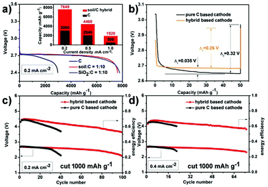
Fig. 2 presents the electrochemical performance of hybrid based cathodes in rechargeable Li–O2 batteries (the mass ratio of soil to C in the hybrid is 1![[thin space (1/6-em)]](https://www.rsc.org/images/entities/char_2009.gif) :
:![[thin space (1/6-em)]](https://www.rsc.org/images/entities/char_2009.gif) 10). The inset graph of Fig. 2a displays the rate capability comparison of the hybrid and the pure C based cathode by controlling the terminal voltage at 2.4 V. At a rate of 0.2 mA cm−2, the hybrid and the pure carbon-based cathode deliver an initial discharge capacity of 7640 mA h g−1 (3.82 mA h cm−2) and 3060 mA h g−1 (1.53 mA h cm−2), respectively. This initial discharge capacity of the soil/C hybrid is not inferior to precious metal-based catalysts (see Table S1 for literature comparison, ESI†). Although the increased current densities lead to capacity decrease, notably, the discharge capacity of the hybrid based cathode is always several times higher than the pure C cathode at each current density. In addition, the pure C based cathode shows a fast fading discharge voltage at 0.2 mA cm−2 in comparison with the relatively stable discharge plateau (2.71 V) of the hybrid cathode (Fig. 2a). This indicates the positive effect of VVE (soil) in the hybrid on capacity and discharge voltage. In order to make sure whether the impurities (aluminosilicates) within soil has ORR catalytic activity or not, we used quartz (pure SiO2) ball milled at 300 rpm for 20 h to fabricate a SiO2/C hybrid (the mass ratio of SiO2 to C is 1
10). The inset graph of Fig. 2a displays the rate capability comparison of the hybrid and the pure C based cathode by controlling the terminal voltage at 2.4 V. At a rate of 0.2 mA cm−2, the hybrid and the pure carbon-based cathode deliver an initial discharge capacity of 7640 mA h g−1 (3.82 mA h cm−2) and 3060 mA h g−1 (1.53 mA h cm−2), respectively. This initial discharge capacity of the soil/C hybrid is not inferior to precious metal-based catalysts (see Table S1 for literature comparison, ESI†). Although the increased current densities lead to capacity decrease, notably, the discharge capacity of the hybrid based cathode is always several times higher than the pure C cathode at each current density. In addition, the pure C based cathode shows a fast fading discharge voltage at 0.2 mA cm−2 in comparison with the relatively stable discharge plateau (2.71 V) of the hybrid cathode (Fig. 2a). This indicates the positive effect of VVE (soil) in the hybrid on capacity and discharge voltage. In order to make sure whether the impurities (aluminosilicates) within soil has ORR catalytic activity or not, we used quartz (pure SiO2) ball milled at 300 rpm for 20 h to fabricate a SiO2/C hybrid (the mass ratio of SiO2 to C is 1![[thin space (1/6-em)]](https://www.rsc.org/images/entities/char_2009.gif) :
:![[thin space (1/6-em)]](https://www.rsc.org/images/entities/char_2009.gif) 10). The cathode containing a SiO2/C hybrid exhibited an initial discharge capacity of 7780 mA h g−1 (3.89 mA h cm−2) and a middle voltage of 2.71 V (blue line in Fig. 2a), which are similar to the soil/C hybrid based cathode (7640 mA h g−1 & 2.71 V). This suggests that the impurities of soil do not have an extra catalytic activity. Moreover,the batteries in Ar only presented negligible capacity (Fig. S2, ESI†), indicating that the electrochemical performance of the presented batteries stems from the oxygen-involved reactions.
10). The cathode containing a SiO2/C hybrid exhibited an initial discharge capacity of 7780 mA h g−1 (3.89 mA h cm−2) and a middle voltage of 2.71 V (blue line in Fig. 2a), which are similar to the soil/C hybrid based cathode (7640 mA h g−1 & 2.71 V). This suggests that the impurities of soil do not have an extra catalytic activity. Moreover,the batteries in Ar only presented negligible capacity (Fig. S2, ESI†), indicating that the electrochemical performance of the presented batteries stems from the oxygen-involved reactions.
A simplified galvanostatic intermittent titration technique (GITT)12 is carried out at room temperature to further confirm the effect of VVE on discharge overpotential (Fig. 2b). The test program is a galvanostatic discharge at 500 mA g−1 for 6 min followed by 5 h rest. In the short duration (6 min), the hybrid based cathode has an extremely stable discharge plateau and always has a 0.035 V higher discharge voltage than that of the C cathode, whose discharge voltage falls slowly. During rest time (no current for 5 h), relaxation occurs. The voltages of both cathodes rise up, but there still are some differences. The relaxation degree (voltage gap) of the hybrid based cathode (0.26 V) is smaller than the pure C cathode (0.32 V). All the above data indicate that the hybrid based cathode has a smaller discharge overpotential and a shorter response time than the pure C based cathode.
The cycling ability of the hybrid based cathode is also tested. When cycled with a stopped capacity of 800 mA h g−1 (0.4 mA h cm−2), the terminal discharge voltage is above 2.1 V for 100 cycles at 0.2 mA cm−2 (Fig. 2c and Fig. S3a, ESI†). This cycling performance is one of the best reports for nonaqueous Li–O2 batteries with carbon based catalysts7,13 (see Table S2 for literature comparison, ESI†). The robust cyclability is also sustained for 73 cycles without obvious fading at a higher rate of 0.4 mA cm−2 (Fig. 2d and Fig. S3b, ESI†). The charge terminal voltages in Fig. 2c and d are directly depicted in Fig. S4 (ESI†). Regarding the composition, pure carbon cathodes only run 40 and 23 cycles at 0.2 and 0.4 mA cm−2, respectively (black lines in Fig. 2c and d). In addition, the hybrid cathode has higher energy efficiency (discharge voltage/charge voltage) in long term operation compared with that of pure C. All of the above comparisons show the much improved electrochemical performance that is a benefit from VVE (soil).
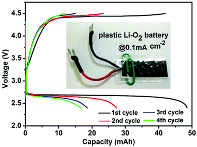
To demonstrate the practicability of the VVE assisted cathode, we assembled a “plastic Li–O2 battery14” (Fig. 3). Encouragingly, it could provide an initial capacity of 48.5 mA h (2425 mA h g−1 based on the loading mass on the cathode, or 10 mA h cm−2 based on the cathode area) with a middle discharge voltage of 2.68 V, corresponding to the energy density of 433 Wh kg−1 (48.5 × 2.68/0.3) and 395 Wh kg−1 (based on cell and consumed O2 mass). The energy density per unit area is ∼27 Wh cm−2. With further optimization of the cell design and structure, the energy density should be increased.
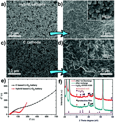
In order to further reveal the discharge/charge mechanism, both kinds of (soil/C hybrid and pure C) cathodes were dismantled from Li–O2 batteries and observed at two states (Fig. S5, ESI†): prior to discharge (state 1); after discharge to 2000 mA h g−1 (state 2). Compared with state 1 (Fig. 4a), the hybrid based cathode was evenly coated by discharged product and still had abundant voids at state 2 (Fig. 4b). On the contrary, the original porosity of the pure C cathode was blocked by aggregated discharge product at state 2 in comparison with state 1 (Fig. 4c and d). This phenomenon suggests that the hybrid based cathode has a larger exposed deposition space (or higher accommodation ability) for the discharge product.
The negative effect of the discharge product on the cathodes is demonstrated by the electrochemical impedance spectroscopy (EIS), as displayed in Fig. 4e. The curves show a much larger charge-transfer resistance (Rct, ∼500 Ω) on the pure C based cathode but quite a smaller impedance (Rct, ∼200 Ω) on the hybrid based cathode at state 2. The difference of the two impedances results from the change of the distribution of the discharge product as confirmed by the above SEM observation. The cathodes were also identified by XRD (Fig. 4f) and Raman (Fig. S6, ESI†). These techniques show the appearance/disappearance of Li2O2 peaks during discharging/recharging, illustrating the reversible formation/decomposition of Li2O2 (discharge product) on cathodes, which is crucial for the Li–O2 battery performance.15
The above results reveal the superior electrochemical performance of the soil/C hybrid to pure C. This improvement could be attributed to four factors. First, the addition of soil particles expands the exposed area of the C cathode for depositing more discharge product Li2O2, leading to the increase of the discharge capacity. Second, mass transfer channels of hybrid based cathodes could keep open for a longer time during discharge, guaranteeing O2/Li+ free-transport and high reaction kinetics. Third, the existence of VVE makes full use of shallow and deeper C particles, slowing down the passivation process of catalytic sites on the carbon surface. Fourth, evenly distributed Li2O2 in the hybrid based cathode has relatively low impedance and corresponding small overpotential, resulting in low polarization and high discharge voltage.
Conclusions
Soil as a void volume expander was mixed with commercial Vulcan XC-72 carbon to construct a soil/C hybrid catalyst for Li–O2 batteries. Owing to a larger exposed deposition area for the discharge product and full utilization of catalytic sites on the outer and inner carbon particles of the cathode, the soil/C hybrid cathodes exhibited a superior electrochemical performance. We obtained a large discharge capacity of 7640 mA h g−1, a good cyclability of 100 cycles and robust rate capability. This performance is comparable to noble metal containing catalysts. Furthermore, we tested plastic Li–O2 batteries, which present a high energy density of 395 Wh kg−1. Therefore, the soil/C hybrid catalyst with low cost and easy preparation should open a new direction for high-performance cathodes of rechargeable Li–O2 batteries.Acknowledgements
This work was supported by the National Programs of 973 (2011CB935900), NSFC (21231005 and 21322101), and MOE (B12015 and IRT13R30).References
- (a) M. Armand and J. M. Tarascon, Nature, 2008, 451, 652–657 CrossRef CAS PubMed; (b) F. Y. Cheng, J. Shen, B. Peng, Y. D. Pan, Z. L. Tao and J. Chen, Nat. Chem., 2011, 3, 79–84 CrossRef CAS PubMed; (c) F. Y. Cheng and J. Chen, Chem. Soc. Rev., 2012, 41, 2172–2192 RSC; (d) F. Y. Cheng and J. Chen, Acta Chim. Sin., 2013, 71, 473–477 CrossRef CAS.
- (a) F. Y. Cheng and J. Chen, Nat. Chem., 2012, 4, 962–963 CrossRef CAS PubMed; (b) C. Li, X. P. Han, F. Y. Cheng, Y. X. Hu, C. C. Chen and J. Chen, Nat. Commun., 2015, 6, 7345–7353 CrossRef CAS PubMed; (c) K. Zhang, X. P. Han, Z. Hu, X. L. Zhang, Z. L. Tao and J. Chen, Chem. Soc. Rev., 2015, 44, 699–728 RSC.
- J. L. Shui, F. Du, C. M. Xue, Q. Li and L. M. Dai, ACS Nano, 2014, 8, 3015–3022 CrossRef CAS PubMed.
- J. B. Park, J. Lee, C. S. Yoon and Y. K. Sun, ACS Appl. Mater. Interfaces, 2013, 5, 13426–13431 CAS.
- G. Wu, N. H. Mack, W. Gao, S. G. Ma, R. Q. Zhong, J. T. Han, J. K. Baldwin and P. Zelenay, ACS Nano, 2012, 6, 9764–9776 CrossRef CAS PubMed.
- Z. Y. Guo, D. D. Zhou, X. L. Dong, Z. J. Qiu, Y. G. Wang and Y. Y. Xia, Adv. Mater., 2013, 25, 5668–5672 CrossRef CAS PubMed.
- Q. Li, P. Xu, W. Gao, S. G. Ma, G. Q. Zhang, R. G. Cao, J. Cho, H. L. Wang and G. Wu, Adv. Mater., 2014, 26, 1378–1386 CrossRef CAS PubMed.
- (a) K. M. Abraham and Z. Jiang, J. Electrochem. Soc., 1996, 143, 1–5 CrossRef CAS PubMed; (b) T. Ogasawara, A. Débart, M. Holzapfel, P. Novák and P. G. Bruce, J. Am. Chem. Soc., 2006, 128, 1390–1393 CrossRef CAS PubMed; (c) F. J. Li, R. Ohnishi, Y. Yamada, J. Kubota, K. Domen, A. Yamada and H. S. Zhou, Chem. Commun., 2013, 49, 1175–1177 RSC.
- (a) C. Xia, M. Waletzko, K. Peppler and J. Janek, J. Phys. Chem. C, 2013, 117, 19897–19904 CrossRef CAS; (b) X. F. Hu, F. Y. Cheng, X. P. Han, T. R. Zhang and J. Chen, Small, 2014, 11, 809–813 CrossRef PubMed.
- (a) Y. L. Zhao, L. Xu, L. Q. Mai, C. H. Han, Q. Y. An, X. Xu, X. Liu and Q. J. Zhang, Proc. Natl. Acad. Sci. U. S. A., 2012, 109, 19569–19574 CrossRef CAS PubMed; (b) D. Sun, Y. Shen, W. Zhang, L. Yu, Z. Q. Yi, W. Yin, D. Wang, Y. H. Huang, J. Wang, D. L. Wang and J. B. Goodenough, J. Am. Chem. Soc., 2014, 136, 8941–8946 CrossRef CAS PubMed.
- (a) N. B. Aetukuri, B. D. McCloskey, J. M. García, L. E. Krupp, V. Viswanathan and A. C. Luntz, Nat. Chem., 2015, 7, 50–56 CrossRef CAS PubMed; (b) A. Kraytsberg and Y. Ein-Eli, Nano Energy, 2013, 2, 468–480 CrossRef CAS PubMed; (c) X. F. Hu, X. P. Han, Y. X. Hu, F. Y. Cheng and J. Chen, Nanoscale, 2014, 6, 3522–3525 RSC.
- K. M. Shaju, G. V. S. Rao and B. V. R. Chowdari, Electrochim. Acta, 2003, 48, 2691–2703 CrossRef CAS.
- (a) J. J. Xu, Z. L. Wang, D. Xu, L. L. Zhang and X. B. Zhang, Nat. Commun., 2013, 4, 2438–2448 Search PubMed; (b) Q. Li, P. Xu, W. Gao, S. G. Ma, G. Q. Zhang, R. G. Cao, J. Cho, H. L. Wang and G. Wu, Adv. Mater., 2014, 26, 1378–1386 CrossRef CAS PubMed.
- X. F. Hu, Z. Q. Zhu, F. Y. Cheng, Z. L. Tao and J. Chen, Nanoscale, 2015, 7, 11833–11840 RSC.
- (a) X. F. Hu, F. Y. Cheng, N. Zhang, X. P. Han and J. Chen, Small, 2015 DOI:10.1002/smll.201501570; (b) R. Choi, J. Jung, G. Kim, K. Song, Y. I. Kim, S. C. Jung, Y. K. Han, H. Song and Y. M. Kang, Energy Environ. Sci., 2014, 7, 1362–1368 RSC; (c) Y. X. Hu, T. R. Zhang, F. Y. Cheng, Q. Zhao, X. P. Han and J. Chen, Angew. Chem., Int. Ed., 2015, 54, 4338–4343 CrossRef CAS PubMed.
Footnote |
| † Electronic supplementary information (ESI) available: XRD, SEM, and additional electrochemical characterization. See DOI: 10.1039/c5qi00149h |
| This journal is © the Partner Organisations 2015 |

