Hierarchical nanoarray materials for advanced nickel–zinc batteries†
Zhiyi
Lu‡
,
Xiaochao
Wu‡
,
Xiaodong
Lei
,
Yaping
Li
and
Xiaoming
Sun
*
State Key Laboratory of Chemical Resource Engineering, Beijing University of Chemical Technology, Beijing 100029, China. E-mail: sunxm@mail.buct.edu.cn; Fax: +86-10-64425385; Tel: +86-10-64448751
First published on 24th December 2014
Abstract
In this work we report hierarchical Co3O4@NiO nanostrip@nanorod arrays (Co3O4@NiO NSRAs) which are directly grown on three-dimensional conductive substrates by a facile three-step hydrothermal reaction and a following annealing treatment. This hierarchical structure provides several advantages including a large contact surface area, a short ion diffusion path and good charge transport, which validate this film as an advanced electrode for nickel–zinc batteries with both high energy density (5.1 mW h cm−2) and power density (82.2 mW cm−2).
The need for the development of efficient energy storage devices with high safety for electrical vehicles as well as portable electronics is becoming more and more urgent.1–4 Lithium ion batteries (LIBs) have attracted the widest attention due to their high energy density; however, the flammability of organic electrolytes and the high reactivity of Li containing electrode materials will inevitably induce unsafe factors, which limit the widespread usage of LIBs.5,6 Aqueous rechargeable batteries (such as Ni–Zn battery,7,8 Ni–MH battery,9,10 and Ni–Fe battery11,12), which usually show much higher power density and safety, have attracted renewed interest as a possible alternative solution. Aqueous Ni–Zn batteries, where both Zn2+/Zn and Ni2+/Ni3+ conversion processes occur associated with water molecules, are thought to be an advanced energy storage system due to their relatively higher theoretical specific energy density (∼372 Wh kg−1), high open-circuit voltage, low toxicity and cost.7,13
For the NiZn battery system, the anode material is metallic Zn while the cathode material usually shows a much weaker conductivity (typically Ni(OH)2), which would significantly affect the electron transportation through the electrode with a high mass-loading, thus degrading the overall energy storage performance, including the specific capacity and rate capability. In order to improve the performance, the structure and morphology of the active materials should be further explored and optimized.14–16
Herein we designed and fabricated hierarchical Co3O4@NiO nanostrip@nanorod arrays (Co3O4@NiO NSRAs) as positive electrodes for Ni–Zn batteries. The NiO nanorods were uniformly and vertically grown outside of the Co3O4 nanostrip arrays, leading to the formation of a hierarchical structure. As demonstrated previously,16–21 constructing a hierarchical nanoarray structure was considered as an effective approach to achieve high utilization of the electrode material, because it not only facilitated the electron transport and electrolyte penetration, but also showed a synergistic effect of each component, thereby bringing about a boost improvement of the capacitive performance. This hierarchical architecture showed a high areal capacity (∼2.91 mA h cm−2), excellent rate capability (retains ∼61% of the capacity at 10 times higher current density), and prominent cycling stability (∼96% after 1000 cycles), which were benefited from the high mass-loading and high porosity of the active materials, and the direct contact with the current collector underlying. Besides, we paired the Co3O4@NiO NSRAs with a zinc anode in alkaline solution as a NiZn battery system, which delivered a peak energy density of ∼5.12 mW h cm−2 and a peak power density of ∼82.21 mW cm−2. The charge and discharge cycling stability of the battery showed a capacity degradation of ∼10% over 500 cycles at 50 mA cm−2 and the columbic efficiency of the battery was found to be greater than 97%, which were both receivable for an aqueous rechargeable battery system.
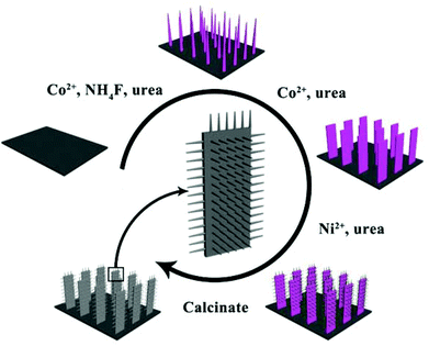
The fabrication process of Co3O4@NiO NSRAs is illustrated in Scheme 1. The nickel foam was chosen here as the substrate because of its zig-zag skeleton and high porosity, which helped to increase the active surface area.22 Co2(OH)2CO3 nanowires were firstly grown on the nickel foam to form a well-aligned array-like structure.23,24 Afterwards, the Co2(OH)2CO3 nanowires were converted into Co(OH)2 nanostrips by a secondary hydrothermal treatment, which dissolved and recrystallized the precursor nanowires.25 Thirdly, the Ni2+ salt was subsequently added and precipitated to obtain a hierarchical structure. It is notable that the film was bonded tightly to the foam substrate, as even hours of ultrasonication did not dislodge the colored material from the foam. Finally, the precursor hierarchical nanostrip@nanorod arrays were annealed to convert into the corresponding oxide materials.
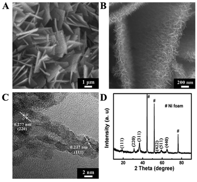
The surface morphology of the hierarchical structure was firstly investigated by scanning emission microscopy (SEM). The surface morphologies of the samples after the 1st and 2nd growth step are shown in Fig. S1,† revealing nanowire arrays (NWAs) and nanostrip arrays (NSAs) were successfully fabricated on the substrate. After Ni(II) salt precipitation and thermal treatment, hierarchical structures with multidirectional nanorods could be seen on the nanostrips, thus forming a highly dense film (Fig. 1A and B). The resulting NSRAs were vertically aligned on the substrate and the total size of the assembled structure was in the range of 2–4 μm while its thickness was about 400 nm. The average diameter and length of the nanorods were estimated to be about 10–15 nm and 100–200 nm, respectively.
 | ||
| Fig. 1 (A) and (B) SEM images of the hierarchical Co3O4@NiO NSRAs with different magnifications; (C) and (D) HRTEM image and XRD pattern of the hierarchical Co3O4@NiO NSRAs. | ||
A high resolution TEM image (Fig. 1C) was further measured to gain more structural information. Two lattice spacings (0.237 nm and 0.277 nm), corresponding to the (111) plane of NiO and the (220) plane of NiCo2O4 were observed in an individual nanorod, indicating that the tip was composed of NiO and the root was mainly made of spinel-type mixed metal oxides.17 Only the spinel phase was found in the XRD pattern (Fig. 1D), suggesting that the NiO nanorods were poorly crystallized with small crystal grains, which was consistent with the HRTEM results. X-ray photoelectron spectroscopy (XPS, Fig. S2†) demonstrated the +2 oxidation state of Ni and the mixed oxidation state (2+ and 3+) of Co with a Ni/Co ratio of 4, while the energy dispersive spectroscopy (EDS, Fig. S3†) result showed a much smaller Ni/Co ratio of 2.5![[thin space (1/6-em)]](https://www.rsc.org/images/entities/char_2009.gif) :
:![[thin space (1/6-em)]](https://www.rsc.org/images/entities/char_2009.gif) 1, thus confirming the vast majority of the materials in the surface of the hierarchical structure (i.e. the tip of the secondary nanorod) was NiO.
1, thus confirming the vast majority of the materials in the surface of the hierarchical structure (i.e. the tip of the secondary nanorod) was NiO.
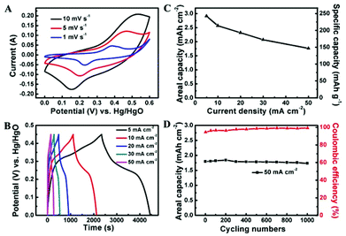
The electrochemical properties of Co3O4@NiO NSRAs were examined by cyclic voltammetry (CV) and charge/discharge measurements using a standard three electrode system in 6 M KOH. The representative CV curves at scan rates of 1, 5 and 10 mV s−1 are shown in Fig. 2A, where a pair of obvious redox peaks was observed. It was attributed to the redox couples of Ni2+/Ni3+ and Co2+/Co3+ (ref. 17 and 26), which were located at similar equilibrium potentials (ΔE < 0.1 V), thus leading to the formation of overlapped and broad peaks. As the sweep rate was increased, the anodic peak potential and cathodic peak potential shifted to more anodic and cathodic directions, respectively, and this phenomenon might be caused by the polarization effect including concentration polarization and resistance effect. The typical charge and discharge profiles of the NSRAs at different current densities are presented in Fig. 2B. It can be observed that the voltage plateaus were located between 0.2 V and 0.3 V in the discharge curves, consistent with the position of the anodic peak in CV curves. The symmetric shape of the charge and discharge process illustrated the high columbic efficiency of the electrode material (at least 95% for various current densities). Calculated from the discharge curves (Fig. 2C), the areal capacity delivered as high as 2.91 mA h cm−2 (corresponding to a specific capacity of ∼242.4 mA h g−1) at a current density of 5 mA cm−2, while the capacity could be retained at 1.76 mA h cm−2 as the current density increased to 50 mA cm−2, showing a rate capability of ∼60.5%. The remarkable rate capability as well as the ultrahigh areal capacity manifested the effectiveness of constructing ordered hierarchical mesoporous architecture. For comparison purposes, the Co3O4 NWAs and NSAs after the 1st and the 2nd growth step and the annealing process were evaluated using similar measurements (Fig. S4†). It was found that both Co3O4 NWAs and NSAs showed much inferior performance, which indicated that the addition of NiO and the hierarchical construction were both beneficial for achieving high areal and specific capacity.
Long-term cycling stability is another essential factor for practical application. Over 1000 cycles of charge/discharge testing were employed to examine the service life of the Co3O4@NiO NSRA electrode at a current density of 50 mA cm−2 (Fig. 2D). The specific capacity decreased slightly (∼4%) over the initial 100 cycles and subsequently remained essentially unchanged over the following 900 cycles. Moreover, the coulombic efficiency of the electrode gradually increased and maintained at ∼98% upon cycling testing. The high stability indicated that the charge/discharge processes did not induce structural change of the electrodes which would influence the surface redox reactions. A combination of the above features (high areal capacity, remarkable rate capability and excellent stability) was attributed to the hierarchical structure design with the integration of unique merits of Co3O4 nanostrips as scaffolds to render a fast electron transport and superior electrolyte diffusion and ultrathin NiO nanorods with a high electrochemically active surface area, thus leading to substantially improved capacitive and rate performance.
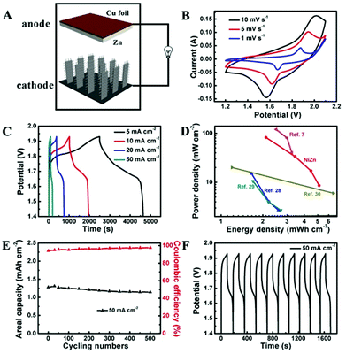
The potential application of Co3O4@NiO NSRAs in aqueous NiZn batteries was further investigated by incorporation of zinc as the anode (Fig. 3A). An aqueous solution of 6 M KOH saturated with ZnO was used as the electrolyte. Copper foil was used as both the current collector and the substrate for electrodeposition of Zn. The CV curves of the NiZn battery at various scan rates are shown in Fig. 3B, where a pair of redox peaks was observed. These peaks corresponded to the following reactions.8,27
Anodic reaction:
| Zn(OH)42− + 2e− ↔ Zn + 4OH− | (1) |
Cathodic reaction:
| NiO + OH− − e− ↔ NiOOH | (2) |
| Co3O4 + H2O + OH− − e− ↔ 3CoOOH | (3) |
To quantitatively measure the energy storage performance of the NiZn battery, galvanostatic charge/discharge curves at different current densities were obtained (Fig. 3C). The calculated specific capacity of the aqueous NiZn battery was ∼2.89 mA h cm−2 (or 182.6 mA h g−1) at a current density of 5 mA cm−2, and it was still maintained at as high as ∼1.28 mA h cm−2 (or 80.5 mA h g−1) when the current density was increased to 50 mA cm−2. Together with the high operating voltage (∼1.7 V), this NiZn battery showed comparable or higher energy density and power density compared with other batteries reported,7,28–30 as shown in the Ragone plot in Fig. 3D. This NiZn battery could deliver an areal energy density of 5.12 mW h cm−2 at a power density of 8.61 mW cm−2, and an energy density of 2.11 mW h cm−2 at a power density of 82.21 mW cm−2. Although the high areal energy density was partially by virtue of the high mass-loading, the calculated specific energy density and the power density (215.51 Wh kg−1 and 3.45 kW kg−1) were still comparable or higher than the previous data.7,13,31,32 To demonstrate the practical application of the battery, we engineered a pouch cell of our samples, which was used to light a commercial light-emitting diode (LED) (Fig. S5†). The tandem aqueous batteries (two devices connected in series) could easily light up a LED for hours after being fully charged.
The long-term stability was also examined by cycling testing, as shown in Fig. 3E and F. Unlike the highly stable Co3O4@NiO NSRA electrodes, the NiZn battery showed a quasi-stable performance with a capacity degradation of ∼11% after 500 cycles. This was attributed to the Zn dendrite formation on the Cu substrate,33,34 which might result in decreasing the effective working area and decelerating the Zn deposition process. The SEM images of the Zn electrode after first 5 cycles and 500 cycling tests are shown in Fig. S6.† Notably, the coulombic efficiency of the battery could achieve above 97% during the cycling testing at a high rate, illustrating the good reversibility.
In summary, we have developed a multi-step hydrothermal reaction and a following calcination process to fabricate hierarchical Co3O4@NiO NSRAs directly grown on a conductive substrate. Due to the unique architecture, the hierarchical nanoarrays exhibited an outstanding capacitive performance as the positive electrodes. Moreover, by incorporating a zinc anode, an aqueous NiZn battery was fabricated, which delivered both high energy density and power density. This study not only provides a battery technology with the advantages of high energy and power density, cost-effectiveness and high safety, but also clearly demonstrates the feasibility of constructing hierarchical nanoarrays on a variety of energy storage applications.
This work was supported by the National Natural Science Foundation of China, the 973 Program (2011CBA00503 and 2011CB932403), the Program for New Century Excellent Talents in Universities, and the Program for Changjiang Scholars and Innovative Research Team in University.
Notes and references
- C. Liu, F. Li, L. P. Ma and H. M. Cheng, Adv. Mater., 2010, 22, E28–E62 CrossRef CAS PubMed.
- J. Jiang, Y. Li, J. Liu, X. Huang, C. Yuan and X. W. Lou, Adv. Mater., 2012, 24, 5166–5180 CrossRef CAS PubMed.
- A. L. Mohana Reddy, S. R. Gowda, M. M. Shaijumon and P. M. Ajayan, Adv. Mater., 2012, 24, 5045–5064 CrossRef PubMed.
- H. Wang and H. Dai, Chem. Soc. Rev., 2013, 42, 3088–3113 RSC.
- P. Poizot, S. Laruelle, S. Grugeon, L. Dupont and J.-M. Tarascon, Nature, 2000, 407, 496–499 CrossRef CAS PubMed.
- X. Zhou, L. J. Wan and Y. G. Guo, Adv. Mater., 2013, 25, 2152–2157 CrossRef CAS PubMed.
- M. Gong, Y. Li, H. Zhang, B. Zhang, W. Zhou, J. Feng, H. Wang, Y. Liang, Z. Fan, J. Liu and H. Dai, Energy Environ. Sci., 2014, 7, 2025–2032 CAS.
- X. Fan, Z. Yang, R. Wen, B. Yang and W. Long, J. Power Sources, 2013, 224, 80–85 CrossRef CAS PubMed.
- B. Li, H. Cao, J. Shao, H. Zheng, Y. Lu, J. Yin and M. Qu, Chem. Commun., 2011, 47, 3159–3161 RSC.
- Y. Liu, H. Pan, M. Gao and Q. Wang, J. Mater. Chem., 2011, 21, 4743 RSC.
- H. Wang, Y. Liang, M. Gong, Y. Li, W. Chang, T. Mefford, J. Zhou, J. Wang, T. Regier, F. Wei and H. Dai, Nat. Commun., 2012, 3, 917 CrossRef PubMed.
- C. Long, T. Wei, J. Yan, L. Jiang and Z. Fan, ACS Nano, 2013, 7, 11325–11332 CrossRef CAS PubMed.
- M. Ma, J. P. Tu, Y. F. Yuan, X. L. Wang, K. F. Li, F. Mao and Z. Y. Zeng, J. Power Sources, 2008, 179, 395–400 CrossRef CAS PubMed.
- R. K. Joshi and J. J. Schneider, Chem. Soc. Rev., 2012, 41, 5285–5312 RSC.
- Z.-S. Wu, G. Zhou, L.-C. Yin, W. Ren, F. Li and H.-M. Cheng, Nano Energy, 2012, 1, 107–131 CrossRef CAS PubMed.
- C. K. Chan, H. Peng, G. Liu, K. McIlwrath, X. F. Zhang, R. A. Huggins and Y. Cui, Nat. Nanotechnol., 2008, 3, 31–35 CrossRef CAS PubMed.
- Z. Lu, Q. Yang, W. Zhu, Z. Chang, J. Liu, X. Sun, D. G. Evans and X. Duan, Nano Res., 2012, 5, 369–378 CrossRef CAS PubMed.
- Q. Yang, Z. Lu, T. Li, X. Sun and J. Liu, Nano Energy, 2014, 7, 170–178 CrossRef CAS PubMed.
- H. Chen, L. Hu, M. Chen, Y. Yan and L. Wu, Adv. Funct. Mater., 2014, 24, 934–942 CrossRef CAS.
- L. Hu, W. Chen, X. Xie, N. Liu, Y. Yang, Hui Wu, Y. Yao, M. Pasta, H. N. Alshareef and Y. Cui, ACS Nano, 2011, 5, 8904–8913 CrossRef CAS PubMed.
- W. Chen, R. B. Rakhi, L. Hu, X. Xie, Y. Cui and H. N. Alshareef, Nano Lett., 2011, 11, 5165–5172 CrossRef CAS PubMed.
- J. Wang, H. X. Zhong, Y. L. Qin and X. B. Zhang, Angew. Chem., Int. Ed., 2013, 52, 5248–5253 CrossRef CAS PubMed.
- Q. Yang, Z. Lu, Z. Chang, W. Zhu, J. Sun, J. Liu, X. Sun and X. Duan, RSC Adv., 2012, 2, 1663 RSC.
- W. Zhu, Z. Lu, G. Zhang, X. Lei, Z. Chang, J. Liu and X. Sun, J. Mater. Chem. A, 2013, 1, 8327 CAS.
- Q. Yang, Z. Lu, X. Sun and J. Liu, Sci. Rep., 2013, 3, 3537 Search PubMed.
- F. Zhang, C. Yuan, J. Zhu, J. Wang, X. Zhang and X. Lou, Adv. Funct. Mater., 2013, 23, 3909–3915 CrossRef CAS.
- B. Yang, Z. Yang and R. Wang, J. Power Sources, 2014, 251, 14–19 CrossRef CAS PubMed.
- K. Sun, T. S. Wei, B. Y. Ahn, J. Y. Seo, S. J. Dillon and J. A. Lewis, Adv. Mater., 2013, 25, 4539–4543 CrossRef CAS PubMed.
- K. Yoshima, H. Munakata and K. Kanamura, J. Power Sources, 2012, 208, 404–408 CrossRef CAS PubMed.
- A. M. Gaikwad, G. L. Whiting, D. A. Steingart and A. C. Arias, Adv. Mater., 2011, 23, 3251–3255 CrossRef CAS PubMed.
- J. Jindra, J. Power Sources, 2000, 88, 202–205 CrossRef CAS.
- X. Wu, Z. Lu, W. Zhu, Q. Yang, G. Zhang, J. Liu and X. Sun, Nano Energy, 2014, 10, 229–234 CrossRef CAS PubMed.
- Y. Li and H. Dai, Chem. Soc. Rev., 2014, 43, 5257–5275 RSC.
- Y. Li, M. Gong, Y. Liang, J. Feng, J. E. Kim, H. Wang, G. Hong, B. Zhang and H. Dai, Nat. Commun., 2013, 4, 1805 CrossRef PubMed.
Footnotes |
| † Electronic supplementary information (ESI) available: Experimental section, XPS survey, SEM, EDS and XRD results, and electrochemical testing results. See DOI: 10.1039/c4qi00143e |
| ‡ These authors contributed equally to this work. |
| This journal is © the Partner Organisations 2015 |


