
Porous ZnCo2O4 nanoparticles derived from a new mixed-metal organic framework for supercapacitors†
Siru
Chen
,
Ming
Xue
*,
Yanqiang
Li
,
Ying
Pan
,
Liangkui
Zhu
,
Daliang
Zhang
,
Qianrong
Fang
and
Shilun
Qiu
*
State Key Laboratory of Inorganic Synthesis and Preparative Chemistry, Jilin University, Changchun 130012, P. R. China. E-mail: sqiu@jlu.edu.cn; xueming@jlu.edu.cn
First published on 26th December 2014
Abstract
Cobalt-based oxides have been shown to be promising materials for application in high-energy-density Li-ion batteries and supercapacitors. In this paper, we report a new and simple strategy for the synthesis of a mixed-metal spinel phase (ZnCo2O4) from a zinc and cobalt mixed-metal organic framework (JUC-155). It is important to rationally design a MOF with a precise ratio (Co/Zn) and a synthetic process that is simple and time saving. After solid-state annealing of the mixed-metal MOF precursor at 400 °C for two hours, a pure ZnCo2O4 phase with a high surface area (55 cm2 g−1) was obtained. When used as electrode materials for supercapacitors, an exceptionally high specific capacitance of 451 F g−1 was obtained at the scan rate of 5 mV s−1. The capacitance loss after 1500 cycles was only 2.1% at a current density of 2 A g−1, indicating that this phase has an excellent cycling stability. These remarkable electrochemical performances suggest that this phase is potentially promising for application as an efficient electrode in electrochemical capacitors.
Introduction
In recent years, electrochemical capacitors, also known as supercapacitors, have received a large amount of attention as an important power storage device due to their high power density, fast recharge capability and long cycle life.1–4 Generally, these electrochemical capacitors can be divided into two categories, electrical double layer capacitors (EDLC) and pseudocapacitors, based on their charge storage mechanisms.5,6 Usually, EDLC materials are high-surface-area, carbon-based materials (such as aerogel, nanofoam, and nanotubes) that store the energy by forming a double layer between the electrode and the electrolyte through electrostatic interaction.7,8 Pseudocapacitors rely on the surface redox process on the electrode to generate capacitance and the used materials from this process usually possess multiple oxidation states/structures capable of rich redox reactions, for example, conducting polymers and transition metal oxides, nitrides, and sulphides.9,10 Due to the fast redox reactions that take place on the electrode's surface, pseudocapacitors usually exhibit much higher specific capacitance than EDLCs.7,11 Of these products, RuO2 is the most notable due to its wide use and application in electrochemical supercapacitance studies. However, the sheer high cost and rareness of Ru have limited its industrial prominence, and it is important to investigate the possibility of making cheaper electrode materials with excellent electrochemical performances.12 For example, cobaltite-based materials, in particular Co3O4, have received a great deal of interest due to their superior application in supercapacitors. However, because there is only monometal cobalt in this compound and the redox reaction is not rich enough, it is still an urgent task to search for new materials with richer redox reactions.13,14Spinel zinc cobaltite (ZnCo2O4) is isomorphic to the Co3O4 crystal structure and seems to be a promising alternative owing to its higher conductivity and richer redox reactions, caused by the coupling of the two metal species.13,14 Various approaches have been used to synthesise ZnCo2O4 nanomaterials, for example, co-precipitation, the sol–gel method and synthesis on a particular support.15–20 The supercapacitive property of ZnCo2O4 was investigated in prior efforts that showed that ZnCo2O4 is an excellent electrode material for supercapacitors. For example, ZnCo2O4 synthesized by co-precipitation shows a specific capacitance of 77 F g−1 at 5 mV s−1 scan rate.17 Using an epoxide driven, sol–gel method, Davis et al. obtained zinc cobaltite nanocrystals with exceptional capacitance and excellent cycle durability.18 In addition, there are some literature reports about ZnCo2O4 grown on Ni foam, which also show good capacitance properties.19,20 Although there have been several successful attempts to synthesise ZnCo2O4 nanomaterials, it is difficult to control the structure and porosity of the obtained mixed-metal oxides. Thus it is important to develop a simple method for producing spinel structured metal oxides with a high surface area and well-defined composition and morphology.
Metal–organic framework (MOFs) materials have attracted considerable attention in recent years due to their high surface area and porosity. These materials have been investigated for use in gas storage and separation, catalysis, ion exchange, and chemical sensors.21–27 Recently, they have been also used as a template or precursor to obtain different nanomaterials, including porous carbon and metal oxides.28–32 For example, Xu et al. first used the direct thermolysis method to prepare porous carbon with MOF-5 as a carbon precursor.33 You et al. reported the large-scale fabrication of multi-walled carbon nanotubes (MCNTs) through one-step, direct thermolysis of a metal–organic framework [Ni3(btc)2·12H2O] (btc = benzene-1,3,5-tri-carboxylate) precursor under the protection of an inert gas.34 Cho et al. synthesised spindle-like mesoporous Fe2O3 for lithium batteries through the calcination of MIL-88-Fe.35 Fe2O3 microboxes with hierarchical shell structures were synthesised by Lou et al. from Prussian blue microcubes and these structures display a high specific capacity of 950 mA h−1 at 200 mA g−1 in lithium ion batteries.36 The synthesis of metal oxides from MOFs has obvious advantages compared to other methods owing to their high surface area and unique structure. The resulting metal oxides usually have a high surface area and high conductivity, properties that are highly desirable for supercapacitors. Although many metal oxides have been developed using this method, the most reported are single-metal oxides and the synthesis of mixed-metal oxides from mixed-metal MOFs has rarely been seen. To the best of our knowledge, there have not yet been reports of using MOFs to synthesise a mixed-metal oxide for supercapacitors.37–40 Usually, mixed-metal MOFs can be constructed by both pre- and post-synthetic methods. In the past decade, some mixed-metal MOFs have been reported, particularly as magnetic MOF materials.41 It is common to construct these MOFs by using various metal ions in the reaction. Recently, post-synthetic ion metathesis (PSIM) was also found to be a simple method to construct mixed-metal MOFs with special properties.42,43 It is worth noting that some important functional mixed-metal MOFs were constructed by metalloligands, which have a variety of different functional sites, such as open metal sites, catalytic active metal sites etc.44,45 Furthermore, mixed-metal oxides with richer redox reactions show higher capacitance.14 So, mixed-metal MOFs constructed with Ni, Co, Zn, and Mn metals will be good precursors for the synthesis of new mixed-metal oxide materials as supercapacitor electrodes.
Therefore, we designed and synthesised a new mixed-metal MOF ZnCo2O(BTC)2(DMF)·H2O with a three-dimensional structure, named JUC-155 (JUC = Jilin University China), using the traditional solvent thermal method. Using JUC-155 as the precursor, pure phase ZnCo2O4 nanoparticles were prepared via solid-state transformations at three different temperatures. The optimal sample with a high surface area was obtained at a low temperature and showed promise as a potential electrode material for supercapacitors. Electrochemical measurements demonstrated that the as-prepared ZnCo2O4 materials possessed a large specific capacitance and a high electrochemical stability.
Experimental
Synthesis of ZnCo2O(BTC)2(DMF)·H2O (JUC-155)
A mixture of ZnCl2 (0.0136 g, 0.1 mmol), CoCl2·6H2O (0.0476 g, 0.2 mmol), BTC (1,3,5-benzenetricarboxylic, 0.11 g, 0.5 mmol), DMF (N,N′-dimethylformamide, 10 mL) and H2O (2 mL) was placed in a 25 mL vial to form a solution under stirring. After stirring in air for 30 minutes, the vial was set in a beaker (100 mL) containing a DMF solution (5 mL) of triethylamine (0.10 mL) and then sealed and left undisturbed for six hours at 80 °C. After cooling down to room temperature, the purplish-red, block-shaped crystals of JUC-155 were collected, washed with DMF, and dried.Synthesis of ZnCo2O4 nanoparticles (compounds 1, 2 and 3)
To synthesise ZnCo2O4 particles, JUC-155 was introduced into a quartz crucible placed within a horizontal quartz tube furnace at a ramp rate of 2 °C min−1 to a final temperature of 400 °C for two hours in air. After thermolysis of the organic species, the sample was slowly cooled to room temperature. Finally, a metallic black ZnCo2O4 sample was obtained and named as compound 1. The yield was 32.7% with respect to the starting material, which is in accordance with the theoretical yield (34.2%) from C21H17NO16ZnCo2 to ZnCo2O4. Similarly, compounds 2 and 3 were obtained by heating the JUC-155 at 450 °C and 500 °C, respectively, for two hours with a heating rate of 2 °C min−1.Characterization
Diffraction intensities for JUC-155 were collected on a computer-controlled Bruker SMART CCD diffractometer equipped with graphite-monochromated Mo-Kα (λ = 0.71073 Å) radiation at room temperature using the ω-scan technique. The structure was solved by direct methods and refined with the full-matrix least-squares technique using the program SHELXTL.46 All non-hydrogen atoms in the structure of JUC-155 were refined anisotropically. Hydrogen atoms of organic ligands (BTC) and terminal molecules (DMF) were located geometrically.The powder X-ray diffraction (PXRD) data were collected on a SHIMADZU LabX XRD-6000 diffractometer with Cu-Kα radiation (λ = 1.5418 Å) at room temperature.
The Fourier transform infrared (FTIR) spectra (KBr, Aldrich) were measured using a Shimadzu IRAFFINITY-1 Fourier transform infrared spectrometer. Samples were packed firmly to obtain transparent films.
The thermogravimetric analysis (TGA) was performed using a SHIMADZU DTG-60 thermal analyser system at a heating rate of 10 °C min−1 to 600 °C in dried air with a flow rate of 30 mL min−1. The sample was loaded on an alumina pan.
Scanning electron microscopy (SEM) and energy dispersive spectrometer (EDS) analyses were performed on a JEOS JSM-6510.
A transmission electron microscope, JEM-2010, was used for the transmission electron microscopy studies. A Gatan 794 CCD camera was used for recording transmission electron microscopy images.
Nitrogen adsorption/desorption measurements were carried out at 77 K with an Autosorb iQ MP (Quantachrome Instruments) to determine the surface area. Before the sorption analysis, the sample was evacuated at 200 °C for 10 hours using a turbo molecular vacuum pump. Specific surface areas were calculated from nitrogen adsorption data by multipoint BET analysis.
Electrochemical measurements
The working electrodes were prepared by grinding ZnCo2O4 (80 wt%, about 40 mg), acetylene black (15 wt%, about 7.5 mg), polytetrafluoroethylene (5 wt% PTFE, 60 wt% in water, diluted to 6 wt% before use), and a few drops of ethanol to form a homogeneous slurry and made into a film of about 16 cm2. The film was dried at 80 °C for 24 hours under a vacuum and was cut into squares of about 1 cm2. It was then pressed onto nickel foam under 10 MPa pressure. The typical mass load of the electrode was about 3 mg cm−2. Cyclic voltammograms (CV) and galvanostatic charge–discharge curves were collected using a CHI660D electrochemical workstation (Chenhua, Shanghai, China). The electrochemical experiments were carried out using a three-electrode cell in 6.0 M KOH electrolyte, using platinum as the counter electrode and an Ag/AgCl electrode as the reference electrode.Results and discussion
Single crystal X-ray crystallography revealed that the mixed-metal MOF JUC-155 crystallises into a tetragonal system with a space group of I4cm (no. 108). The crystallographic data are summarised in Table 1 and selected bond lengths and bond angles of JUC-155 are listed in Table S1.† The fundamental building unit of JUC-155 contains one zinc ion, two cobalt ions, six crystallographically equivalent BTC ligands, one central bridging oxygen atom, and one terminal DMF molecule. As shown in Fig. 1a, the Zn1 centre adopts distorted octahedral coordination geometries with six oxygen atoms from four different BTC ligands, one coordinated DMF molecule, and one central bridging oxygen atom. The Co1 centre is coordinated by four oxygen atoms to form a slightly distorted tetrahedron. Clearly, the trinuclear metal cluster ZnCo2 is held together by a central bridging oxygen atom and four independent carboxyl groups. Then the trinuclear cluster links to each other through the BTC ligands to construct a 3D, porous framework. The framework contains approximately 6.3 × 6.3 Å2 and 10.7 × 10.7 Å2 1D channels viewed along the c axis (Fig. 1a).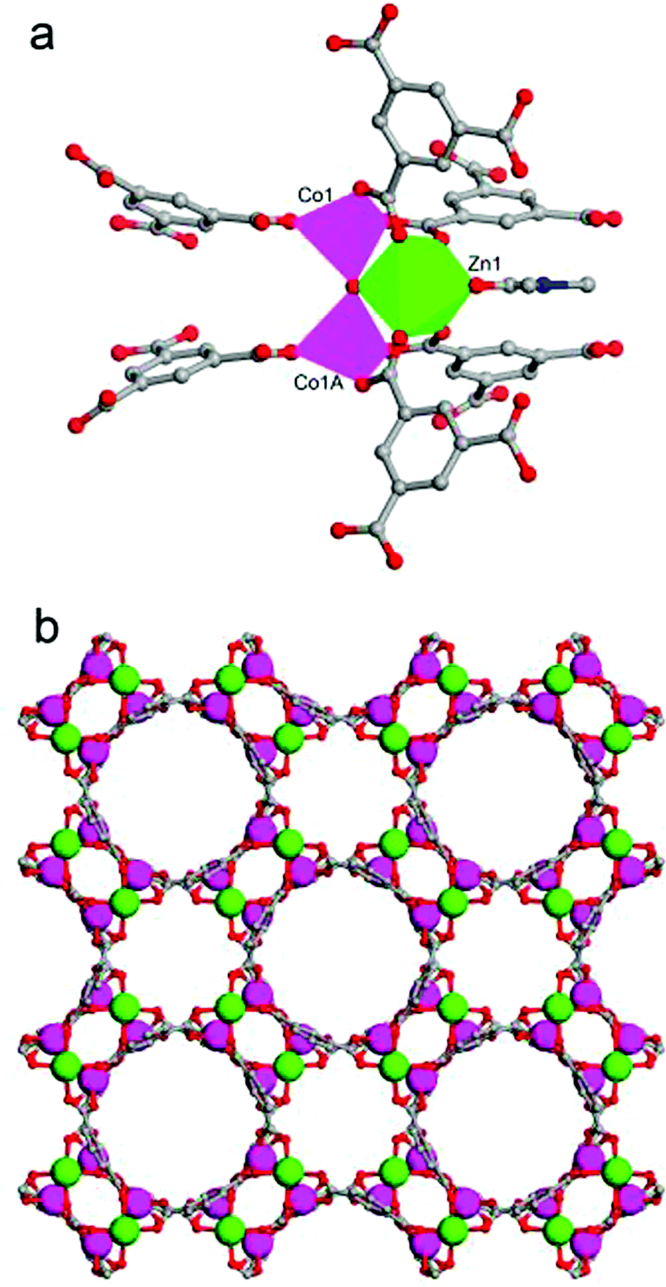 | ||
| Fig. 1 (a) Fundamental building unit of JUC-155 and (b) 3D structure of JUC-155 with 1D channels viewed along the [001] direction; Zn green, Co pink, C gray, N blue, and O red; H atoms are omitted for clarity. | ||
| Parameter | ZnCo2O(BTC)2(DMF)(H2O)·H2O (JUC-155) |
|---|---|
| a R = ∑||Fo| − |Fc||/∑|Fo|. b R w = [∑w(Fo2 − Fc2)2/∑w(Fo2)2]1/2. | |
| Empirical formula | C21H7N1Zn1Co2O15 |
| Formula weight | 696.51 |
| Crystal system | Tetragonal |
| Space group | I4cm |
| a [Å] | 20.796(3) |
| b [Å] | 20.796(3) |
| c [Å] | 17.869(4) |
| α [°] | 90 |
| β [°] | 90 |
| γ [°] | 90 |
| V [Å3] | 7728(2) |
| Z | 8 |
| T (K) | 293 |
| λ (Å) | 0.71073 |
| ρ calcd (Mg m−3) | 1.197 |
| μ (mm−1) | 1.515 |
| GOF on F2 | 1.009 |
| R [I > 2σ(I)] | 0.0787 |
| R w | 0.1679 |
The formation of JUC-155 was confirmed by the PXRD results shown in Fig. 2a. The pattern is in agreement with the simulated one, confirming the structure of JUC-155, that is, isostructural with MOF-38 (Zn-btc).47 It should be noted that the relative intensities of the as-synthesized PXRD are slight different compared with the simulation because of the orientation of JUC-155 crystals. As shown in SEM images, the JUC-155 shows quadrangular rod morphology with a length of about 20 μm and a width of about 6 μm (Fig. S1a†). The energy dispersive spectroscopy (EDS) analysis shows that JUC-155 is composed of cobalt and zinc elements and that the molar ratio is about two (Fig. S2†). The elemental distribution analysis of the selected region further confirms that the zinc and cobalt elements are homogeneously distributed in the whole samples, as shown in Fig. S1b.†
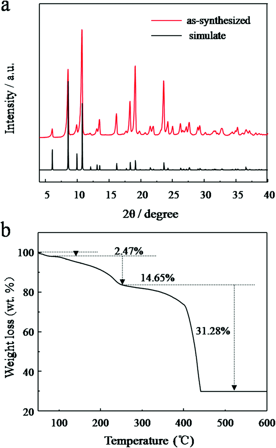 | ||
| Fig. 2 (a) PXRD patterns of the simulated single crystal crystallography data and as-synthesized JUC-155; (b) TG analysis curve of the as-synthesized JUC-155 crystal under air flow. | ||
A Fourier transform infrared (FTIR) spectrum was used to study the composition of JUC-155. As shown in Fig. S3,† after the coordination of carboxyl to Co and Zn there are two strong bands at 1574 cm−1 and 1373 cm−1 assigned to the asymmetric and symmetric stretching modes of the coordinated (COO−) group. The broad and strong band centred at 3425 cm−1 produced from H2O of hydration appears, suggesting the existence of coordinated and free solvent H2O molecules in the MOF. The characterisation peak of a protonated carboxylate group at 1730–1680 cm−1 does not appear, indicating that the BTC ligands are completely deprotonated.
The thermal stability of the as-synthesised JUC-155 was investigated by the TG analysis technique. Fig. 2b shows the TGA curves recorded from 50 °C to 600 °C. Three obvious weight-loss steps were observed. The first occurred in the range of 50 to 104 °C corresponding to a 2.47% weight loss, which is related to the elimination of one water guest molecule (calculated at 2.49%). The second weight loss (of 13.45%) occurs between 110 °C and 260 °C, owing to the loss of one coordinated water molecule and one coordinated DMF molecule (calculated at 12.60%). The final step starting at 350 °C indicates the decomposition of BTC species in the MOF at the same time as the framework begins to collapse.
Based on the TGA result, the JUC-155 was calcinated at three different temperatures (400, 450, and 500 °C) for two hours to obtain ZnCo2O4 materials 1, 2 and 3, respectively. As shown in Fig. 3, all of the diffraction peaks in the sample can be readily assigned to the spinel ZnCo2O4 phase (JCPDS card no. 23-1390). No characterisation peaks from other impurities were observed, indicating the high purity of the decomposed product. The morphologies of the three compounds were investigated by SEM and TEM. Compared to the morphology of JUC-155, the ZnCo2O4 materials showed a coarse shape and their size decreased a little because of the decomposition of the organic species (Fig. S4a–c†). The uniform distribution of Zn and Co species was confirmed by elemental mapping (Fig. S4d–f†). The molar ratio of Co and Zn elements is about two, as confirmed by EDS analysis (Fig. S5†). TEM was performed to learn the exact particle size and the shape of the ZnCo2O4 samples. As can be seen in Fig. 4, the TEM results indicated that the bulk ZnCo2O4 is composed of numerous ZnCo2O4 nanoparticles with size less than 20 nm and these nanoparticles can further aggregate to form a porous structure. Furthermore, the lattice fringes from HRTEM can be readily indexed to the 111 and 400 crystal planes of the ZnCo2O4 phase. The selected area electron diffraction (SAED) pattern shown as the inset can also be indexed to the spinel ZnCo2O4 phase, which is in agreement with the PXRD results.
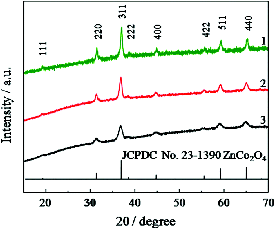 | ||
| Fig. 3 PXRD patterns of compounds 1, 2, and 3 and the standard patterns of ZnCo2O4. | ||
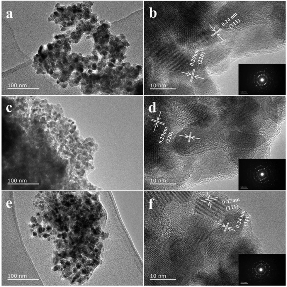 | ||
| Fig. 4 TEM images of porous ZnCo2O4 particles: (a, b) 1, (c, d) 2, and (e, f) 3. Insets (in b, d and f) are corresponding SAED patterns. | ||
A nitrogen adsorption–desorption analysis was performed at 77 K to investigate the porous features of ZnCo2O4 (Fig. S6†). From the adsorption studies, it is clear that the surface area of the three samples decreases with the increase in the decomposition temperature, which may be caused by an increase in crystal size at higher temperatures. The specific Brunauer–Emmett–Teller (BET) surfaces were 55.0 cm2 g−1, 45.9 cm2 g−1, and 20.4 cm2 g−1 for compounds 1, 2 and 3, respectively, and these values are comparable to the other metal oxides obtained from MOFs.
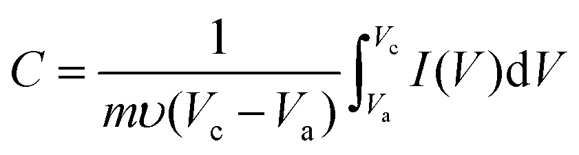
To evaluate the electrochemical properties of zinc cobalt oxides in supercapacitors, the performance of the as-prepared ZnCo2O4 nanoparticles were studied by cyclic voltammetry (CV), galvanostatic charge–discharge and cycling life measurements with a three-electrode system in a 6.0 M KOH solution. Fig. S7† shows the representative cyclic voltammetry (CV) curves of the three samples at various scan rates (5 mV s−1, 10 mV s−1, 20 mV s−1, 50 mV s−1, and 100 mV s−1) in a potential window from 0.05 to 0.45 V (vs. Ag/AgCl). A pair of well-defined redox peaks is visible in all of the CV curves as a result of the Faradic capacitive behaviour related to Co(OH)2/CoOOH. With increasing scan rate, the shapes of the CV curves do not significantly change except for a little shift in the peak position. This reveals the ideal capacitive behaviour of the ZnCo2O4 samples. Fig. 5a shows the comparison of the CV curves for electrodes 1, 2 and 3 at a scan rate of 5 mV s−1. From the three curves, we can see that the CV internal area for electrode 1 is the largest one and that for electrode 3 is the least one, which can be attributed to the higher surface area of compound 1 because this favours fast ionic transport in the electrodes. The capacitance of the ZnCo2O4 electrode at various scan rates can be calculated from the following equation:48
 | (1) |
 | ||
| Fig. 5 (a) Comparative CV curves recorded at a scan rate of 5 mV s−1 for 1, 2 and 3; (b) galvanostatic charge–discharge at a current density of 1 A g−1 for three electrodes; (c) specific capacitance derived from the discharging curves of the three electrodes; (d) long-term cycling stability of electrodes 1, 2 and 3 at a galvanostatic charge–discharge current density of 2 A g−1. | ||
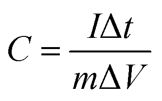
To further evaluate the application potential of the as-synthesised ZnCo2O4 samples as electrodes for electrical capacitors, a galvanostatic charge–discharge test was conducted in a stable potential window between 0.05 and 0.4 V (vs. Ag/AgCl) at various current densities ranging from 1 to 40 A g−1, as shown in Fig. S9.† A linear variation parallel to the vertical axis indicates pure double-layer capacitance behaviour; the slope variation caused by redox reactions indicates a typical pseudocapacitive behaviour. The specific capacitance of the electrodes at different current densities can be calculated using the following equation:48
 | (2) |
The long-term cycling stability of the ZnCo2O4 samples (electrodes 1, 2, and 3) is an important quality required for practical applications. Measured under galvanostatic charge–discharge at a current density of 2 A g−1, only a small capacitance drop is observed after 1500 cycles, as shown in Fig. 5d. The specific capacitances remain at about 425 F g−1 (97.9%), 313 F g−1 (96.8%), and 212 F g−1 (94.6%) for electrodes 1, 2 and 3, respectively. Fig. S10† shows the first and last 15th galvanostatic charge–discharge cycles for electrodes 1, 2 and 3, respectively. From the curves, we can see that the shapes of the first and the last 15th curves remain almost the same, revealing its excellent cycling capability.
Conclusions
In summary, a mixed-metal MOF, JUC-155, was successfully synthesised by a simple and time-saving method. By heating at 400 °C for two hours in air, JUC-155 can be fully converted to porous ZnCo2O4 nanoparticles and the resulting ZnCo2O4 can be applied as an electrode material for supercapacitors. The electrochemical results show that porous ZnCo2O4 samples display a specific capacitance as high as 450 F g−1 at a low scan rate (5 mV s−1) and maintain 97.9% of their initial capacitance after 1500 cycles. This study demonstrates the application of a mixed-metal MOF as a single precursor in the formation of mixed-metal oxides. This simple method can be readily extended to fabrication of other porous metal oxides for supercapacitors. More generally, by choosing suitable precursor MOFs, the obtained metal oxides may show potential applications in other fields, such as lithium ion batteries, magnets, and sensors.Acknowledgements
This work was supported by the National Natural Science Foundation of China (21390394), the National Basic Research Program of China (2012CB821700), NSFC (21261130584, 11227403, 21201076, and 21101072), “111” project (B07016), Award Project of KAUST (CRG-1-2012-LAI-009), and China Scholarship Council (CSC) for a scholarship (M.X.).Notes and references
- P. C. Chen, G. Z. Shen, H. T. Chen, Y. Shi and C. W. Zhou, ACS Nano, 2010, 4, 4404 Search PubMed
.
- G. P. Wang, L. Zhang and J. J. Zhang, Chem. Soc. Rev., 2012, 41, 797 RSC
- V. Subramanian, H. W. Zhu, R. Vajtai, P. M. Ajayan and B. Q. Wei, J. Phys. Chem. B, 2005, 109, 20207 CrossRef CAS PubMed
- C. Z. Yuan, L. Yang, L. R. Hou, L. F. Shen, X. G. Zhang and X. W. Lou, Energy Environ. Sci., 2012, 5, 7883 CAS
-
B. E. Conway, Electrochemical Supercapacitors: Scientific Fundamentals and Technological Applications, Kluwer Academic/Plenum Publishers, New York, 1999 Search PubMed
- P. Simon and Y. Gogotsi, Nat. Mater., 2008, 7, 845 CrossRef CAS PubMed
- S. W. Lee, B. M. Gallant, H. R. Byon, P. T. Hammond and S. H. Yang, Energy Environ. Sci., 2011, 4, 1972 CAS
- Y. P. Zhai, Y. Q. Dou, D. Y. Zhao, P. F. Fulvio, R. T. Mayes and S. Dai, Adv. Mater., 2011, 23, 4828 CrossRef CAS PubMed
- Z. Fan, J. H. Chen, K. Z. Cui, F. Sun, Y. Xu and Y. F. Kuang, Electrochim. Acta, 2007, 52, 2959 CrossRef CAS PubMed
- Z. Chen, Y. C. Qin, D. Weng, Q. F. Xiao, Y. T. Peng, X. L. Wang, H. X. Li, F. Wei and Y. F. Lu, Adv. Funct. Mater., 2009, 19, 3420 CrossRef CAS
- G. Lota, K. Fic and E. Frackowiak, Energy Environ. Sci., 2011, 4, 159 Search PubMed
- W. Sugimoto, H. Iwata, Y. Yasunaga, Y. Murakami and Y. Takasu, Angew. Chem., Int. Ed., 2003, 42, 4092 CrossRef CAS PubMed
- J. Jiang, Y. Y. Li, J. P. Liu, X. T. Huang, C. Z. Yuan and X. W. Lou, Adv. Mater., 2012, 24, 5166 CrossRef CAS PubMed
- C. Z. Yuan, H. B. Wu, Y. Xie and X. W. Lou, Angew. Chem., Int. Ed., 2013, 52, 2 Search PubMed
- Y. C. Qiu, S. H. Yang, H. Deng, L. M. Jin and W. S. Li, J. Mater. Chem., 2010, 20, 4439 RSC
- B. Liu, J. Zhang, X. F. Wang, G. Chen, D. Chen, C. W. Zhou and G. Z. Shen, Nano Lett., 2012, 12, 3005 CrossRef CAS PubMed
- K. Karthikeyan, D. Kalpana and N. G. Renganathan, Ionics, 2009, 15, 107 CrossRef CAS
- M. Davis, C. Gümeci, B. Black, C. Korzeniewski and L. H. Weeks, RSC Adv., 2012, 2, 2061 RSC
- F. X. Bao, X. F. Wang, X. D. Zhao, Y. Wang, Y. Ji, H. D. Zhang and X. Y. Liu, RSC Adv., 2014, 4, 2393–2397 RSC
- B. Liu, B. Y. Liu, Q. F. Wang, X. F. Wang, Q. Y. Xiang, D. Chen and G. Z. Shen, ACS Appl. Mater. Interfaces, 2013, 5, 10011–10017 CAS
- M. Eddaoudi, J. Kim, N. Rosi, D. Vodak, J. Wachter and O. M. Yaghi, Science, 2002, 295, 469 CrossRef CAS PubMed
- D. X. Xue, A. J. Cairns, Y. Belmabkhout, L. Wojtas, Y. Liu, M. H. Alkordi and M. Eddaoudi, J. Am. Chem. Soc., 2013, 135, 7660 CrossRef CAS PubMed
- Z. Y. Gu, J. Park, A. Raiff, Z. Wei and H. C. Zhou, Chem. Catal. Chem., 2013, 6, 67 Search PubMed
- S. Kitagawa, R. Kitaura and S. Noro, Angew. Chem., Int. Ed., 2004, 43, 2334 CrossRef CAS PubMed
- L. Pan, K. M. Adams, H. E. Hernandez, X. T. Wang, C. Zheng, Y. Hattori and K. J. Kaneko, J. Am. Chem. Soc., 2003, 125, 3062 CrossRef CAS PubMed
- L. J. Murray, M. Dincă and J. R. Long, Chem. Soc. Rev., 2009, 38, 1294 RSC
- Y. J. Cui, H. Xu, Y. F. Yue, Z. Y. Guo, J. C. Yu, Z. X. Chen, J. K. Cao, Y. Yang, G. D. Qian and B. L. Chen, J. Am. Chem. Soc., 2012, 134, 3979 CrossRef CAS PubMed
- H.-L. Jiang, B. Liu, Y.-Q. Lan, K. Kuratani, T. Akita, H. Shioyama, F. Q. Zhong and Q. Xu, J. Am. Chem. Soc., 2011, 133, 11854 CrossRef CAS PubMed
- B. Liu, H. Shioyama, H. L. Jiang, X. B. Zhang and Q. Xu, Carbon, 2010, 48, 456 CrossRef CAS PubMed
- L. Y. Chen, J. F. Bai, C. Z. Wang, Y. Pan, M. Scheer and X. Z. You, Chem. Commun., 2008, 1581 RSC
- F. Zhang, L. Hao, L. J. Zhang and X. G. Zhang, Int. J. Electrochem. Sci., 2011, 6, 2943 CAS
- F. Meng, Z. G. Fang, Z. X. Li, W. W. Xu, M. J. Wang, Y. P. Liu, J. Zhang, W. R. Wang, D. Y. Zhao and X. H. Guo, J. Mater. Chem., 2013, 24, 7235 RSC
- B. Liu, H. Shioyama, T. Akita and Q. Xu, J. Am. Chem. Soc., 2008, 130, 5390 CrossRef CAS PubMed
- L. Y. Chen, J. F. Bai, C. Z. Wang, Y. Pan, M. Scheer and X. Z. You, Chem. Commun., 2008, 1581 RSC
- X. D. Xu, R. G. Cao, S. Jeong and J. Cho, Nano Lett., 2012, 12, 4988 CrossRef CAS PubMed
- L. Zhang, H. B. Wu, S. Madhavi, H. H. Hng and X. W. Lou, J. Am. Chem. Soc., 2012, 134, 17388 CrossRef CAS PubMed
- J. Zhao, F. Q. Wang, P. P. Su, M. R. Li, J. Chen, Q. H. Yang and C. Li, J. Mater. Chem., 2012, 22, 13328 RSC
- P. Mahata, D. Sarma, C. Madhu, A. Sundaresen and S. Natarajan, Dalton Trans., 2011, 40, 1952 RSC
- D. Sarma, P. Mahata and S. Natarajan, Curr. Sci., 2012, 103, 1185 CAS
- R. B. Wu, X. K. Qian, K. Zhou, J. Wei, J. Lou and P. M. Ajayan, ACS Nano, 2014, 6, 6297 CrossRef PubMed
- M. Clemente-León, E. Coronado, C. Martí-Gastaldo and F. M. Romero, Chem. Soc. Rev., 2011, 40, 473 RSC
- C. K. Brozek and M. Dincă, J. Am. Chem. Soc., 2013, 135, 12886 CrossRef CAS PubMed
- M. Kim, J. F. Cahill, H. Fei, K. A. Prather and S. M. Cohen, J. Am. Chem. Soc., 2012, 134, 18082 CrossRef CAS PubMed
- M. C. Das, S. C. Xiang, Z. J. Zhang and B. L. Chen, Angew. Chem., Int. Ed., 2011, 50, 10510 CrossRef CAS PubMed
- W. Y. Gao, M. Chrzanowski and S. Q. Ma, Chem. Soc. Rev., 2014, 43, 5841 RSC
-
G. Sheldrick, SHELXS 97, Program for Crystal Structure Refinement, University of Gottingen, Gottingen, Germany, 1997 Search PubMed
- J. Kim, B. L. Chen, T. M. Reineke, H. L. Li, M. Eddaoidi, D. B. Moler, M. O'Keeffe and O. M. Yaghi, J. Am. Chem. Soc., 2001, 123, 8239 CrossRef CAS PubMed
- H. Pang, J. Deng, J. Du, S. Li, J. LI, Y. Ma, J. Zhang and J. Chen, Dalton Trans., 2012, 41, 10175 RSC
- C. Xu, B. Li, H. Du, F. Kang and Y. Zeng, J. Power Sources, 2008, 180, 664 CrossRef CAS PubMed
- Y. G. Wang and Y. Y. Xia, J. Electrochem. Soc., 2006, 153, A450 CrossRef CAS PubMed
Footnote |
| † Electronic supplementary information (ESI) available: Crystal data and additional figures. CCDC 1018100. For ESI and crystallographic data in CIF or other electronic format see DOI: 10.1039/c4qi00167b |
| This journal is © the Partner Organisations 2015 |