 Open Access Article
Creative Commons Attribution 3.0 Unported Licence
Synthesis of poly(spirosilabifluorene) copolymers and their improved stability in blue emitting polymer LEDs over non-spiro analogs†
Jeffrey J.
McDowell
,
Dong
Gao
,
Dwight S.
Seferos
and
Geoffrey
Ozin
*
Department of Chemistry, University of Toronto, 80 St. George Street, Toronto, ON M5S 3H6, Canada. E-mail: gozin@chem.utoronto.ca
First published on 1st April 2015
Abstract
We report herein a unique deep blue emitting copolymer, poly(3,6-dimethoxy-9.9′-dihexylsilafluorene-co-3.6-dimethoxy-2′,3′,6′,7′-tetrahexyloxy-9,9-spiro-9-silabifluorene) (PHSSF-co-PDHSF), which exhibits brilliant solid state blue luminescence, high quantum efficiency, excellent solubility and thermal stability. We have found that using PHSSF-co-PDHSF copolymers with large volume fractions of spirosilabifluorene as the emissive layer in OLEDs correlates to more stable EL intensity and have improved lifetimes over non-spiro poly(silafluorene) devices. The HSSF monomer is prepared via a two-part procedure, with each part resulting in one of two biphenyl segments which combines in a final cyclization step involving tetrachlorosilane. One segment possesses two bromide groups necessary for the polymerization. We utilized an efficient nickel catalyzed polymerization based on diarylmagnesate monomers to create PHSSF-co-PDHSF in good yield with number average molecular weights exceeding 50 kg mol−1 with a PDI = 1.8. The polymerization was complete in less than 30 min. For PHSSF-co-PDHSF OLED devices, the maximum irradiance of the device was 40 W m−2 at a current density of 60 mA cm−2 and EL maximum centered at 410 nm. The maximum device external quantum efficiency was 2.9% when operating at 38 mA cm−2. To measure OLED stability, we monitored normalized EL intensity for both PHSSF-co-PDHSF and PDHSF devices. Over the course of 10 h, the EL intensity of the PDHSF device drops 20% more than the PHSSF-co-PDHSF device when operating at 6 mA cm−2
Introduction
Integrating nonplanar “spiro” compounds1–22 into organic electronics shows promise for improving properties which are important for the efficient operation of devices such as organic light-emitting diodes (OLEDs),5–9 organic phototransistors (OPTs),10,11 organic solid-state lasers (OSSLs),12–15 as well as organic thin film transistors (OTFTs).16,17 Such properties include morphological, thermal and chemical stability, superior isolation of emitting centers and hence enhanced photo/electroluminescent quantum efficiencies, better solubility and improved solution processability.18–22 Compounds which are considered “spiro” consist of two orthogonally arranged subsections centered on a tetravalent atom. There are many examples of symmetric as well as asymmetric spiro compounds in the literature, many common examples are spirobifluorenes (SF) derivatives.23–27 SFs are rigid 3D structures due to the lack of rotational freedom of orthogonal fluorene subunits, the molecular structure of spirobifluorenes effectively disrupts regular crystalline packing and results in films which have solution like photophyiscal properties.28–30 Consequently, SFs are an increasing important class of compound used in the design of new solid state chromophores with improved performance over simpler fluorene derivatives which show a higher tendency to crystallize and hence exhibit reduced PL efficiency.31,32 The appealing electronic and optical properties of other SF derivatives, including spiro-MeOTAD, has prompted their use in solar energy conversion as a charge transport material in, for example, dye sensitized solar cells.33,34 The silicon analogs of SFs, spirosilabifluorenes (SSFs), have unique characteristics which distinguish them as subsets of the newly explored class of compounds called siloles.35–41 Siloles, as well as silafluorenes and spirosilabifluorenes, are becoming increasingly popular components in organic electronics due to their brilliant solid state blue luminescence and superior electron conductivity.42–46 The higher electron affinity and conductivity, which is particularly promising for OLEDs, originates from σ*–π* conjugation between the σ* antibonding orbital of the exocyclic Si–C bond and the π* antibonding orbital of the butadiene fragment.47Evidence for this phenomenon is obtained by measuring atypical bathochromic shifts in silole absorption spectrum and comparing results to corresponding carbon analogues.48 Kafafi et al. have reported a series of asymmetrically aryl-substituted 9,9′-spiro-9-silabifluorene derivatives which were prepared via the cyclization of the 2,2′-dilithiobiphenyls with silicon tetrachloride.48 These materials form amorphous films which are both transparent and stable due to a relatively high glass transition temperatures (Tg = 203–228 °C). Solid state films of their materials were reported to have an intense violet-blue emission (λem = 398–415 nm) with high absolute photoluminescence quantum yields of 30–55%. For many siloles, high PL efficiency can be attributed to a phenomenon known as aggregation induced emission (AIE).49 AIE compounds have significant potential as gain medium in solid state organic lasers in addition to light-emitting materials in OLEDs. In the latter case, SSFs have already shown impressive performance with OLED electroluminescence external quantum efficiencies as high as ηeff = 4.8% (at 10 mA cm−2).50 Many low molecular weight siloles, however, crystallize readily, contributing to device degradation when these materials are incorporated in OLED structures.51 In an attempt to prevent this issue, we have prepared a unique deep blue emitting copolymer, poly(3,6-dimethoxy-9.9′-dihexylsilafluorene-co-3.6-dimethoxy-2′,3′,6′,7′-tetrahexyloxy-9,9-spiro-9-silabifluorene) (PDHSF-co-PHSSF), with a spirosilabifluorene repeat unit (10), which we expected to exhibit high glass transition temperatures, improved solid-state PL quantum yields and have superior OLED performance. As we will later demonstrate, a large volume fraction of spirosilabifluorene leads to EL intensities of working OLEDs being measurably more stable with improved lifetimes over non-spiro poly(silafluorenes) devices.
Results and discussion
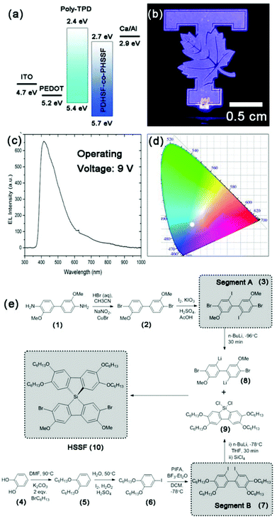
Fig. 1e illustrates the synthetic steps taken to create our spirosilabifluorene monomer. To the best of our knowledge, there has been no prior attempt to polymerize SSFs and hence no polymer LEDs have been constructed using PSSFs. The synthesis is two-part, each resulting in a segment (referred to as segment A and B) which combines in a final cyclization step involving tetrachlorosilane. Segment A possesses two bromide groups necessary for the polymerization, details of which will be discussed below. Its synthesis begins with commercially available o-dianisidine (1) starting material which is easily converted to (2) by the reaction of an intermediate bis(diazonium) salt with CuBr (the latter is produced in situ by the oxidation of (1) by NaNO2). Iodination of (2) is directed at carbons C5 and C5′ by the electron donating methoxy groups at C3 and C3′. Yields of both reactions are high, averaging 85% for the Sandmeyer bromination deamination and 80% for the iodination.Notable features of segment B include four hexyloxy groups installed to increase solubility of the monomer and resultant polymer. Segment B is also the product of several high yielding steps beginning with catechol (4). Both hydroxyl groups are converted to hexyloxy following reflux with 1-bromohexanes in DMF. Following purification, (5) undergoes a single iodination after being stirred in an aqueous solution (acidified with H2SO4) with a slight access of I2 and H2O2 oxidant. 1-Iodo-3,4-dihexyloxybenzene (6) was collected as a pure liquid, the last fraction of a vacuum distillation which efficiently separates it from non-iodonated starting materials. To obtain the biphenyl (7), a unique aryl coupling procedure was used involving the reaction of (6) with the hypervalent iodine complex phenyliodine bis(trifluoroacetate), PIFA, in the presence of a yield improving additive BF3–Et2O. The mechanism by which aryl coupling occurs has been the subject of numerous reviews.53,54 This exothermic reaction is performed whilst cooling with a dry ice/acetone bath to control the rate, which is high despite the low temperature. Product is formed readily by the time the reaction warms to room temperature. Pure (7) is obtained by crystallization at low temperatures from hexanes. The product forms white, blocky crystals which readily dissolve in organic solvents. Lithiation is performed at low temperatures using an acetone/dry ice bath by dissolving (7) in THF and adding two equivalence of n-butyl lithium. The metathesis is quantitative within a few minutes.
The first of two cyclization reactions begins with a duel substitution reaction involving lithiated (7) and SiCl4 to form two LiCl and the ring-closed dichlorosilafluorene (9). Because the rate of substitution is quiet high, the order of addition is crucial to avoiding large amounts of unwanted symmetric spirosilabifluorenes. While maintaining a low temperature for both solutions, the soluble dilithiated (7) is added to a separate solution of SiCl4 in THF. The reaction is complete by the time the solution warms to room temperature. Solvent is removed in vacuo from the moisture sensitive (9) and the crude product residue is redissolved in dry hexanes and cooled to precipitate out less soluble by-products. Removal of hexanes yields the pure dichlorosilafluorene segment and concentrated THF solutions of this compound can be stored for long periods of time with refrigeration. 29Si NMR of (9) shows a single peak at 5.8 ppm, confirming the purity of the intermediate (see ESI†).
To complete the second cyclization and generate the final spirosilabifluorene monomer, segment A is reacted with two equivalence of n-BuLi in an analogous manner to the reaction with (7). However, it is necessary to maintain the temperature of this reaction at −100 °C (using a nitrogen/MeOH slush bath) throughout the lithiation step to ensure selectivity for iodide while both bromide groups remain unreacted. A concentrated solution of the dichlorosilafluorene (9) in THF equalling one equivalence with respect to (8), is added and the final product is purified by crystallization from hexanes. Fig. 2 shows the 1H NMR of 2.7-dibromo-3.6-dimethoxy-2′,3′,6′,7′-tetrahexyloxy-9,9-spiro-9-silabifluorene (10). Additionally, 29Si NMR of this compound consists of a single resonance peak at −8.6 ppm belonging to the pure product. Complete characterization of (10) can be found in the Experimental section and ESI.†
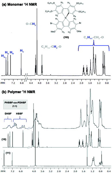 | ||
Fig. 2 (a) 1H NMR of monomer (10) (purified by crystallization from hexanes) and assignment of peaks. (b) 1H NMR of copolymer PHSSF-co-PDHSF as well as the spectra of each monomer (for comparison). Broad aromatic peaks between 7.4–7.6 ppm belong to DHSF repeat units (as reported previously52). Integration of this broad set of peaks with respect to the remaining collection of four HSSF peaks gives an estimate of 1![[thin space (1/6-em)]](https://www.rsc.org/images/entities/char_2009.gif) : :![[thin space (1/6-em)]](https://www.rsc.org/images/entities/char_2009.gif) 1 DHSF to HSSF repeat units (Fig. S1.9.0 in ESI†). 1 DHSF to HSSF repeat units (Fig. S1.9.0 in ESI†). | ||
Prior to polymerization, the dibromide HSSF premonomer (10) converted to its respective diarylmagnesates by Grignard metathesis. The highest rate of conversion was obtained when using a mixed solvent system consisting of 30% 1,4-dioxane in tetrahydrofuran. Within 2 h, >95% of HSSF was converted to bis(bromo-3,6-dimethoxy-2′,3′,6′,7′-tetrahexyloxy-9,9-spiro-9-silabifluorene)magnesate (12). In a separate reaction, 2,7-dibromo-3,6-dimethoxy-9,9-dihexylsilafluorene was converted to its respective diarylmagnesate (11) under identical conditions. In both reactions, formation of an insoluble MgCl2-dioxane adduct is obvious from the precipitation of a fine white solid within a few seconds of adding iPrMgCl-LiCl.
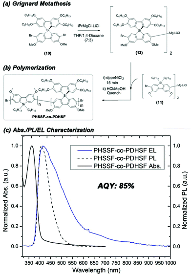
We utilized an efficient nickel catalyzed polymerization based on diarylmagnesate monomers to create copolymers of (11) and (12) with roughly half of the repeat units derived from (11) (as determined by integration of respective aromatic 1H NMR peaks and peaks of both monomer Si peaks in the 29Si HMBC, see ESI Fig. S1.9.0–S1.9.2†). PHSSF-co-PDHSF (13) was produced in good yield with number average molecular weights exceeding 50 kg mol−1 with a PDI = 1.8 (similar molecular weights were obtained for the DHSF homopolymer (52 kg mol−1; PDI = 1.7, see ESI S2.1.0–S2.2.0†). The polymerization was complete in less than 30 min and polymerization was quenched by adding HCl followed by precipitation in methanol. Excess monomer and oligomers were removed by subsequent soxhlet extraction with EtOH over a period of 5–6 h. Fig. 3a and b illustrates the reaction conditions used in the polymerization. Fig. 2b shows a representative 1H NMR of the purified polymer.
Initial thermal analysis of the copolymer using TGA/DSC indicates the material is stable under nitrogen up to a temperature of 350 °C, Fig. 4. Morphologically, there were no obvious phase transitions occurring within the temperature region of 25–250 °C over numerous cycles. PSFs are known for their thermal stability, and our initial findings seem to indicate that adding HSSF into the polymer backbone does nothing if not improve this quality.55–57
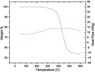 | ||
| Fig. 4 TGA/DSC of PHSSF-co-PDHSF over the temperature range 25–200 °C. No Tg or Tm phase changes occur over multiple cycles. | ||
The HOMO energy of the PHSSF-co-PDHSF copolymer was determined using cyclic voltammetry and the bandgap was determined from the solid-state absorption onset (CV can be found in ESI† and absorption spectrum is shown Fig. 3c). It was found that HOMO/LUMO energy levels (5.7 eV and 2.7 eV respectively) are identical to those reported earlier by our group for similar polysilafluorene.52
Light emitting devices were constructed in a N2 filled glovebox on O2 plasma treated ITO on glass. We employed a simple trilayer design using PEDOT:PSS as the hole injection layer (∼10 nm) as well as a thin hole transport layer consisting of poly-TPD (∼20 nm). A 100 nm emissive layer consisting of PHSSF-co-PDHSF was deposited by spin casting from a 10 mg mL−1 polymer solution in toluene. A Ca cathode, which best matches the copolymer LUMO energy of 2.7 eV, was found to yield the best performing devices. Fig. 1a illustrates the device architecture and energy levels of the respective layers. A photograph of a functioning device operating at 9 V is shown in Fig. 1b. A respective electroluminescence spectrum is shown in Fig. 1c. The EL peak maximum is nearly identical to the thin film PL spectra at ∼410 nm. However, the FWHM of the EL emission is noticeably larger than the solid-state PL, Fig. 3c. Fig. 1d shows the location of the device's blue-violet emission on the CIE colour map with coordinates of x = 0.246 and y = 0.237.
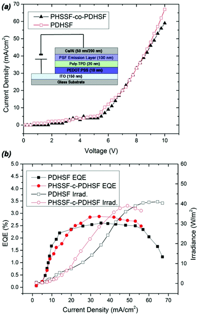
Performance data obtained from devices with PHSSF-co-PDHSF and PDHSF emissive layers is presented in Fig. 5. PDHSF OLEDs were created for the purpose of comparison and to establish the impact of spirosilabifluorene on performance. The OLEDs tested both have 0.25 cm2 emissive areas. Referring to the I–V curve, we observe the turn on voltage to be roughly 5 V in both devices. This is not surprising given the energy levels of both emissive materials are essentially identical. Both devices were operated up to 10 V and each reached a maximum current density of ∼65 mA cm−2. For the PHSSF-co-PDHSF device, the maximum irradiance of the device was 40 W m−2 at a current density of 60 mA cm−2. The maximum efficiency of the device, in terms of EQE, was 2.9% when operating at 38 mA cm−2. Likewise, the PDHSF device operated at a maximum irradiance of 38 W m−2 at a current density of 45 mA cm−2. The maximum efficiency of the device was 2.5% when operating at 30 mA cm−2.
Over extended device operation times, however, a significant difference in performance emerges. Fig. 6 plots the averaged EL intensity for the different devices over a period of 10 h (the data set consists of six total devices, with three of each type). When operating with a current density of 6 mA cm−2, both device types show a gradual decline in EL intensity. The slope of the PHSSF-co-PDHSF device, however, is noticeably less than the PDHSF device. We posit the reason for such a noticeable deviation is the spirosilabifluorene unit. The inclusion of this rigid 3D structure in the polymer backbone leads to reduced interaction between neighbouring chains, preventing the degenerative effects of crystallization and excimer formation resulting in an overall increase in electroluminescent yield over a longer time frame.
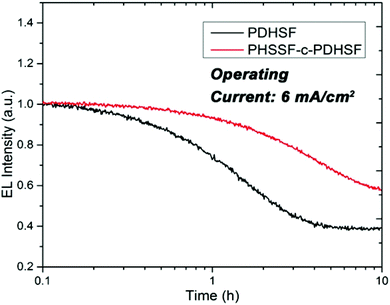 | ||
| Fig. 6 Plot of the EL intensity for both PHSSF-co-PDHSF and PDHSF devices. Over the course of 10 h, the EL intensity of the PDHSF device drops 20% more than the PHSSF-co-PDHSF device. | ||
Conclusions
In future work, we intend to increase the number of copolymers produced by this method with the aim of producing stable blue, green and red emitters for light emitting technologies. It would also be of considerable interest to combine the promising performance of these copolymers with the additional functionality of photocrosslinkable versions of PSF which our group has previously reported on.58 Ultimately the goal is to develop longer lasting emitters which can be photolithographically patterned to allow for solution processed full colour thin-film displays driven by TFT backplanes as well combining multiple long lifetime polymer emitters to produce solution processed WOLEDs.Experimental
All syntheses were performed under inert atmosphere using standard schlenk line or glovebox techniques unless otherwise stated. Chemicals were purchased from TCI America and Sigma Aldrich and used without need for further purification. Tetrahydrofuran and 1,4-dioxane were distilled over sodium/benzophenone prior to use. Proton, carbon and silicon NMR were performed on a 400 MHz Bruker Avance III Spectrometer. Solution and thin film absorption and photoluminescence spectra were recorded using a Perkin-Elmer 900 UV-Vis Spectrometer and a Perkin-Elmer LS-50B Luminescence Spectrophotometer. Polymer quantum efficiencies were calculated through the use of an integrating sphere using a focused 365 nm LED as the excitation source.59 Polymer molecular weights were measured with a Viscotek GPC calibrated with respect to polystyrene standards using THF as an eluent and column temperature of 35 °C. Cyclic voltammetry was performed on polymer samples in a solution of 100 mM tetrabutylammonium hexafluorphosphate in dichloromethane (distilled from CaH2 under N2 prior to measurement). Potentials were measured using a Solartron 1278 potentiostat using platinum working and counter electrodes in addition to a Ag/AgCl pseudo reference electrode. Measurements were calibrated using ferrocene as an internal standard. Thermogravometric and calorimetric data was acquired using a TA Instruments SDT Q600 simultaneous TGA/DSC system operated under an inert N2 atmosphere. Poly(3,6-dimethoxy-9,9-dihexylsilafluorene) (PDHSF) was prepared using a previously published procedure.52HSSF monomer synthesis
Polymer synthesis
![[thin space (1/6-em)]](https://www.rsc.org/images/entities/char_2009.gif) :
:![[thin space (1/6-em)]](https://www.rsc.org/images/entities/char_2009.gif) 0.7 (DHSF
0.7 (DHSF![[thin space (1/6-em)]](https://www.rsc.org/images/entities/char_2009.gif) :
:![[thin space (1/6-em)]](https://www.rsc.org/images/entities/char_2009.gif) HSSF) (see ESI S1.9.0–S1.9.2†). 1H/13C NMR and assignments for the DHSF monomer is presented in Fig. S1.8.0–S1.8.2 in the ESI.†1H NMR data is also provided for the PDHSF homopolymer for comparison.
HSSF) (see ESI S1.9.0–S1.9.2†). 1H/13C NMR and assignments for the DHSF monomer is presented in Fig. S1.8.0–S1.8.2 in the ESI.†1H NMR data is also provided for the PDHSF homopolymer for comparison.
Electroluminescent device fabrication
OLEDs were prepared using prepatterned ITO substrates (7 ohm sq−1, Visiontek Inc.) which were cleaned using O2 plasma for a period of 5 min. PEDOT:PSS (AL4083, Clevios) was diluted (1![[thin space (1/6-em)]](https://www.rsc.org/images/entities/char_2009.gif) :
:![[thin space (1/6-em)]](https://www.rsc.org/images/entities/char_2009.gif) 1 v/v) with DI water prior to spin casting at 3000 rpm for 2 min (acceleration was set to 1000 rpm s−1). The substrates were transferred to a N2 filled glovebox and dried by heating at 110 °C for 30 min on a hotplate. All subsequent processing was done under N2. Once cooled, a hole injection layer (HIL) was deposited by spin casting a 10 mg mL−1 chlorobenzene poly-TPD (American Dye Source) solution at 2000 rpm for 2 min (acceleration = 1000 rpm s−1). The HIL layer was dried by baking the substrate at 150 °C for 30 min. Once cooled, the emissive polymer layer (either (PHSSF-co-PDHSF) or (PDHSF)) was deposited by spincasting an 10 mg mL−1 toluene solution at 1000 rpm for 2 min (acceleration = 1000 rpm s−1). The substrate was placed in the glovebox antechamber and dried under vacuum for a period of 30 min prior to depositing a Ca/Al cathode. The optimal Ca layer thickness was 50 nm (deposited at a rate of 0.8 Å s−1). The Al layer thickness was 200 nm (deposited at a rate of 1 Å s−1). I–V–L device characteristics were measured following the encapsulation of the OLEDs to protect them from degradation. Radiance of each pixel (as a function of applied bias) was measured using a Keithley 2400 SourceMeter and a calibrated integrating sphere coupled to a fiber spectrometer.
1 v/v) with DI water prior to spin casting at 3000 rpm for 2 min (acceleration was set to 1000 rpm s−1). The substrates were transferred to a N2 filled glovebox and dried by heating at 110 °C for 30 min on a hotplate. All subsequent processing was done under N2. Once cooled, a hole injection layer (HIL) was deposited by spin casting a 10 mg mL−1 chlorobenzene poly-TPD (American Dye Source) solution at 2000 rpm for 2 min (acceleration = 1000 rpm s−1). The HIL layer was dried by baking the substrate at 150 °C for 30 min. Once cooled, the emissive polymer layer (either (PHSSF-co-PDHSF) or (PDHSF)) was deposited by spincasting an 10 mg mL−1 toluene solution at 1000 rpm for 2 min (acceleration = 1000 rpm s−1). The substrate was placed in the glovebox antechamber and dried under vacuum for a period of 30 min prior to depositing a Ca/Al cathode. The optimal Ca layer thickness was 50 nm (deposited at a rate of 0.8 Å s−1). The Al layer thickness was 200 nm (deposited at a rate of 1 Å s−1). I–V–L device characteristics were measured following the encapsulation of the OLEDs to protect them from degradation. Radiance of each pixel (as a function of applied bias) was measured using a Keithley 2400 SourceMeter and a calibrated integrating sphere coupled to a fiber spectrometer.
Acknowledgements
GAO is Government of Canada Research Chair in Materials Chemistry and Nanochemistry. JM is an NSERC Graduate Fellow. Both are deeply indebted to the Natural Sciences and Engineering Research Council for strong and sustained support of their work.Notes and references
- P. I. Saragi, T. Spehr, A. Siebert, T. Fuhrmann-Lieker and J. Salbeck, Chem. Rev., 2007, 107, 1011 CrossRef PubMed.
- R. Pudzich, T. Fuhrmann-Lieker and J. Salbeck, Adv. Polym. Sci., 2006, 199, 83 CrossRef CAS.
- J. Pei, J. Ni, X. H. Zhou, X. Y. Cao and Y. H. Lai, J. Org. Chem., 2002, 67, 8104 CrossRef CAS PubMed.
- U. Mitschke and P. J. Bauerle, J. Chem. Soc., Perkin Trans. 1, 2001, 740 RSC.
- C. Adachi, T. Tsutsui and S. Saito, Appl. Phys. Lett., 1989, 55, 1489 CrossRef CAS PubMed.
- H. Spreitzer, H. Schenk, J. Salbeck, F. Weissortel, H. Riel and W. Riess, Proc. SPIE-Int. Soc. Opt. Eng., 1999, 3797, 316 CrossRef CAS PubMed.
- J. Y. Shen, C. Y. Lee, T. H. Huang, J. T. Lin, Y. T. Tao, C. H. Chien and C. Tsai, J. Mater. Chem., 2005, 15, 2455 RSC.
- M. Pfeiffer, K. Leo, X. Zhou, J. S. Hunag, M. Hofmann, A. Werner and J. Blochwitz-Nimoth, Org. Electron., 2003, 4, 89 CrossRef CAS PubMed.
- H. S. Chen, F. I. Wu, C. F. Shu, C. H. Chien and Y. T. Tao, J. Mater. Chem., 2004, 14, 1585 RSC.
- T. P. I. Saragi, R. Pudzich, T. Fuhrmann and J. Salbeck, Appl. Phys. Lett., 2004, 84, 2334 CrossRef CAS PubMed.
- T. P. I. Saragi, R. Pudzich, T. Fuhrmann-Lieker and J. Salbeck, Opt. Mater., 2007, 29, 879 CrossRef CAS PubMed.
- D. Schneider, T. Rabe, T. Riedl, T. Dobbertin, M. Kroeger, E. Becker, H. H. Johannes, W. Kowalsky, T. Weimann, J. Wang and P. Hinze, Appl. Phys. Lett., 2004, 85, 1659 CrossRef CAS PubMed.
- D. Schneider, T. Rabe, T. Riedl, T. Dobbertin, O. Werner, M. Kroger, E. Becker, H. H. Johannes, W. Kowalsky, T. Weimann, J. Wang, P. Hinze, A. Gerhard, P. Stossel and H. Vestweber, Appl. Phys. Lett., 2004, 84, 4693 CrossRef CAS PubMed.
- D. Schneider, T. Rabe, T. Riedl, T. Dobbertin, M. Kroger, E. Becker, H. H. Johannes, W. Kowalsky, T. Weimann, J. Wang and P. Hinze, J. Appl. Phys., 2005, 98, 043104 CrossRef PubMed.
- N. Johansson, J. Salbeck, J. Bauer, F. Weissortel, P. Broms, A. Andersson and W. R. Salaneck, Adv. Mater., 1998, 10, 1136 CrossRef CAS.
- T. P. I. Saragi, T. Fuhrmann-Lieker and J. Salbeck, Adv. Funct. Mater., 2006, 16, 966 CrossRef CAS PubMed.
- T. P. I. Saragi, T. Fuhrmann-Lieker and J. Salbeck, Synth. Met., 2005, 148, 267 CrossRef CAS PubMed.
- C. Hosokawa, H. Higashi, H. Nakamura and T. Kusumoto, Appl. Phys. Lett., 1995, 67, 3853 CrossRef CAS PubMed.
- T. Spehr, R. Pudzich, T. Fuhrmann and J. Salbeck, Org. Electron., 2003, 4, 61 CrossRef CAS PubMed.
- J. Salbeck, N. Yu, J. Bauer, F. Weissortel and H. Bestgen, Synth. Met., 1997, 91, 209 CrossRef CAS.
- J. Salbeck, F. Weissoertel and J. Bauer, Macromol. Symp., 1997, 125, 121 CrossRef PubMed.
- H. Lee, J. Oh, H. Y. Chu, J. I. Lee, S. H. Kim, Y. S. Yang, G. H. Kim, L. M. Do, T. Zyung, J. Lee and Y. Park, Tetrahedron, 2003, 59, 2773 CrossRef CAS.
- S. Tao, Z. Peng, X. Zhang, P. Wang, C. S. Lee and S. T. Lee, Adv. Funct. Mater., 2005, 15, 1716 CrossRef CAS PubMed.
- J. P. Choi, K. T. Wong, Y. M. Chen, J. K. Yu, P. T. Chou and A. J. Bard, J. Phys. Chem. B, 2003, 107, 14407 CrossRef CAS.
- C. C. Wu, Y. T. Lin, H. H. Chiang, T. Y. Cho, C. W. Chen, K. T. Wong, Y. L. Liao, G. H. Lee and S. M. Peng, Appl. Phys. Lett., 2002, 81, 577 CrossRef CAS PubMed.
- F. Fungo, K. T. Wong, S. Y. Ku, Y. Y. Hung and A. J. Bard, J. Phys. Chem. B, 2005, 109, 3984 CrossRef CAS PubMed.
- K. T. Wong, S. Y. Ku, Y. M. Cheng, X. Y. Lin, Y. Y. Hung, S. C. Pu, P. T. Chou, G. H. Lee and S. M. Peng, J. Org. Chem., 2006, 71, 456 CrossRef CAS PubMed.
- J. Salbeck, M. Schorner and T. Fuhrmann, Thin Solid Films, 2002, 417, 20 CrossRef CAS.
- T. Spehr, A. Siebert, T. Fuhrmann-Lieker, S. Salbeck, T. Rabe, T. Riedl, H. H. Johannes, W. Kowalsky, J. Wang, T. Weimann and P. Hinze, Appl. Phys. Lett., 2005, 87, 161103 CrossRef PubMed.
- R. Pudzich and J. Salbeck, Synth. Met., 2003, 138, 21 CrossRef CAS.
- U. Lemmer, S. Heun, R. F. Mahrt, U. Scherf, M. Hopmeier, U. Siegner, E. O. Goebel, K. Muellen and H. Bässler, Chem. Phys. Lett., 1995, 240, 373 CrossRef CAS.
- M. Grell, D. D. C. Bradley, G. Ungar, J. Hill and K. S. Whitehead, Macromolecules, 1999, 32, 5810 CrossRef CAS.
- U. Bach, D. Lupo, P. Comte, J. E. Moser, F. Weissortel, J. Salbeck, H. Spreitzer and M. Gratazel, Nature, 1998, 395, 583 CrossRef CAS PubMed.
- U. Bach, Y. Tachibana, J. E. Moser, S. A. Haque, J. R. Durrant, M. Gratzel and D. R. Klug, J. Am. Chem. Soc., 1999, 121, 7445 CrossRef CAS.
- K. Tamao, M. Uchida, T. Izumizawa, K. Furukawa and S. Yamaguchi, J. Am. Chem. Soc., 1996, 118, 11974 CrossRef CAS.
- S. Yamaguchi, T. Endo, M. Uchida, T. Izumizawa, K. Furukawa and K. Tamao, Chem. – Eur. J., 2000, 6, 1683 CAS.
- N. J. Watkins, A. J. Makinen, Y. Gao, M. Uchida and Z. H. Kafafi, Proc. SPIE Int. Soc. Opt. Eng., 2004, 5214, 368 CrossRef CAS PubMed.
- L. C. Palilis, H. Murata, M. Uchida and Z. H. Kafafi, Org. Electron, 2003, 4, 113 CrossRef CAS PubMed.
- M. Uchida, T. Izumizawa, T. Nakano, S. Yamaguchi, K. Tamao and K. Furukawa, Chem. Mater., 2001, 13, 2680 CrossRef CAS.
- H. Murata, G. G. Malliaras, M. Uchida, Y. Shen and Z. H. Kafafi, Chem. Phys. Lett., 2001, 339, 161 CrossRef CAS.
- L. C. Palilis, M. Uchida and Z. H. Kafafi, IEEE J. Sel. Top. Quantum Electron., 2004, 10, 79 CrossRef CAS.
- H. Gilman and R. D. Gorsich, J. Am. Chem. Soc., 1958, 80, 1883 CrossRef CAS.
- L. S. Chang and J. Y. Corey, Organometallics, 1989, 8, 1885 CrossRef CAS.
- B. H. Boo, J. Park, H. G. Yeo, S. Y. Lee, C. J. Park and J. H. Kim, J. Phys. Chem. A, 1998, 102, 1139 CrossRef CAS.
- D. Ballweg, Y. Liu, I. A. Guzei and R. West, Silicon Chem., 2002, 1, 57 CrossRef CAS.
- C. W. Keyworth, K. L. Chan, J. G. Labram, T. D. Anthopoulos, S. E. Watkins, M. McKiernan, A. J. P. White, A. B. Holmes and C. K. Williams, J. Mater. Chem., 2011, 21, 11800 RSC.
- I. B. Berlman, J. Chem. Phys., 1970, 52, 5616 CrossRef CAS PubMed.
- S. Lee, B. Jang and Z. Kafafi, J. Am. Chem. Soc., 2005, 127, 9071 CrossRef CAS PubMed.
- J. Chen, C. C. W. Law, J. W. Y. Lam, Y. Dong, S. M. F. Lo, I. D. Williams, D. Zhu and B. Z. Tang, Chem. Mater., 2003, 15, 1535 CrossRef CAS.
- L. C. Palilis, A. J. Makinen, M. Uchida and Z. H. Kafafi, Appl. Phys. Lett., 2003, 82, 2209 CrossRef CAS PubMed.
- H. Murata, Z. H. Kafafi and M. Uchida, Appl. Phys. Lett., 2002, 80, 189 CrossRef CAS PubMed.
- J. McDowell, I. Schick, A. Price, D. Faulkner and G. Ozin, Macromolecules, 2013, 46, 6794 CrossRef CAS.
- T. Dohi, M. Ito, K. Morimoto, M. Iwata and Y. Kita, Angew. Chem., Int. Ed., 2008, 47, 1301 CrossRef CAS PubMed.
- Y. Kita, K. Morimoto, M. Ito, C. Ogawa, A. Goto and T. Dohi, J. Am. Chem. Soc., 2009, 131, 1668 CrossRef CAS PubMed.
- W. W. H. Wong, J. Hooper and A. B. Holmes, Aust. J. Chem., 2009, 62, 393 CAS.
- K. L. Chan, M. J. McKiernan, C. R. Towns and A. B. Holmes, J. Am. Chem. Soc., 2005, 127, 7662 CrossRef CAS PubMed.
- K. L. Chan, S. E. Watkins, C. S. K. Mak, M. J. McKiernan, C. R. Towns, S. I. Pascu and A. B. Holmes, Chem. Commun., 2005, 5766 RSC.
- J. McDowell, F. Flaig-Maier, T. J. A. Wolf, A.-N. Unterreiner, U. Lemmer and G. Ozin, ACS Appl. Mater. Interfaces, 2014, 6, 83 CAS.
- J. C. deMello, H. F. Wittmann and R. H. Friend, Adv. Mater., 1997, 9, 230 CrossRef CAS PubMed.
- R.-F. Chen, Q.-L. Fan, C. Zheng and W. Huang, Org. Lett., 2006, 8, 203 CrossRef CAS PubMed.
- A. I. Vogel, A. R. Tatchell, B. S. Furnis, A. J. Hannaford and P. W. G. Smith, Vogel's Textbook of Practical Organic Chemistry, Prentice Hall, NY, 5th edn, 1996 Search PubMed.
Footnote |
| † Electronic supplementary information (ESI) available: Complete 1H, 29Si and 13C NMR spectra and polymer CV and GPC data. See DOI: 10.1039/c4py01418a |
| This journal is © The Royal Society of Chemistry 2015 |

