
 Open Access Article
 This Open Access Article is licensed under a Creative Commons Attribution-Non Commercial 3.0 Unported Licence
Adiabatic burst evaporation from bicontinuous nanoporous membranes
Sachar
Ichilmann
a,
Kerstin
Rücker
a,
Markus
Haase
a,
Dirk
Enke
b,
Martin
Steinhart
*a and
Longjian
Xue
*a
aInstitut für Chemie neuer Materialien and Zentrum für Physik und Chemie neuer Materialien, Universität Osnabrück, Barbarastr. 7, 49069 Osnabrück, Germany. E-mail: martin.steinhart@uos.de; longjian.xue@uos.de
bUniversität Leipzig, Institut für Technische Chemie, Linnestr. 3-4, 04103 Leipzig, Germany
First published on 22nd April 2015
Abstract
Evaporation of volatile liquids from nanoporous media with bicontinuous morphology and pore diameters of a few 10 nm is an ubiquitous process. For example, such drying processes occur during syntheses of nanoporous materials by sol–gel chemistry or by spinodal decomposition in the presence of solvents as well as during solution impregnation of nanoporous hosts with functional guests. It is commonly assumed that drying is endothermic and driven by non-equilibrium partial pressures of the evaporating species in the gas phase. We show that nearly half of the liquid evaporates in an adiabatic mode involving burst-like liquid-to-gas conversions. During single adiabatic burst evaporation events liquid volumes of up to 107 μm3 are converted to gas. The adiabatic liquid-to-gas conversions occur if air invasion fronts get unstable because of the built-up of high capillary pressures. Adiabatic evaporation bursts propagate avalanche-like through the nanopore systems until the air invasion fronts have reached new stable configurations. Adiabatic cavitation bursts thus compete with Haines jumps involving air invasion front relaxation by local liquid flow without enhanced mass transport out of the nanoporous medium and prevail if the mean pore diameter is in the range of a few 10 nm. The results reported here may help optimize membrane preparation via solvent-based approaches, solution-loading of nanopore systems with guest materials as well as routine use of nanoporous membranes with bicontinuous morphology and may contribute to better understanding of adsorption/desorption processes in nanoporous media.
1 Introduction
Evaporation of liquids from nanoporous membranes with bicontinuous morphology and pore diameters below 100 nm, such as mesoporous oxide materials, controlled porous glasses (CPGs)1 and polymer membranes, is an ubiquitous process of tremendous scientific and technical importance. For example, drying of gel bodies is a crucial step in sol–gel syntheses of microporous and mesoporous monoliths consisting of inorganic oxides.2–5 Moreover, the production of nanoporous polymer membranes by thermally-induced phase separation6 and by swelling-induced morphology reconstruction7,8 inevitably involves drying processes. Solvent evaporation is, furthermore, a crucial step in the loading of nanoporous hosts with functional guest materials by solution impregnation9 that sensitively influences the spatial distribution of functional guests within nanoporous hosts. However, the understanding of many aspects of liquid evaporation from nanoporous media is still at a premature stage. In particular, it is commonly assumed that evaporation at temperatures below the boiling point of the evaporating liquid is endothermic and driven by non-equilibrium vapor pressure of the evaporating species in the gas phase. Moreover, the slopes of desorption branches in nitrogen and argon adsorption isotherms have been related to an interplay of cavitation and pore blocking.10–12Here we show that liquids evaporate from sponge-like nanoporous media with bicontinuous morphology and nanopore diameters of a few 10 nm by adiabatic burst evaporation superimposing on conventional endothermic evaporation. Monitoring the evaporation of ethanol from CPG with a mean pore diameter of 57 nm (Fig. 1) by thermogravimetric analysis under isothermal conditions revealed that adiabatic burst evaporation is associated with burst-like mass losses of the liquid phase. These burst-like mass losses are associated with the conversion of liquid volumes of up to 107 μm3 to gas in single adiabatic burst evaporation events. Thus, nearly half of the evaporating liquid evaporated in the adiabatic mode. As discussed below, adiabatic burst evaporation is triggered by local instabilities of the air invasion fronts caused by high local capillary pressures. Air invasion fronts thus relax by adiabatic burst evaporation events. Therefore, adiabatic burst evaporation competes with classical Haines jumps13–23 that involve relaxation of air invasion fronts by local liquid flow without mass transport out of the porous medium. Because of the occurrence of adiabatic burst evaporation, the actual heat flow required to evaporate a liquid from a nanoporous host with spongy morphology is much smaller than the value predicted on the basis of the molecular enthalpy of evaporation.
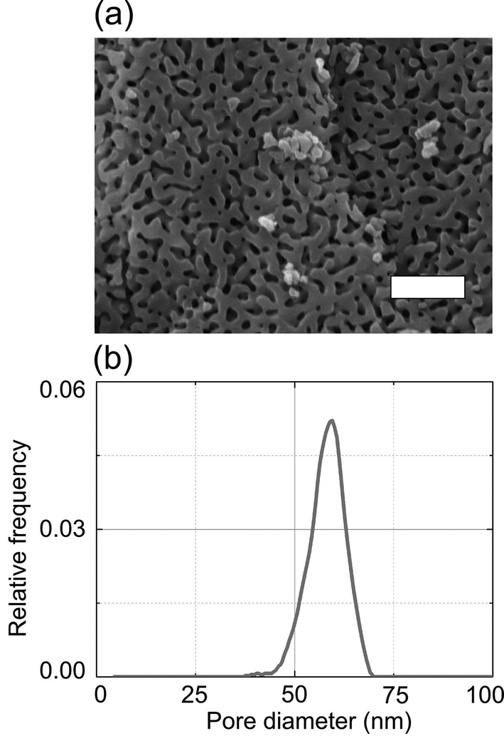 | ||
| Fig. 1 Morphology and pore size distribution of controlled porous glass. (a) Scanning electron microscopy image of a CPG membrane (the scale bar corresponds to 200 nm) and (b) pore diameter distribution of a CPG membrane obtained by mercury intrusion. | ||
2 Experimental section
2.1 Materials
Ethanol (purity 99.8%) and rhodamine 6G (R6G; purity 99%) were obtained from Aldrich. Ethanol was selected as model liquid because it is a common solvent used in non-aqueous syntheses of porous materials24 and for swelling-induced pore generation in block copolymer specimens.7,8 Moreover, a broad range of fluorescent probes readily dissolves in ethanol. As nanoporous model system we used CPGs with an average nanopore diameter of 57 nm (Fig. 1a), a standard deviation of the nanopore diameter of ∼5 nm (Fig. 1b) and a porosity of 50%. The overall thickness of the CPG membranes, which were prepared by spinodal decomposition of alkali borosilicate glasses followed by leaching of the boron-rich phase,1 amounted to 500 μm. The SEM picture of a CPG membrane displayed in Fig. 1a was taken with a Zeiss Auriga Scanning Electron Microscope using in-lense detection at an acceleration voltage of 5.00 kV. Pore size distributions and porosities of the CPG membranes were measured by mercury intrusion using Pascal 140 and 440 devices from Porotec (Thermo Finnigan). The samples were dried at 120 °C for 8 h and degassed for 20 minutes before the measurements.2.2 Confocal laser scanning microscopy (CLSM)
For the acquisition of fluorescence intensity mappings we used an Olympus LSM FV1000 confocal laser scanning microscope equipped with a HeNe laser (excitation wavelength 515 nm) and with a 60× oil immersion objective. A CPG piece was glued on a cover slide that was in turn placed on the objective covered by immersion oil (cf. Fig. 2a). 50 μL of a 20 μM solution of R6G in ethanol were dropped onto the surface of the CPG piece while the CLSM was already scanning. R6G exhibits an absorption maximum at 530 nm and an emission maximum at 552 nm (cf. PhotochemCAD package, version 2.1a).25 The scanned area extended 250 μm (481 pixel) in z direction perpendicular to the CPG membrane/glue/cover slide interface and 52 μm (256 Pixel) in x-direction parallel to the CPG membrane/glue/cover slide interface. To capture fluorescence intensity mappings, the focal volume of the CLSM was displaced along the x direction for every z position starting at the bottom of the image field below the CPG membrane/glue/cover slide interface. The duration of a scan and, therefore, the time resolution was 2 s. Sets of thus-obtained fluorescence intensity mappings were processed using the program ImageJ.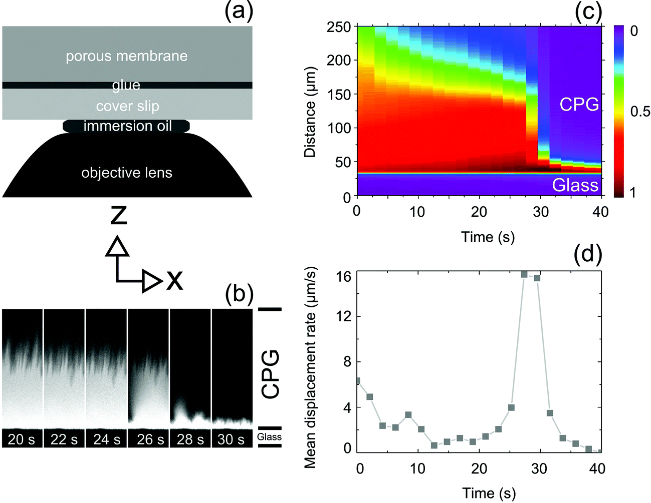 | ||
| Fig. 2 Monitoring the evaporation of ethanol from CPG filled with R6G/ethanol solution by CLSM (coordinate system indicates orientations of the x-direction in panels a, b and of the z-direction in panels a–c). The z-direction is vertically oriented in the paper plane, the x-direction horizontally oriented in the paper plane. The interface CPG membrane/glue/cover slide is oriented parallel to the x-direction. (a) Schematic of the set-up used. (b) Set of two-dimensional fluorescence intensity mappings in the x–z plane extending 250 μm in the z-direction and 52 μm in the x-direction. The interface CPG membrane/glue/cover slide is indicated by the border between the upper bright areas containing R6G/ethanol solution and the dark areas at the bottom (glue and cover slide). (c) Set of vertical one-dimensional pixel arrays oriented along the z-direction (i.e., normal to x-axis and CPG membrane/glue/cover slide interface). Each one-dimensional array of pixels represents a CLSM fluorescence mapping in the x–z plane. The intensity of each pixel represents the value of the integrated fluorescence intensity along the x-direction at the respective z position. The fluorescence intensity mappings represented by panel (c) were successively recorded with a time increment of 2 s and include the fluorescence intensity mappings of panel (b). The interface CPG membrane/glue/cover slide corresponds to the blue line oriented parallel to the x-axis in the bottom part of panel c. (d) Displacement rate of the z position of the air invasion front averaged along the x-direction parallel to the CPG membrane/glue/cover slide interface. The displacement rate was calculated by numerical differentiation of the z-positions of the fluorescence intensity inflection points in the one-dimensional pixel arrays shown in panel (c) with respect to t. | ||
2.3 Thermogravimetric analysis (TGA)
TGA was performed with a Netzsch STA 449C Jupiter device. Pieces of CPG membranes were weighed and then located in aluminum crucibles. 10 μL of pure ethanol were dropped onto the sample surface using an Eppendorf syringe. The sample mass m as function of evaporation time t as well as the heat flow![[Q with combining dot above]](https://www.rsc.org/images/entities/i_char_0051_0307.gif) (t) to the sample were independently acquired at a constant temperature of 25 °C while the samples were purged with a mixture consisting of 20% oxygen and 80% nitrogen at a flow rate of 65 ml min−1. The TGA measurements started about 30 s after ethanol deposition as soon as the covering of the TGA device had closed; m0 corresponded to the sample mass at the start of the TGA measurement. The time resolution of the TGA measurements was 100 ms (10 data points per second), the mass resolution 0.0005 mg, the heat flow resolution 0.00243 mW mg−1 and the enthalpy resolution 0.0005 mJ.
(t) to the sample were independently acquired at a constant temperature of 25 °C while the samples were purged with a mixture consisting of 20% oxygen and 80% nitrogen at a flow rate of 65 ml min−1. The TGA measurements started about 30 s after ethanol deposition as soon as the covering of the TGA device had closed; m0 corresponded to the sample mass at the start of the TGA measurement. The time resolution of the TGA measurements was 100 ms (10 data points per second), the mass resolution 0.0005 mg, the heat flow resolution 0.00243 mW mg−1 and the enthalpy resolution 0.0005 mJ.
3 Results
3.1 Visualization of burst-like mass loss events by CLSM
We monitored the evaporation of ethanol from CPG filled with solutions of the fluorescent dye R6G in ethanol by CLSM to shed light on the spatial propagation of the air invasion front through the spongy CPG nanopore system. If one assumes that R6G molecules are only present in pore volumes filled with the solvent ethanol, the spatial intensity distribution of R6G fluorescence can be considered as representative of the spatial distribution of ethanol. Portions of the scanned area in which the CPG pores are filled with R6G/ethanol solution will thus appear bright, whereas portions of the scanned area in which the CPG pores are empty will appear dark. The experimental design employed for the CLSM experiments is schematically displayed in Fig. 2a. A piece of a CPG membrane was glued on a cover slide that was in turn located on top of an objective lens (the space between objective lens and cover slide was filled with immersion oil). The z-direction is oriented normal to the interface CPG membrane/glue/cover slide. In Fig. 2a–c, the z-direction lies in the paper plane and is vertically oriented. The x-direction is oriented parallel to the interface CPG membrane/glue/cover slide (in Fig. 2a and b horizontally oriented in the paper plane). Series of CLSM scans covering areas extending 250 μm in the z-direction and 52 μm in the x-direction were performed in the x–z-plane oriented perpendicularly to the interface CPG membrane/glue/cover slide with a time resolution of 2 s per scan. In this way, we could repeatedly capture burst-like drainage events emptying membrane volumes with dimensions of the order of the imaged area. A typical burst event is shown in Fig. 2b. The bright areas were filled with R6G/ethanol solution, while no R6G/ethanol solution was present in the dark areas. The sharp interface between the bright areas inside the CPG membrane and the dark areas at the bottom corresponds to the interface CPG membrane/glue/cover slide. While the air invasion front slowly receded in scans taken after 20 s–26 s, a burst-like jump occurred in between the scans taken after 26 s and 28 s; the air invasion front moved by about 100 μm towards the CPG membrane/glue/cover slide interface. After the burst, the R6G molecules were located in an area next to the CPG membrane/glue/cover slide interface with an extension in z-direction of about 10 μm (frames 28 s and 30 s).To visualize complete burst events, each CLSM image representing a fluorescence intensity mapping in the x–z-plane of a sequence of CLSM images capturing a burst event was processed as follows. The fluorescence intensity was integrated along the x-direction parallel to the CPG membrane/glue/cover slide interface for every single z value. Hence, every CLSM image was condensed into a one-dimensional array of pixels oriented parallel to the z-axis and normal to x-axis and CPG membrane/glue/cover slide interface. In these one-dimensional pixel arrays the intensity of an individual pixel represented the value of the fluorescence intensity integrated along the x-direction parallel to the CPG membrane/glue/cover slide interface at the respective z position. Finally, the one-dimensional pixel arrays, each of which represents a CLSM image taken at a specific point of time, were assembled along the time axis. Fig. 2c shows such a set of one-dimensional pixel arrays of fluorescence intensity mappings of a CPG membrane initially saturated with R6G/ethanol solution representing the burst-like jump of the air invasion front also shown in Fig. 2b. In a given one-dimensional pixel array, the integrated fluorescence intensity decreased with increasing distance from the CPG membrane/glue/cover slide interface. The position of the air invasion front averaged along the x-direction for a given fluorescence intensity mapping was indicated by a stepwise decrease in the integrated fluorescence intensity along the one-dimensional pixel arrays, i.e., along the z-direction. We considered the inflection points appearing in these steps as z-positions of the air invasion fronts averaged along the x-direction. Fig. 2d shows the numerically calculated derivative of the average z position of the invasion front with respect to t. In the time period between ∼11 s and ∼23 s, the mean z position of the invasion front moved at a by and large constant apparent displacement rate ranging from ∼1 μm s−1 to ∼2 μm s−1 towards the CPG membrane/glue/cover slide interface. Strikingly, starting at t ∼25 s, the apparent mean z position of the air invasion front jumped within four consecutive fluorescence intensity mappings by more than 80 μm to the CPG membrane/glue/cover slide interface. Taking into account the isotropic nature of the CPG pore system, it is reasonable to assume that the CPG membrane volume affected by a burst-like mass loss event has similar extensions in all space directions. Hence, a CPG membrane volume of at least 106 μm3 was affected by the captured burst-like mass loss event (the CPG membrane volume affected by the burst-like mass loss event may extend beyond the scanned area).
3.2 TGA analysis of burst-like mass loss events
To further elucidate the nature of the burst-like jumps of the air invasion front detected by CLSM, we monitored the evaporation of ethanol from CPG by TGA under isothermal conditions. The mass m and the burst velocity v (mass change dm per time intervall dt) are shown as functions of evaporation time t in Fig. 3a and b. Closer inspection reveals the occurrence of nearly vertical steps in the m(t) profiles (Fig. 3a), which appear as negative spikes in the derivatives dm/dt of the sample mass with respect to evaporation time (Fig. 3b). Strikingly, the burst-like mass loss events were not accompanied by burst-like heat flow events, as apparent from the corresponding(t)/m0 profile (Fig. 3c) and the ![[Q with combining umlaut]](https://www.rsc.org/images/entities/i_char_0051_0308.gif) (t)/m0 profile obtained by differentiating (t)/m0 with respect to t (Fig. 3d). We consider dm/dt as a more realistic measure of the burst velocity v than the displacement rate of the air invasion front derived from the CLSM mappings (Fig. 2d) because the time resolution of the TGA device used here is one order of magnitude better than the time resolution of the CLSM measurements and because the CLSM scans only capture a fraction of the CPG volume affected by a jump of the air invasion front. The evaluation of 298 burst-like mass loss events captured in 10 independent TGA experiments revealed that the frequency density f of v can be fitted by a power law of the type f = a·vb, where the pre-exponential factor a is ∼0.003 (s mg−1)b (Fig. 4a). The scaling exponent b equals ∼−2.6. The largest burst-like mass loss event we captured was associated with a burst velocity of −0.1275 mg s−1. In the course of this burst-like mass loss event, 27 μg liquid ethanol corresponding to a liquid volume of 3.4 × 107 μm3 were converted to gaseous ethanol. The frequency density of time periods between burst-like mass loss events is shown in Fig. 4b. Frequency maximums occur at 2–3 s and at around 20 s.
(t)/m0 profile obtained by differentiating (t)/m0 with respect to t (Fig. 3d). We consider dm/dt as a more realistic measure of the burst velocity v than the displacement rate of the air invasion front derived from the CLSM mappings (Fig. 2d) because the time resolution of the TGA device used here is one order of magnitude better than the time resolution of the CLSM measurements and because the CLSM scans only capture a fraction of the CPG volume affected by a jump of the air invasion front. The evaluation of 298 burst-like mass loss events captured in 10 independent TGA experiments revealed that the frequency density f of v can be fitted by a power law of the type f = a·vb, where the pre-exponential factor a is ∼0.003 (s mg−1)b (Fig. 4a). The scaling exponent b equals ∼−2.6. The largest burst-like mass loss event we captured was associated with a burst velocity of −0.1275 mg s−1. In the course of this burst-like mass loss event, 27 μg liquid ethanol corresponding to a liquid volume of 3.4 × 107 μm3 were converted to gaseous ethanol. The frequency density of time periods between burst-like mass loss events is shown in Fig. 4b. Frequency maximums occur at 2–3 s and at around 20 s.
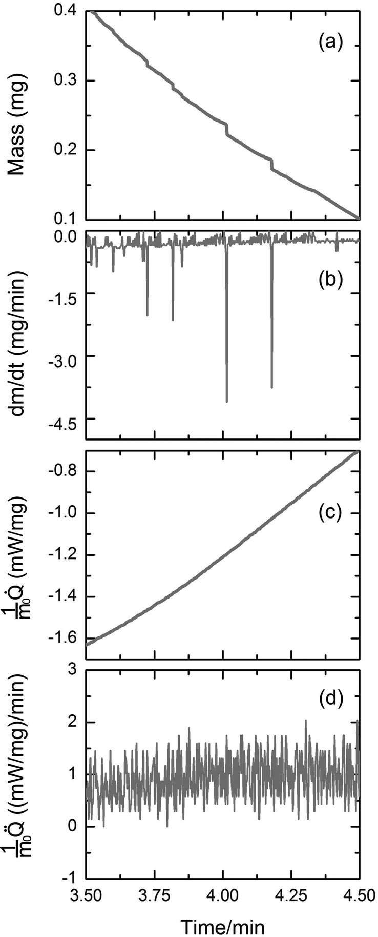 | ||
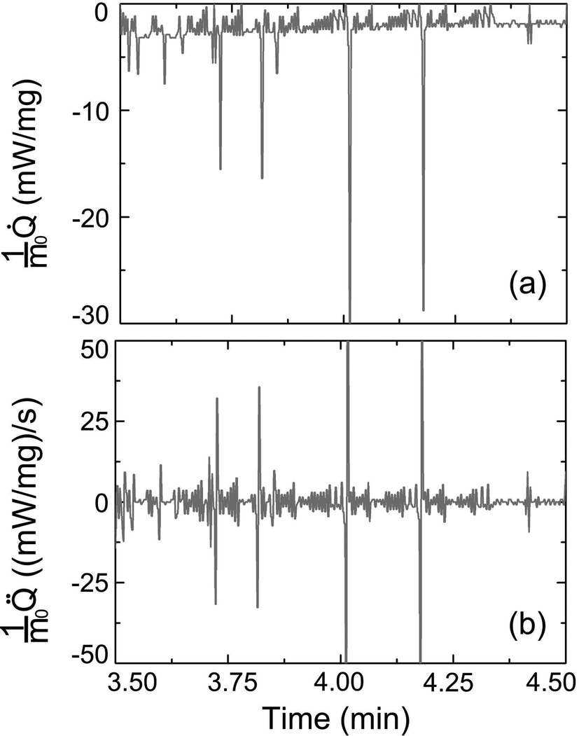
| Fig. 3 TGA analysis of burst-like mass loss events during evaporation of ethanol from CPG. (a) Sample mass m as function of evaporation time t. The constant sample mass after complete evaporation of ethanol was set to 0.00 mg. (b) Loss of sample mass dm per time interval dt as function of t calculated by numerical differentiation of the m(t) profile of panel (a). (c) Heat flow /m0 as function of t and (d) change in heat flow (t)/m0 calculated by differentiating the (t)/m0 profile of panel (c) with respect to t. | ||
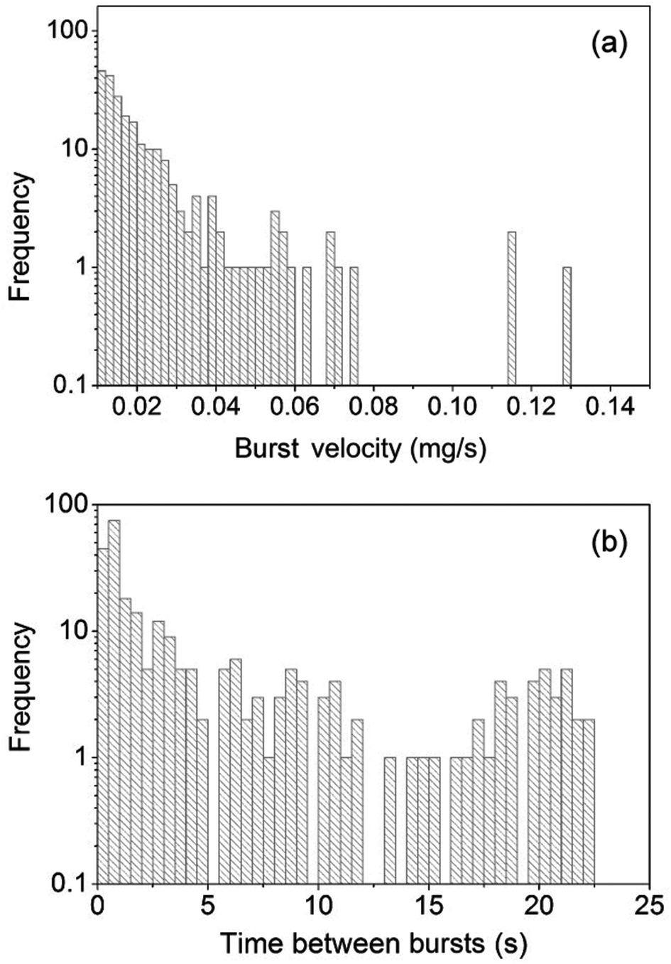 | ||
| Fig. 4 Statistical evaluation of adiabatic evaporation bursts captured in 10 independent TGA experiments. The cut-off size to separate adiabatic evaporation bursts from noise was set to −0.01 mg s−1. (a) Frequency density of the velocities dm/dt (mass loss per time interval) of overall 298 adiabatic evaporation bursts. (b) Frequency density of time intervals between burst-like mass loss events during evaporation of ethanol from CPG. Overall 297 time intervals were considered. | ||
3.3 Enthalpy of evaporation
During isothermal TGA measurements, m(t) and(t)/m0 profiles are independently acquired. In the course of an isothermal but non-isochoric evaporation experiment the heat transferred to the evaporating system corresponds to the actual enthalpy of vaporization. Thus, we compared the (t)/m0 profile directly measured between evaporation times 3.50 and 4.50 minutes (Fig. 3c) with the (t)/m0 profile calculated from the m(t) trace between evaporation times 3.50 and 4.50 minutes (Fig. 3a) using the molar enthalpy of vaporization of ethanol (42.32 kJ mol−1 at 25 °C26). Fig. 5a displays the (t)/m0 profile calculated from the m(t) trace shown in Fig. 3a, whereas Fig. 5b shows the (t)/m0 profile obtained by differentiating the (t)/m0 profile of Fig. 5a with respect to evaporation time t. If evaporation of ethanol from CPG had been entirely endothermic, the burst-like sample mass losses apparent in the m(t) trace shown in Fig. 3a would have been accompanied by pronounced spikes in the (t)/m0 profiles, as obvious from Fig. 5a. Strikingly, these spikes are absent in the experimentally acquired (t)/m0 profile seen in Fig. 3c. Hence, the burst-like mass loss events apparent in Fig. 3a and b must be adiabatic since they were not accompanied by spikes in the heat flow. The absolute enthalpy of vaporization expected for evaporation exclusively occurring in the classical endothermic evaporation mode between t = 3.50 minutes and t = 4.50 minutes amounted to 275.6 mJ and was calculated by numeric integration of the (t)/m0 profile seen in Fig. 5a. In striking contrast, numerical integration of the directly measured (t)/m0 profile displayed in Fig. 3c between t = 3.50 minutes and t = 4.50 minutes yielded an actual evaporation enthalpy of only 143.2 mJ.
 | ||
| Fig. 5 Simulation of purely endothermic evaporation based on the m(t) trace of Fig. 3a. (a) Heat flow normalized to the initial sample mass m0 as function of evaporation time calculated for the experimental m(t) profile displayed in Fig. 3a using the molar enthalpy of vaporization of ethanol at 25 °C. (b) Change in heat flow normalized to m0 calculated by differentiating the (t)/m0 profile of panel (a) with respect to t. | ||
4 Discussion
4.1 Endothermic versus adiabatic evaporation
In the classical endothermic evaporation scenario, the partial pressure of an evaporating species in the gas phase lies below the equilibrium value. Then, preferentially those molecules that carry an above-average amount of energy stored in macroscopically undirected molecular motions move from the liquid phase to the gas phase. As hot molecules deplete in the liquid phase and enrich in the gas phase, the remaining liquid phase looses heat to the gas phase and tries to balance this heat loss by heat uptake from the environment. Under isothermal conditions, any mass transfer from the liquid phase to the gas phase driven by non-equilibrium partial pressure of the evaporating species in the gas phase is inevitably accompanied by heat flow from the environment into the liquid phase. This heat flow must be apparent in(t)/m0 profiles obtained by means of TGA monitoring. The classical model of the drying of gel monoliths in the course of sol–gel syntheses comprising evaporation from a wet surface of a shrinking gel body (stage 1), evaporation coupled with liquid film flow on the pore walls of the stiffened gel body towards its outer surface (stage 2) and finally evaporation coupled with mass transport by gas diffusion of the evaporating liquid through the pores of the gel body (stage 3) exclusively relies on the classical endothermic evaporation mode.2,3
Strikingly, the burst-like mass loss events apparent in Fig. 3a and b are not accompanied by burst-like features in the directly measured (t)/m0 profiles (Fig. 3c) and the (t)/m0 profiles (Fig. 3d). Moreover, the vaporization enthalpy calculated from the mass of evaporated ethanol and the molar enthalpy of vaporization of ethanol was nearly twice as high as the directly measured enthalpy of vaporization determined from the experimental (t)/m0 profiles. Thus, nearly half of the overall amount of vaporized ethanol evaporated via an adiabatic process. Adiabatic conversion of an instable liquid phase into a thermodynamically stable gas phase may occur if the liquid phase has a pressure below the pressure range in which the liquid would be thermodynamically stable. Liquids confined to nanopores indeed reach such low pressures, as shown experimentally27–29 and as revealed by simulations.30 The occurrence of low or even negative liquid pressures during drainage in porous media can be rationalized as follows. The air invasion front consists of menisci that are concave with respect to the receding wetting liquid and convex with respect to the invading non-wetting gaseous fluid. According to the Young–Laplace equation, the pressure in the receding wetting liquid must be lower than the pressure in the invading non-wetting gas phase. The resulting pressure difference across a meniscus is referred to as capillary pressure PC.31PC increases along with the curvature of a meniscus. As menisci in narrow pores are more curved than in wider pores, PC in narrow pores is larger than in wider pores, and the pressure of the receding wetting liquid in narrower pores is lower than in wider pores. These pressure differences in the receding wetting liquid caused by different meniscus curvatures in turn draw the receding wetting liquid from wider pores into narrower pores.32–34 Thus, invasion front configurations as that displayed in Fig. 6a emerge, which are dominated by highly curved menisci located in narrow necks of the pore system. The pronounced curvature of the menisci leads to further increase in PC and further decrease in liquid pressure. Finally, the air invasion front gets unstable and relaxes. The observed burst-like mass loss events can be considered as adiabatic evaporation bursts, which push the system towards equilibrium along an adiabatic but non-isochoric route.
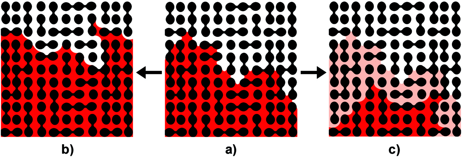 | ||
| Fig. 6 Relaxation mechanisms of an unstable air invasion front (black, porous host; red, evaporating liquid). (a) In the course of drying, the menisci at the air invasion front are drawn in narrow pore segments (pore necks). As a result, the curvatures of the menisci and the capillary pressure PC across their interfaces increase. Eventually, the air invasion front gets unstable. (b) Hydraulic relaxation of the unstable air invasion front by classical Haines jumps involves local liquid flow at the air invasion front so as to realize meniscus configurations characterized by lower meniscus curvatures and lower capillary pressures. However, no mass transport away from the air invasion front takes place. (c) In narrow nanopores, the curvature of the menisci is so pronounced that the liquid in the vicinity of the menisci has a pressure below the pressure range in which the liquid would be stable. Relaxation of the air invasion front thus occurs by adiabatic burst evaporation converting unstable liquid to gas. The conversion front propagates avalanche-like into the liquid-filled volume of the nanoporous host until a new stable air invasion front characterized by low meniscus curvatures and low capillary pressures forms. The beige area indicates the liquid volume converted to gas. As adiabatic burst evaporation is associated with volume expansion, the formed gas is pushed out of the porous host that correspondingly looses the mass of the converted liquid in a burst-like mass loss event. | ||
4.2 Adiabatic evaporation bursts and classical Haines jumps
Evaporation of a volatile liquid from a nanoporous medium corresponds to a drainage scenario. The evaporating wetting liquid initially saturating the nanoporous medium is replaced by an invading gas phase that can be considered as non-wetting fluid. Rapid reconfigurations of invasion fronts during drainage processes reducing PC on time scales typically ranging from 1 ms to 10 ms![[thin space (1/6-em)]](https://www.rsc.org/images/entities/char_2009.gif) 35 are, in principle, well known and often referred to as Haines jumps.13–23 Haines jumps in the course of drainage processes are initiated as soon as the pressure of the invading non-wetting fluid exceeds the breakthrough value at the largest morphological restriction. Then, the configuration of the air invasion front gets unstable. Rapid redistribution of the receding wetting liquid by local liquid flow through hydraulically coupled pores displaces the mensici at the invasion front from narrower pores to wider pores where they have smaller curvatures (Fig. 6b).17,18,23 Thus, PC drops, and the hydraulic redistribution of liquid comes to a halt as soon as a new stable air invasion front configuration has been reached.
35 are, in principle, well known and often referred to as Haines jumps.13–23 Haines jumps in the course of drainage processes are initiated as soon as the pressure of the invading non-wetting fluid exceeds the breakthrough value at the largest morphological restriction. Then, the configuration of the air invasion front gets unstable. Rapid redistribution of the receding wetting liquid by local liquid flow through hydraulically coupled pores displaces the mensici at the invasion front from narrower pores to wider pores where they have smaller curvatures (Fig. 6b).17,18,23 Thus, PC drops, and the hydraulic redistribution of liquid comes to a halt as soon as a new stable air invasion front configuration has been reached.
Haines jumps do not involve burst-like mass transfer of the evaporating species out of the porous medium. One could reason that thin wetting films of the receding liquid remain on the walls of the pores emptied by a Haines jump. It has been stressed that Haines jumps are cooperative phenomena affecting a large number of interconnected pore segments.35 The increased air/liquid interfacial area related to the presence of the above-mentioned thin wetting films could, therefore, be considered as possible origin of enhanced evaporation rates. However, while the thin wetting films would have been generated by a jump-like event, evaporation of thin wetting films as such would not be burst-like. Hence, it is hard to conceive that burst-like mass losses can be generated in this way. More importantly, thin wetting films would evaporate in the classical endothermic mode. The adiabatic character of the burst-like mass loss events can thus not be explained in this way. Therefore, the burst-like mass loss events we observed during evaporation of ethanol from CPG cannot be explained by Haines jumps.
4.3 Initiation of adiabatic burst evaporation events
The question arises as to how adiabatic burst evaporation events in a porous medium are initiated. Adiabatic evaporation bursts are evidently discrete events. Hence, a mechanism must exist that initiates adiabatic evaporation bursts. A common mechanism for the formation of gas bubbles within liquids is cavitation, which is initiated by homogeneous or heterogeneous nucleation. In the specific case of liquids confined to porous media, cavitation was suggested as potential drainage mechanism36 and as mechanism contributing to the drying of gel bodies in the course of sol–gel-syntheses.37 However, it is reasonable to assume that adiabatic evaporation bursts are not initiated by classical nucleation of a gas phase within a liquid phase. Cavitation initiated by classical nucleation within a liquid phase confined to pores is typically associated with meniscus pinning.38 Therefore, nucleation of gas bubbles within a liquid should result in the formation of gaseous domains encapsulated by liquid accompanied by pinning of the menisci at the air invasion front. As obvious from the representative CLSM results shown in Fig. 2b and c, no indications of meniscus pinning were detectable in our experiments. Instead, CLSM monitoring indicated that adiabatic evaporation bursts start at air invasion fronts and propagate away from the initial positions of the air invasion fronts into initially liquid-filled regions of porous media, as schematically displayed in Fig. 6c. At air invasion fronts menisci that topologically correspond to half bubbles are abundant. Heterogeneous nucleation39 on external surfaces reduces the free energy barrier that needs to be overcome to form stable nuclei of a thermodynamically stable phase out of a metastable phase as compared to homogeneous nucleation.40 Analogous to external surfaces initiating heterogeneous nucleation, the meniscus interfaces at the air invasion front may facilitate initiation of adiabatic evaporation bursts. However, as meniscus interfaces are permanently present, an additional trigger mechanism for adiabatic evaporation bursts must exist.The bimodal frequency density of time intervals between burst-like mass loss events with two distinct maximums (Fig. 4b) indicates that initiation of adiabatic burst evaporation events is coupled to another process that determines the durations of these time intervals. This second phenomenon could be the built-up of capillary pressure large enough to destabilize the meniscus configuration at the air invasion front. Menisci at air invasion fronts of microporous and mesoporous media as well as of media with small macropores just above the mesoscopic size range are strongly curved. Thus, the corresponding capillary pressures are high and the liquid pressures close to the menisci are so low that the liquid may be metastable. Under these conditions, jump-like relaxations of air invasion fronts will occur by adiabatic burst evaporation rather than by Haines jumps. Adiabatic burst evaporation events are coupled with avalanche-like propagation of the air invasion fronts; displacement of the air invasion fronts takes place by vaporization of the metastable liquid and not by local liquid flow as in the case of Haines jumps (Fig. 6c). The rapid adiabatic conversion of receding wetting liquid to gas is a non-isochoric process associated with significant volume expansion. The formed gas is pushed out of the nanoporous medium and the mass of the liquid phase located in the nanoporous medium drops jump-like. Hence, Haines jumps and adiabatic burst evaporation are competing mechanisms for the reconfiguration of unstable air invasion fronts, and it is straightforward to assume that in nanoporous media adiabatic evaporation bursts prevail. Moreover, we believe that the stopping criterion for adiabatic burst evaporation events is the same as that for Haines jumps. Thus, an adiabatic burst evaporation event comes to a halt as soon as capillary pressures are small enough and liquid pressures are high enough to stabilize a new configuration of the air invasion front.
5 Conclusions
Using ethanol as evaporating model liquid and controlled porous glass as nanoporous model matrix, we have shown that adiabatic burst evaporation significantly contributes to the evaporation of volatile liquids from nanoporous media with nanopore diameters of a few 10 nm and sponge-like bicontinuous morphology. The comparison of experimentally measured vaporization enthalpies and vaporization enthalpies expected for exclusively endothermic evaporation calculated from liquid mass loss revealed that nearly half of the liquid evaporated adiabatically. Adiabatic burst evaporation is accompanied by burst-like mass loss events during which liquid volumes of up to 107 μm3 are converted to gas. Adiabatic burst evaporation occurs because liquid in the vicinity of strongly curved menisci inside nanopores has low liquid pressures and is, therefore, metastable. Burst-like conversion of metastable liquid to gas is triggered by unstable meniscus configurations at air invasion fronts caused by the build-up of high capillary pressures. Adiabatic evaporation bursts propagate avalanche-like through sponge-like nanopore systems until a new stable configuration of the air invasion is reached. Our results indicate that in nanoporous media adiabatic evaporation bursts prevail over Haines jumps, another mechanism for the relaxation of unstable air invasion fronts that involves reconfiguration of the menisci at the liquid-air interface by local liquid flow without mass transfer away from the air invasion front. These insights may improve the understanding of drying processes in bottom-up syntheses of nanoporous materials based on sol–gel chemistry or spinodal decomposition in solution, of solution impregnation of porous media with functional materials and of desorption processes in nanoporous media.Acknowledgements
Technical support by the Center of Advanced Light Microscopy Osnabrück and R. Kurre as well as funding by the European Research Council (ERC-CoG-2014; project 646742 INCANA) is gratefully acknowledged. L. X. thanks the Alexander von Humboldt Foundation for a fellowship.References
- D. Enke, F. Janowski and W. Schwieger, Microporous Mesoporous Mater., 2003, 60, 19–30 CrossRef CAS.
- L. L. Hench and J. K. West, Chem. Rev., 1990, 90, 33–72 CrossRef CAS.
- L. L. Hench and M. J. R. Wilson, J. Non-Cryst. Solids, 1990, 121, 234–243 CrossRef CAS.
- C. J. Brinker and G. W. Scherer, Sol-gel Science: The Physics and Chemistry of Sol-gel Processing, Gulf Professional Publishing, 1990, pp. 471–474 Search PubMed.
- A. Sarkar, S. R. Chaudhuri, S. Wang, F. Kirkbir and H. Murata, J. Sol-Gel Sci. Technol., 1994, 2, 865–870 CrossRef CAS.
- P. van de Witte, P. J. Dijkstra, J. W. A. van den Berg and J. Feijen, J. Membr. Sci., 1996, 117, 1–31 CrossRef CAS.
- Y. Wang, C. He, W. Xing, F. Li, L. Tong, Z. Chen, X. Liao and M. Steinhart, Adv. Mater., 2010, 22, 2068–2072 CrossRef CAS PubMed.
- Y. Wang and F. Li, Adv. Mater., 2011, 23, 2134–2148 CrossRef CAS PubMed.
- Q. Jiang and M. D. Ward, Chem. Soc. Rev., 2014, 43, 2066–2079 RSC.
- P. I. Ravikovitch and A. V. Neimark, Langmuir, 2002, 18, 9830–9837 CrossRef CAS.
- M. Thommes, B. Smarsly, M. Groenewolt, P. I. Ravikovitch and A. V. Neimark, Langmuir, 2006, 22, 756–764 CrossRef CAS PubMed.
- C. Reichenbach, G. Kalies, D. Enke and D. Klank, Langmuir, 2011, 27, 10699–10704 CrossRef CAS PubMed.
- W. B. Haines, J. Agric. Sci., 1930, 20, 97–116 CrossRef CAS.
- N. R. Morrow, Ind. Eng. Chem., 1970, 62, 32–56 CrossRef CAS.
- T. M. Shaw, Phys. Rev. Lett., 1987, 59, 1671–1674 CrossRef CAS.
- S. Roux and E. Guyon, J. Phys. A: Math. Gen., 1989, 22, 3693–3705 CrossRef.
- K. J. Maloy, L. Furuberg, J. Feder and T. Jossang, Phys. Rev. Lett., 1992, 68, 2161–2164 CrossRef.
- L. Furuberg, K. J. Maloy and J. Feder, Phys. Rev. E: Stat. Phys., Plasmas, Fluids, Relat. Interdiscip. Top., 1996, 53, 966–977 CrossRef CAS.
- E. Aker, K. J. Maloy, A. Hansen and S. Basak, Europhys. Lett., 2000, 51, 55–61 CrossRef CAS.
- D. Crandall, G. Ahmadi, M. Ferer and D. H. Smith, Physica A, 2009, 388, 574–584 CrossRef PubMed.
- F. Moebius and D. Or, J. Colloid Interface Sci., 2012, 377, 406–415 CrossRef CAS PubMed.
- S. Berg, H. Ott, S. A. Klapp, A. Schwing, R. Neiteler, N. Brussee, A. Makurat, L. Leu, F. Enzmann, J.-O. Schwarz, M. Kersten, S. Irvine and M. Stampanoni, Proc. Natl. Acad. Sci. U. S. A., 2013, 110, 3755–3759 CrossRef CAS PubMed.
- R. T. Armstrong and S. Berg, Phys. Rev. E: Stat. Phys., Plasmas, Fluids, Relat. Interdiscip. Top., 2013, 88, 043010 CrossRef.
- J. Joo, S. G. Kwon, T. Yu, M. Cho, J. Lee, J. Yoon and T. Hyeon, J. Phys. Chem. B, 2005, 109, 15297–15302 CrossRef CAS PubMed.
- J. M. Dixon, M. Taniguchi and J. S. Lindsey, Photochem. Photobiol., 2005, 81, 212–213 CrossRef CAS.
- CRC Handbook of Chemistry and Physics, 87th Edition, ed. D. R. Lide, CRC Press, 2006, pp. 6–99 Search PubMed.
- N. R. Tas, P. Mela, T. Kramer, J. W. Berenschot and A. van den Berg, Nano Lett., 2003, 3, 1537–1540 CrossRef CAS.
- T. D. Wheeler and A. D. Stroock, Nature, 2008, 455, 208–212 CrossRef CAS PubMed.
- O. Vincent, P. Marmottant, P. A. Quinto-Su and C.-D. Ohl, Phys. Rev. Lett., 2012, 108, 184502 CrossRef.
- R. Zhang, Y. Ikoma and T. Motooka, Nanotechnology, 2010, 21, 105706 CrossRef PubMed.
- H.-J. Butt, K. Graf and M. Kappl, in Liquid Surfaces, Wiley-VCH, 2004, pp. 4–25 Search PubMed.
- L. Xu, S. Davies, A. B. Schofield and D. A. Weitz, Phys. Rev. Lett., 2008, 101, 094502 CrossRef.
- N. Shokri, P. Lehmann and D. Or, Phys. Rev. E: Stat. Phys., Plasmas, Fluids, Relat. Interdiscip. Top., 2010, 81, 046308 CrossRef CAS.
- N. Shokri and M. Sahimi, Phys. Rev. E: Stat. Phys., Plasmas, Fluids, Relat. Interdiscip. Top., 2012, 85, 066312 CrossRef.
- S. Berg, R. Armstrong, H. Ott, A. Georgiadis, S. A. Klapp, A. Schwing, R. Neiteler, N. Brussee, A. Makurat, L. Leu, F. Enzmann, J. O. Schwarz, M. Wolf, F. Khan, M. Kersten, S. Irvine and M. Stampanoni, Petrophysics, 2014, 55, 304–312 Search PubMed.
- D. Or and M. Tuller, Water Resour. Res., 2002, 38, 19 CrossRef.
- G. W. Scherer and D. M. Smith, J. Non-Cryst. Solids, 1995, 189, 197–211 CrossRef CAS.
- C. Duan, R. Karnik, M.-C. Lu and A. Majumdar, Proc. Natl. Acad. Sci. U. S. A., 2012, 109, 3688–3693 CrossRef CAS PubMed.
- D. Turnbull, J. Chem. Phys., 1950, 18, 198–203 CrossRef CAS PubMed.
- D. W. Oxtoby, J. Phys.: Condens. Matter, 1992, 4, 7627–7650 CrossRef.
| This journal is © The Royal Society of Chemistry 2015 |