
Redox properties of nanostructured lanthanide-doped ceria spheres prepared by microwave assisted hydrothermal homogeneous co-precipitation†
F. F.
Muñoz
a,
L. M.
Acuña
ab,
C. A.
Albornoz
c,
A. G.
Leyva
cd,
R. T.
Baker
e and
R. O.
Fuentes
*bc
aCINSO (Centro de Investigaciones en Sólidos), CONICET-CITEDEF, J.B. de La Salle 4397, 1603 Villa Martelli, Buenos Aires, Argentina
bCONICET, Buenos Aires, Argentina. E-mail: rofuentes@conicet.gov.ar
cDepartamento de Física, Centro Atómico Constituyentes, CNEA, Av. Gral. Paz 1499, (1650) San Martín, Buenos Aires, Argentina
dEscuela de Ciencia y Tecnología, Universidad Nacional de San Martín, Av. Gral. Paz 1499, (1650) San Martín, Buenos Aires, Argentina
eEaStChem, School of Chemistry, University of St. Andrews, North Haugh, St. Andrews, Fife, KY16 9ST, UK
First published on 30th October 2014
Abstract
In this work, nanostructured LnxCe1−xO2−δ (Ln: Gd and Pr; x = 0.1 and 0.2) spheres were synthesized by microwave assisted hydrothermal homogeneous co-precipitation and their properties were characterized by synchrotron radiation XRD, X-ray absorption near-edge spectroscopy (XANES) and scanning and high-resolution electron microscopy (SEM and HRTEM). In situ XRD and XANES experiments were carried out under reducing and oxidizing conditions in order to investigate the redox behaviour of these materials. The nanostructured mixed oxide spheres were found to have a cubic crystal structure (Fm3m space group). The spheres were composed of nanoparticles with an average crystallite size of about 10 nm. The Ln0.1Ce0.9O2−δ compositions exhibited the highest specific surface area (∼60 m2 g−1). In situ XRD experiments showed an increase in lattice parameters upon reduction, which was attributed to the reduction of Ce4+ and Pr4+ cations to Ce3+ and Pr3+, which have larger radii, and to the associated increase in VO concentration. This increase in lattice parameters was considerably more pronounced for PrDC than GDC, and was explained by the considerably larger change in ionic radius for Pr upon reduction. XANES absorption experiments at the Ce and Pr L3-edge showed that the changes observed upon reduction of the Pr-containing samples resulted mostly from the formation of Pr3+ rather than Ce3+, and supported the previously reported proposal that Pr3+ has a stabilizing effect on Ce4+.
Introduction
Materials based on ceria are widely used for a variety of catalytic applications such as three-way catalysts,1 solid oxide fuel cells2,3 and supports for the water-gas-shift reaction.4,5 Many of these applications rely on the high oxygen ion conductivity and oxygen storage capacity, which can easily be achieved in ceria by doping with other aliovalent cations such as rare earth elements (e.g. Gd, Pr, Sm, Tb). This creates oxygen vacancies, which enable the migration of oxygen ions through the lattice.6 Oxygen ion vacancies (VO˙˙) are responsible for the ionic conductivity of the doped ceria.7,8 Because they exhibit high ionic conductivity at moderate temperatures (above 600 °C), these materials are considered promising for application in electrolytes for intermediate temperature solid oxide fuel cells (IT-SOFCs).9,10 However, oxygen ion vacancies can also be created by interaction of ceria with the gas-phase. Under reducing atmosphere, both electronic (Ce′Ce) and ionic (VO˙˙) charge carriers can be created through loss of oxygen ions from the lattice as molecular oxygen. The presence of both ionic and electronic charge carriers gives rise to a mixed (ionic and electronic) conducting behaviour in both undoped and doped cerias (e.g. Lanthanide-doped ceria, LnDCs) in reducing conditions. This is a difficulty for the application of LnDCs in SOFC electrolytes, where electronic conductivity would give rise to an internal short circuit of the electrolyte, but would be an advantage for the use of these doped cerias in anodes for IT-SOFCs. The increasingly wide use of such materials as catalyst components has prompted a renewed interest in their preparation in the form of nanostructured materials with controlled morphologies and high surface areas.11 Moreover, it is well known that the specific preparation method and morphology of catalysts and other nanomaterials have a strong influence on their physicochemical properties.Ceria doped with a univalent cation, for example, gadolinia-doped ceria, shows n-type electronic conductivity due to the partial reduction of Ce4+ to Ce3+ at high temperatures (>600 °C) under reducing conditions.12 However, ceria doped with a multivalent cation (e.g. M3+/M4+) can exhibit mixed (n-type and oxygen ion) conduction at higher oxygen partial pressures, because of the stability of the lower oxidation state of the dopant ion (M3+). This enables the application of these materials in oxygen separation membranes.13,14 It has been reported that the presence of multivalent praseodymium (Pr3+,4+) in Pr doped ceria enhanced the formation and migration of oxygen vacancies and that, upon reduction of the oxide, creating oxygen ion vacancies, the formation of Pr3+ was favored over the formation of Ce3+.15,16
Different techniques can be used to study the physicochemical properties of nanostructured ceria and doped ceria materials, such as X-ray photoelectron spectroscopy (XPS) and Positron annihilation lifetime spectroscopy (PALS), which are well established techniques to study the electronic configuration and defects in materials, respectively.17,18 Borchert et al. reported on the surface properties of nanostructured cerium dioxide samples doped with praseodymium and prepared by the Pechini method.17 They found that cerium was mainly in the +4 oxidation state, whereas about one-half of the praseodymium ions were found to be in the +3 state. In this case, the oxidation states of Ce and Pr ions were determined by XPS. However, there is a danger that this method would have overestimated the Ce3+ concentration because XPS is performed under high-vacuum (10−9 Torr) and this is likely to cause the reduction of additional Ce4+ to Ce3+ during the XPS measurements,19 that is, if the oxidation state of cerium on ceria surfaces responded dynamically upon exposure to high vacuum (and X-ray irradiation), as would be expected, some of these studies may have inferred surface redox states that are not representative of ceria in ambient or in a catalytic reaction environment. X-ray absorption near edge spectroscopy (XANES), however, is a technique that can circumvent this limitation because it can be employed in vacuum, under ambient pressure (as in the work presented here), or under high pressure. For this reason, XANES seems to be a more appropriate technique to study redox properties under operating conditions, particularly for materials with a high content of reducible ions such as Ce.
In the present work, we report the redox properties of ceria materials doped with univalent (Gd3+) and multivalent (Pr3+,4+) cations and possessing a controlled morphology. Nanostructured Gd0.1Ce0.9O1.95, Gd0.2Ce0.8O1.9, Pr0.1Ce0.9O2−δ and Pr0.2Ce0.8O2−δ spheres were synthesized by a microwave-assisted hydrothermal homogeneous co-precipitation technique. The resulting nanostructured spheres were characterized by synchrotron radiation X-ray diffraction (SR-XRD), X-ray absorption near-edge spectroscopy (XANES), scanning and high-resolution transmission electron microscopy (SEM and HRTEM) and energy dispersive X-ray spectroscopy (EDS). The redox properties of the materials were studied using in situ XANES and XRD experiments carried out under reducing and oxidizing atmospheres at temperatures up to 500 °C.
Experimental
Ce(NO3)3·6H2O (99.99%, Alfa Aesar), Gd(NO3)3·6H2O (99.9%, Alfa Aesar) and Pr(NO3)3·6H2O (99.9%, Alfa Aesar) were employed as precursors. Each nitrate was dissolved in pure deionized H2O separately and then the solutions were mixed to obtain a 0.1 M nitrate solution with molar ratios of Ce![[thin space (1/6-em)]](https://www.rsc.org/images/entities/char_2009.gif) :Gd and Ce:Pr appropriate for the preparation of Gd0.1Ce0.9O1.95 (GDC10), Gd0.2Ce0.8O1.90 (GDC20), Pr0.1Ce0.9O2−δ (PrDC10) and Pr0.2Ce0.8O2−δ (PrDC20). Urea was added in a urea:final oxide molar ratio of 4:1 and 60 ml of the resulting solution was placed in a Teflon-lined autoclave. A Milestone ETHOS 1 Advanced Microwave Digestion system was employed. The sealed autoclave was placed in the oven and was heated to 120 °C with a ramp rate of 30 °C min−1, with the oven power set to 550 W, and then maintained at this temperature for 1 h. After cooling, the white powder produced was collected by centrifugation (2.5 min at 7830 rpm) and dried at 37 °C. After calcination at 500 °C in air for 1 h, the nanostructured LnDC spheres were obtained. Unless otherwise stated, these are the samples studied in what follows. Fig. 1 presents the flow diagram of the microwave assisted hydrothermal homogeneous co-precipitation method employed in this work.
:Gd and Ce:Pr appropriate for the preparation of Gd0.1Ce0.9O1.95 (GDC10), Gd0.2Ce0.8O1.90 (GDC20), Pr0.1Ce0.9O2−δ (PrDC10) and Pr0.2Ce0.8O2−δ (PrDC20). Urea was added in a urea:final oxide molar ratio of 4:1 and 60 ml of the resulting solution was placed in a Teflon-lined autoclave. A Milestone ETHOS 1 Advanced Microwave Digestion system was employed. The sealed autoclave was placed in the oven and was heated to 120 °C with a ramp rate of 30 °C min−1, with the oven power set to 550 W, and then maintained at this temperature for 1 h. After cooling, the white powder produced was collected by centrifugation (2.5 min at 7830 rpm) and dried at 37 °C. After calcination at 500 °C in air for 1 h, the nanostructured LnDC spheres were obtained. Unless otherwise stated, these are the samples studied in what follows. Fig. 1 presents the flow diagram of the microwave assisted hydrothermal homogeneous co-precipitation method employed in this work.
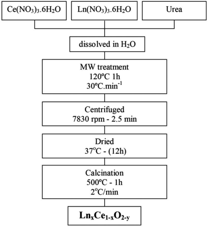 | ||
| Fig. 1 Flowchart illustrating the microwave assisted hydrothermal homogeneous co-precipitation technique used to obtain nanocrystalline GDC and PrDC spheres. | ||
In order to verify the phase composition, conventional X-ray diffraction (XRD) was performed in a PANalytical Empyrean 2 with a PIXel3D detector employing Cu-Kα radiation (1.5418 Å). Data in the angular region 2θ = 20°–90° were collected in a step-scanning mode, with a step length of 0.04° and a step-counting time of 4 s. The average crystallite size, DXRD, of the products was determined using the Scherrer formula20 from the extent of peak broadening of the main XRD reflection (111). Errors in crystallite size were derived by estimating the error in the FWHM (full-width at half-maximum) to be equal to the 2θ step.
Nitrogen adsorption–desorption isotherms were obtained using an Autosorb-1 instrument from Quantachrome. Outgassing was carried out at 200 °C for 16 h prior to the measurements. Analysis of the isotherms using the BET method provided values of the specific surface area (SSA) of the samples.
SEM images were obtained in secondary electron mode using a JEOL 6700F instrument with field emission gun (FEG). A JEOL JSM 5600 instrument equipped with EDS was used for the preparation of EDS spectra. Values of accelerating voltage (in kV) and working distance (WD) are provided in the images. Samples for SEM examination were gold-coated. The image analysis software, Scion Image, was used to obtain particle size information from the SEM images.
TEM images were obtained using a JEOL JEM 2011 instrument operating with a LaB6 filament at an accelerating voltage of 200 kV and equipped with an Oxford Instruments EDS unit. The images were captured using a Gatan CCD camera and analyzed using Digital Micrograph 3.4.4 software. The TEM instrument was also used to obtain EDS spectra and to record two-dimensional elemental distribution maps. For TEM examination, the samples were suspended in acetone and deposited onto holey carbon-coated Cu grids.
XRD patterns were recorded at high temperatures (HT) and in controlled atmospheres using synchrotron radiation at the D10B-XPD beamline of the National Synchrotron Light Laboratory (LNLS, Campinas, Brazil). In these in situ XRD experiments, the sample was mounted on a ceramic sample-holder and placed in a furnace. The X-ray wavelength was set at 1.54892 Å. Data in the angular region 2θ = 20°–100° were collected in a step-scanning mode, with a step length of 0.04° and a step-counting time of 2 s. The data were collected at temperatures ranging from room temperature to 500 °C. The sample was heated at a rate of 10 °C min−1, and a soak time of 10 min was employed at each temperature step before the XRD scan. The thermal and redox behavior of the materials was studied in 5% H2/He (total flow: 20 ml min−1) and in dry synthetic air (total flow: 50 ml min−1). NIST SRM 640c Si powder was used as standard for the instrumental broadening correction.
In situ XANES experiments under conditions of controlled temperature and atmosphere were carried out at the D04B-XAFS1 beamline at LNLS in transmission mode using a Si(111) monochromator for the Ce L3-edge and Pr L3-edge. The nominal photon flux of the beamline was 3 × 10⁹ photons per (s mrad 0.100 mA)@6 keV. All spectra were collected at room temperature for energies in the range 5690–6100 eV with E/ΔE = 5000 to 10000. The energy was calibrated using a Cr foil. Several acquisitions (around 4 spectra) were made on the same sample to improve the signal to noise ratio. Samples were diluted with boron nitride and these mixtures were pressed into 15 mm diameter pellets (around 6 mg of sample and 70 mg of diluent were used). For the transmission measurements, the pellets were placed in a tubular quartz furnace (diameter, 20 mm; X-ray path length, 440 mm) sealed with refrigerated Kapton windows. The temperature was measured and controlled by a thermocouple passed down the sample holder and positioned close to the surface of the pellet. Temperature-resolved XANES spectra at the Ce L3-edge and Pr L3-edge were acquired during temperature-programmed reduction (TPR) under 5% H2/He (total flow: 20 ml min−1) at temperatures from 25 to 500 °C at a heating rate of 10 °C min−1 and with a total data acquisition time of 8 min per spectrum. After the data were collected at 500 °C under 5% H2/He, the system was purged with N2 (100 ml min−1) and synthetic air (21% O2/N2; total flow: 50 ml min−1) was passed through the furnace. After 10 min, data were collected under these oxidizing conditions. The data were normalized using the program WinXAS.21
Results and discussion
Conventional X-ray diffraction (XRD) patterns of the as-synthesized samples obtained by Microwave (MW) treatment (heating at 120 °C for 1 h) and the products after calcining at 250 °C for 1 h and 500 °C for 1 h are shown in Fig. 2(a) and (b) for GDC10 and PrDC10, respectively. At 250 °C, all of the characteristic peaks expected for GDC10 and PrDC10 were already observed (blue lines in Fig. 2(a) and (b)). However, these peaks are relatively broad, indicating that the average crystallite size was very small (about 4–5 nm). At 500 °C (red lines in Fig. 2(a) and (b)), the extent of peak broadening decreased. Even so, the crystallite sizes estimated from the peak widths were still very small (10 nm). A similar behavior was found for GDC20 and PrDC20, but the average crystallite sizes were slightly lower (8 nm).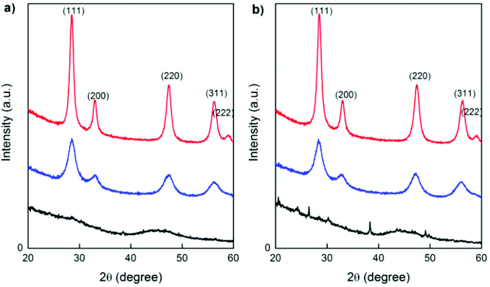 | ||
| Fig. 2 XRD patterns of (a) GDC10 and (b) PrDC10 as-synthesized (obtained by MW treatment; black line) and after calcination for 1 h at 250 °C (blue line) and at 500 °C (red line). | ||
In Table 1, the average crystallite size (DXRD), specific surface area (SSA) and the primary particle size (dBET), calculated from the BET data, are summarized for all samples after calcination at 500 °C. GDC10 and PrDC10 showed larger values of SSA (57.2 m2 g−1 and 60.2 m2 g−1, respectively). The dBET/DXRD ratio was similar for both samples (about 1.6), indicating that the crystallites exhibited a low degree of agglomeration. The values of SSA for both the GDC20 and the PrDC20 samples were considerably lower (13.2 m2 g−1 and 20.7 m2 g−1, respectively) and these samples exhibited a high degree of agglomeration.
| Sample | D XRD/nm | SSA/m2 g−1 | d BET/nm | d BET/DXRD |
|---|---|---|---|---|
| GDC10 | 10.4 | 57.2 | 16.8 | 1.6 |
| GDC20 | 7.8 | 13.2 | 73.0 | 9.4 |
| PrDC10 | 9.8 | 60.2 | 14.2 | 1.6 |
| PrDC20 | 7.5 | 20.7 | 46.5 | 6.2 |
SEM and TEM studies
SEM images recorded at a range of magnifications are presented in Fig. 3 for all four sample compositions. These images clearly show that the preparation method used gave rise to spherical particles of approximately uniform dimensions in all cases. In addition, the yield of the spherical particles was very high, there being very little material present which was extraneous to these structures. The average diameters of the spherical particles were measured from the higher magnification images for each composition and these data are presented in Table 2.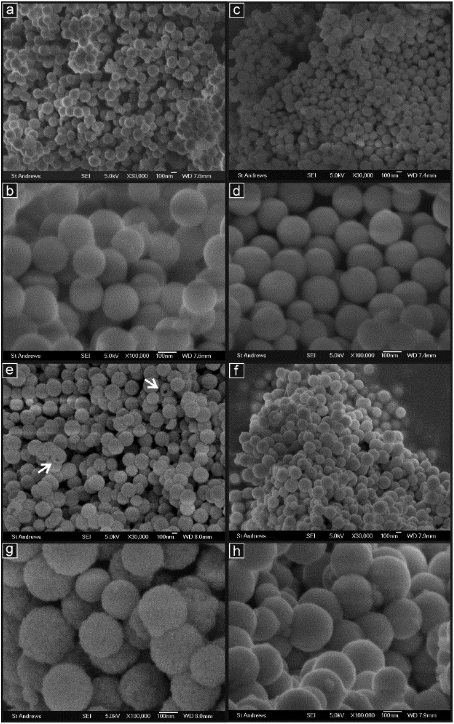 | ||
| Fig. 3 SEM images at intermediate and high magnifications of the samples: (a, b) GDC10; (c, d) PrDC10; (e, g) GDC20; (f, h) PrDC20. Arrows indicate spheres with visible pores. | ||
:Ce) of dopant (X = Gd or Pr) to Ce calculated from EDS spectra obtained by SEM and TEM with target values, and average sphere diameters (ds) for the nanostructured Gd- and Pr-containing spheres. Values are given ± one standard deviation
| Sample | Ln:Ce |
d s/nm | ||
|---|---|---|---|---|
| Target | SEM | TEM | ||
| GDC10 | 0.111 | 0.149 ± 0.0054 | 0.203 | 197 ± 20 |
| PrDC10 | 0.111 | 0.0839 ± 0.0053 | 0.0894 | 187 ± 21 |
| GDC20 | 0.250 | 0.231 ± 0.016 | 0.321 | 255 ± 37 |
| PrDC20 | 0.250 | 0.208 ± 0.012 | 0.244 | 223 ± 41 |
Average diameters were all found to be around 200 nm but the spheres with 20% doping were generally larger than those with 10% doping for both Gd (by 30%) and Pr (by 20%) substitution. In addition, for each dopant level, the Gd-containing samples had slightly larger spheres than those containing Pr (5% larger for 10% doping and 9% larger for 20% doping).
The arrows in Fig. 3(e) indicate two spherical particles of GDC20, which appear to have large pores or cavities. This is discussed further below with reference to the TEM images. The molar ratios of dopant to Ce (Ln:Ce, where X = Gd or Pr) were calculated from chemical compositions obtained from EDS spectra. These data were taken from several different square regions of side between 30 and 200 μm for each sample. These compositional data are also given in Table 2 along with the target values. According to these results, all compositions were slightly deficient in dopant compared to the target values except for GDC10, which had a higher concentration of Gd than the target.
The TEM images in Fig. 4 show the spherical particle structures in more detail for the four compositions prepared. As seen in the SEM images, the particles are quite uniform spheres with narrow particle size distributions. At intermediate and high magnifications, it is clear that the spherical particles are agglomerations of many considerably smaller particles. In the high magnification images taken of the edges of the spheres (Fig. 4(c and f)), these particles are seen to be crystalline, the crystal planes being visible, and of dimensions of the order of around 10–15 nm. This is in good agreement with the crystallite dimensions estimated from the peak broadening in the XRD patterns (Table 1) and with previously prepared nanostructured ceria-based mixed oxide structures.11,22,23 In some TEM images in Fig. 4, small, lighter contrast areas were observed within some particles, which may indicate internal pores or cavities.
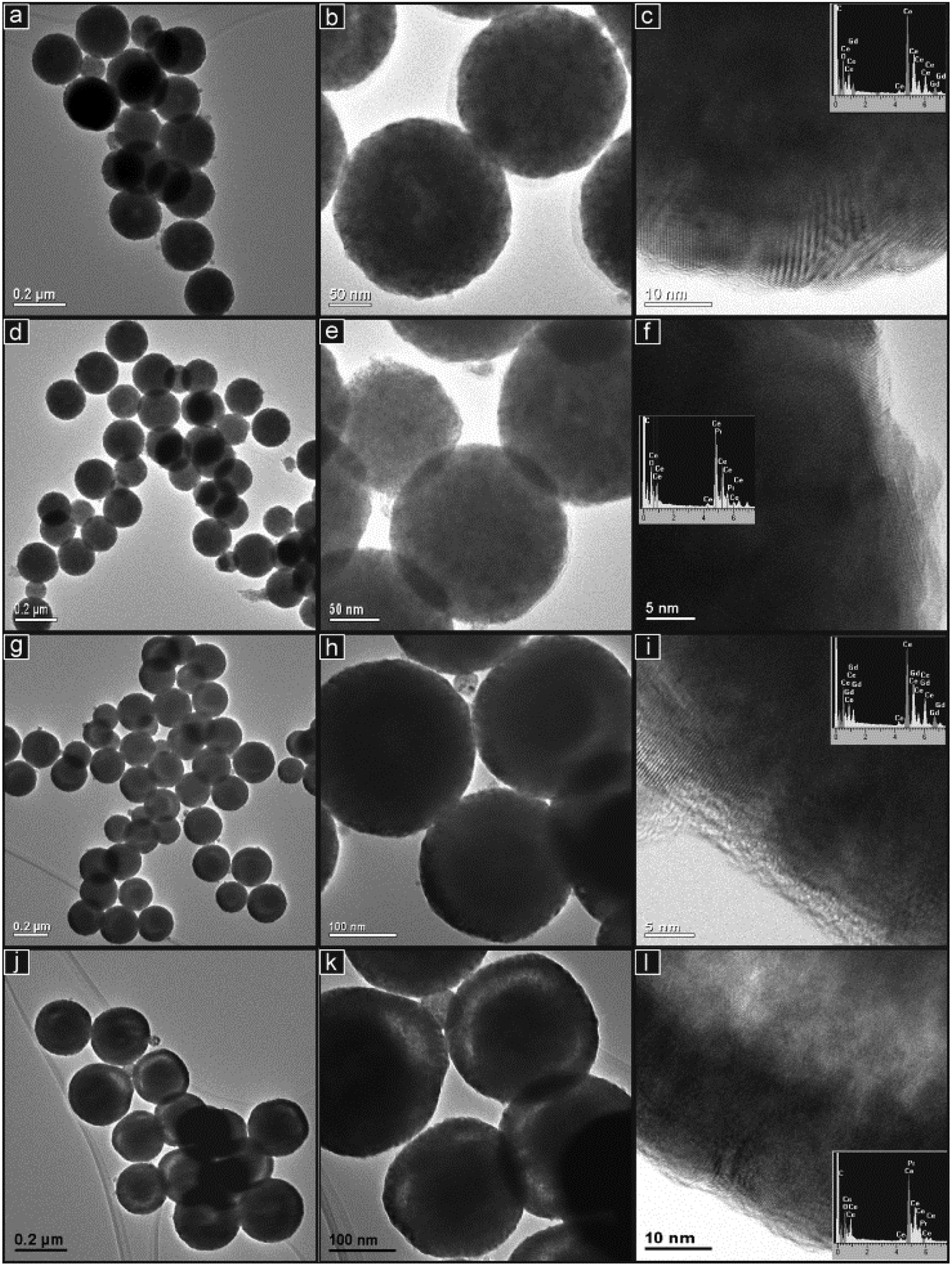 | ||
| Fig. 4 TEM images at increasing magnifications of the samples: (a–c) GDC10; (d–f) PrDC10; (g–i) GDC20; (j–l) PrDC20. EDS spectra taken from areas containing clusters of particles for each composition are inset. | ||
These are seen close to the centre of a minority of the particles in GDC10 (Fig. 4(a) and (b)) and to a lesser extent in the PrDC10. In the samples with 20% doping, these low contrast features were more common but appeared as approximately ring-shaped structures closer to the surface of the spheres and concentric with them. This phenomenon is seen clearly in Fig. 4(g) and (h) for GDC20 and is clear particularly in the PrDC20 particles, shown in Fig. 4(j) and (k). The high magnification image in Fig. 4(l) clearly shows a transition from dark material near the surface of the sphere through a zone of lighter contrast and then into a further region of dark contrast closer to the centre of the sphere. This is consistent with a dense outer shell, a low density region of pores or cavities inside this and a dense inner core. Because open pores were only very rarely observed in the SEM images, it can be concluded that these cavities are internal structures. The EDS spectra (inset in Fig. 4) were obtained from areas of each sample which contained clusters of spherical particles. These spectra demonstrate that both samples contained the elements expected and showed negligible levels of impurities. X:Ce ratios obtained from these spectra are presented in Table 2. For the Pr-doped materials, there is reasonable agreement between these data and those obtained from the SEM study. However, the EDS spectra obtained in the TEM for the two Gd-doped compositions gave considerably higher values than in the SEM study. This suggests that there may have been some variations in chemical composition in these samples on the scale of the EDS study in TEM (areas of 0.5–1 μm in diameter). To study the chemical composition in more detail, EDS mapping was performed. Fig. 5 presents images of small clusters of spherical particles of GDC10 and GDC20 together with the corresponding EDS maps showing the distributions of the elements Ce, O and Gd. The distributions of these elements appear to be coincident, indicating that the samples are compositionally homogeneous within the resolution of the elemental mapping method. Although the ring-shaped features of brighter contrast are seen in both images, it is not clear whether these also appear in the elemental maps.
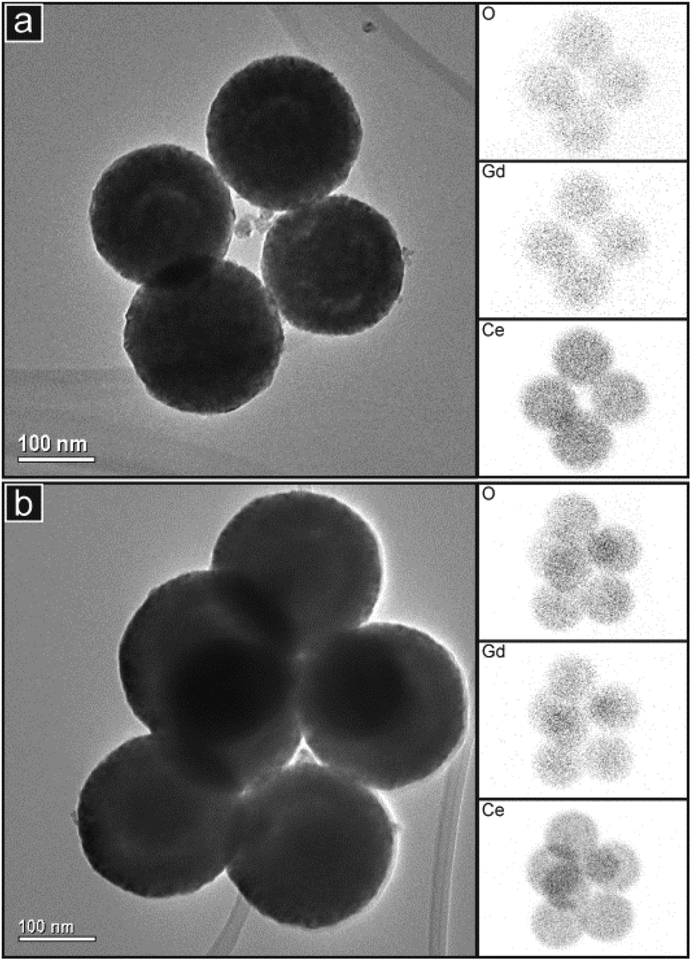 | ||
| Fig. 5 TEM images of groups of spherical particles of (a) GDC10 and (b) GDC20 with corresponding EDS maps of the elements indicated. The EDS maps are rotated by about 20° with respect to the images because of the relative alignment of the EDS detector and the TEM. | ||
Corresponding elemental maps for Pr are not presented because the main peaks of Pr overlap with those of Ce in the EDS spectra (inset spectra in Fig. 4(f) and (l)). However, distribution maps of Ce can still be obtained, as shown in Fig. 6 for PrDC20. Here it is clear that the lighter regions in the image of the single particle and of each of the three spheres in the cluster (Fig. 6(a) and (b), respectively) are also seen in the corresponding distribution maps of Ce and O. This confirms that the light regions often seen inside the spherical particles in the TEM images relate to cavities within the spheres rather than to instrumental artefacts such as those caused by the variation of thickness of samples in TEM. In GDC10 a small proportion of the spherical particles appear to contain small, central pores, whereas in GDC20 and PrDC20, a relatively large proportion of the particles seem to contain cavities, but these appear as rings of light contrast around the centre of the sphere. This suggests that in some cases a small central pore is present but in other cases the central pore is larger and partly filled, particularly close to its own centre.
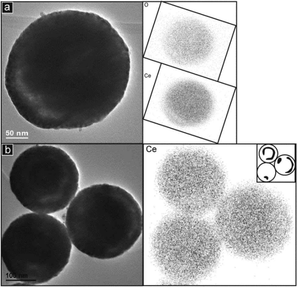 | ||
| Fig. 6 TEM images of the PrDC20 sample with corresponding EDS maps of the elements indicated: (a) A single spherical particle with one apparent cavity (b) A group of three spherical particles with inset indicating the positions of the main apparent cavities. Rotation of the EDS maps with respect to the images has been corrected. | ||
Room temperature SR-XRD and XANES studies
A crystallographic study was performed by Rietveld refinement of the synchrotron radiation X-ray diffraction (SR-XRD) data employing the FullProf Suite software.24 For the cubic phase, the Fm3m space group was assumed with (Gd3+, Pr3+, Ce4+) cations and O2− anion in 4a and 8c positions, respectively. The peak shape was assumed to be a pseudo-Voigt function. The background of each profile was fitted using a six-parameter polynomial function in (2θ)n, n = 0–5. The thermal parameters were assumed to be equal. In Fig. 7(a–d), SR-XRD patterns recorded at room temperature for the nanostructured GDC10, GDC20, PrDC10 and PrDC20 samples, respectively, the Rietveld fitted patterns (line) and the difference plots are presented. The results of Rietveld refinement of the SR-XRD data for the nanostructured samples are summarized in Table 3. In this table, the refinements are accompanied by reliability indices to judge the fitting quality. These indices are weighted R (Rwp), the reduced chi-squared (χ2), and Re are related just to the profile of the XRD patterns, and Rp is related to the crystal structure. The reduced chi-squared is defined by (Rwp/Re)2, where Rwp is the index that should be analyzed to verify if the refinement is converging and Re is the expected statistical value for Rwp.25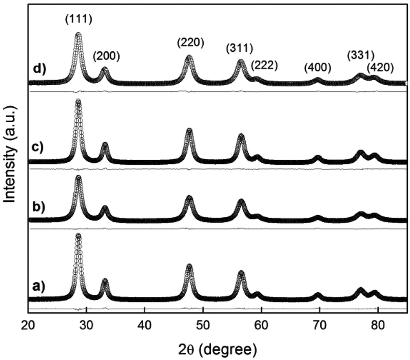 | ||
| Fig. 7 Synchrotron XRD pattern recorded at room temperature in air (empty circles) with the Rietveld-fitted pattern (line) and the difference plot for (a) GDC10, (b) GDC20, (c) PrDC10 and (d) PrDC20. | ||
| Sample | GDC10 | GDC20 | PrDC10 | PrDC20 |
|---|---|---|---|---|
| a (Å) | 5.4213(6) | 5.4238(4) | 5.4214(6) | 5.4278(6) |
| V (Å3) | 159.336(3) | 159.562(4) | 159.343(3) | 159.909(2) |
| R p | 3.49 | 3.47 | 2.88 | 2.95 |
| R wp | 4.11 | 4.18 | 3.65 | 3.77 |
| R e | 2.67 | 2.75 | 2.58 | 2.35 |
| χ 2 | 2.37 | 2.32 | 2.00 | 2.57 |
At room temperature, the lattice parameter of GDC10 (5.4213 Å) was larger than that for pure ceria (5.4117 Å), but it was smaller than that of GDC20 (5.4238 Å). This is as expected because it is acknowledged that the lattice parameter is strongly dependent on the radius of the dopant cation and, as the ionic radius of Gd3+ (1.05 Å) is larger than that of Ce4+ (0.97 Å), it is assumed that substitution of Gd into the ceria lattice leads to lattice expansion.
The ionic radius of Pr3+ (1.13 Å) is larger than both Ce4+ (0.97 Å) and Gd3+ (1.05 Å). Therefore, substitution of Pr3+ into the ceria lattice might be expected to lead to lattice expansion and, moreover, to a larger increase in lattice parameter than for GDC. The lattice parameter of PrDC20 (5.4268 Å) is indeed larger than that of GDC20 (5.4238 Å). However, the lattice parameter of PrDC10 (5.4214 Å) is similar to that of GDC10 (5.4213 Å). This behavior may be explained by the fact that Pr is stable as both Pr4+ and Pr3+. The radius of Pr4+ (0.96 Å) is slightly smaller than that of Ce4+ (0.97 Å). This indicates that a significant proportion of the Pr might be present as Pr4+ in these solid solutions (at room temperature in air).
In addition to the direct effect of cation substitution, the concentration of oxygen ion vacancies – itself increasing with the extent of aliovalent doping level – would also cause expansion of the ceria lattice, according to Chen et al.26 It is clear that all of the Ln-doped ceria materials show lattice expansion resulting from a combined effect of the substitution of Ce by Gd or Pr and of the corresponding increase in oxygen vacancy concentration.
In the X-ray absorption spectroscopy experiments, it is important to mention that, in the PrDC system, the spectra at the Pr L3 and Ce L3-edges were collected simultaneously, without any interruption or change in the experimental setup, which could influence the reaction conditions. As expected, the Ce L3-edge is more intense than the Pr L3-edge, reflecting the Ce:Pr ratio in the samples studied (Fig. 8). Moreover, it is clear that the absorption at the Pr L3-edge is more intense for PrDC20 than for PrDC10.
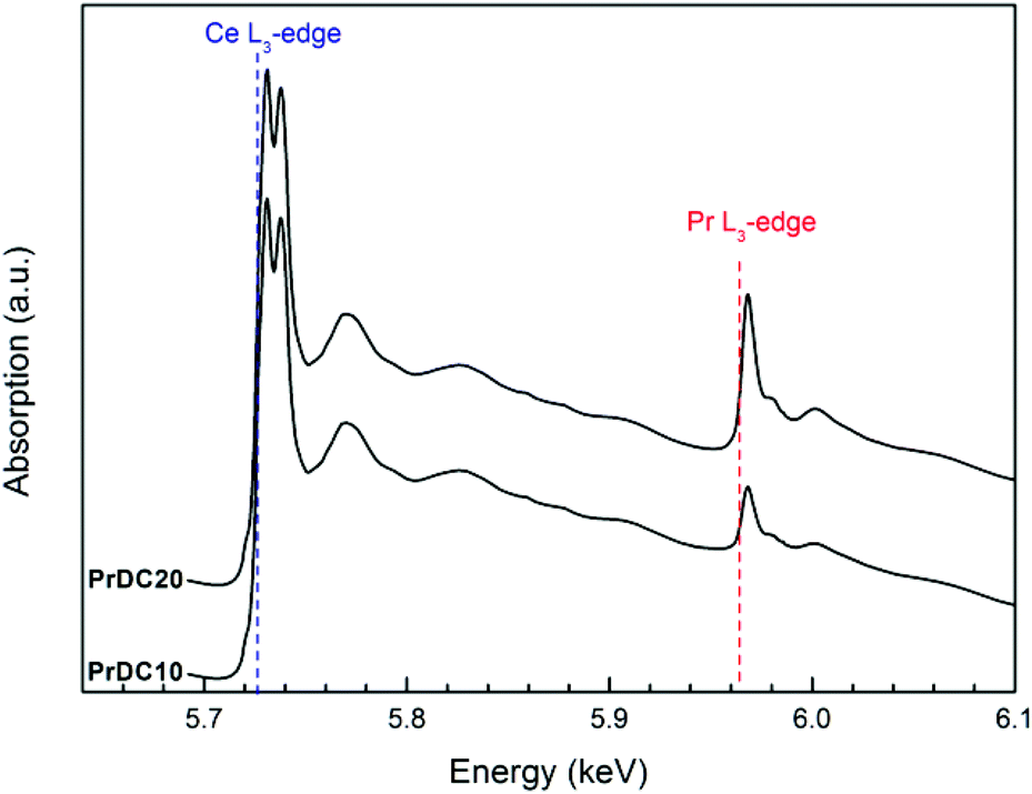 | ||
| Fig. 8 X-ray absorption spectra obtained at room temperature for PrDC10 and PrDC20. The Ce L3-edge and the Pr L3-edge are indicated. | ||
In Fig. 9(a), normalized Ce L3-edge XANES spectra of the nanostructured GDC10, GDC20, PrDC10 and PrDC20 spheres in air at room temperature are exhibited. For comparison, the spectrum corresponding to a CeO2 nanopowder is included in this figure. For pure CeO2, the Ce L3-edge exhibits two clear peaks frequently labelled A and B. Peak A is assigned for a Ce4+ peak with the final state 2p4f05d1, which denotes that an electron is excited from the Ce 2p shell to its 5d shell, with no electron in the 4f shell. Peak B is also a Ce4+ peak, with the final state 2p4f15d1v, which denotes that in addition to an electron excited from the Ce 2p shell to the 5d shell, another electron is also excited from the valence band (O 2p shell) to the Ce 4f shell, leaving a hole (v) in the valence band. Some authors refer to Peak C as a Ce3+ peak.19 An additional small peak (D) is present at pre-edge and probably arises from transitions to the bottom of the conduction band.
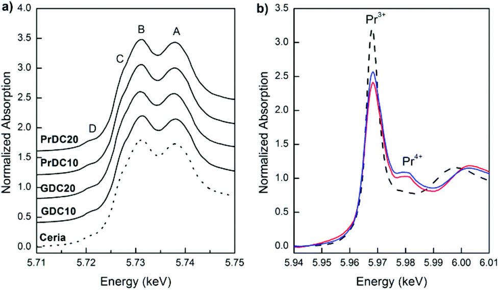 | ||
| Fig. 9 Normalized XANES spectra obtained at room temperature (a) at the Ce L3-edge for GDC10, GDC20, PrDC10 and PrDC20, and (b) at the Pr L3-edge for PrDC10 (red line) and PrDC20 (blue line). Spectra for CeO2 nanopowder (dashed line) and Pr(NO3)3 (Pr3+; dotted line) are included for comparison in (a) and (b), respectively. | ||
Clearly, no large differences are observed between the spectra in Fig. 9(a). The Ce L3-absorption edges for all samples are close to 5725.7 eV (values determined from the first and second derivatives of the Ce L3-edge XANES spectra for each sample). However, the normalized Pr L3-edge XANES spectra (Fig. 9(b)) clearly show the white lines corresponding to Pr3+ and Pr4+. This indicates the presence of both Pr3+ and Pr4+ in the solid solution, supporting the previous assumption about the lattice parameters of PrDC10 and PrDC20 obtained by SR-XRD.
In order to investigate these effects further, SR-XRD and XANES experiments were performed on these materials in situ in both reducing and oxidizing environments.
In situ SR-XRD studies
In Fig. 10, lattice parameters at room temperature in air and at 500 °C under reducing and oxidizing conditions are shown. In all cases, the lattice parameters were refined assuming a cubic phase (Fm3m space group) by the Rietveld method (ESI, Tables S1–S4†). For comparison, lattice parameters corresponding to CeO2 nanopowder are included in this figure. When the samples were heated from room temperature to 500 °C under oxidizing conditions (synthetic air), a thermal expansion of the unit cell was observed in all samples, as expected. On switching to reducing conditions (5% H2/He) at the same temperature, the lattice parameters were seen to increase for all samples, but to different extents. Clearly, the unit cell parameter is strongly dependent on the identity and concentration of the cation dopant as well as on the gas atmosphere and temperature.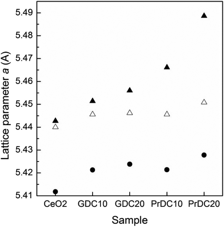 | ||
| Fig. 10 Lattice parameters estimated from Rietveld refinement at room temperature in air (black circles) and at 500 °C under reducing (black triangles) and oxidizing (empty triangles) atmospheres for nanostructured GDC10, GDC20, PrDC10 and PrDC20 spheres. Data for CeO2 nanopowder are included for comparison. | ||
In the case of GDC10, the lattice parameter increased from 5.4456 Å (oxidizing) to 5.4514 Å (reducing), whereas for GDC20, the lattice parameter increased from 5.4462 Å (oxidizing) to 5.4560 Å (reducing). This change can be ascribed mainly to the increase in the concentration of Ce3+ in the Ce–Gd–O solid solutions under reducing conditions (and to the associated increase in oxygen ion vacancy concentration), because the dopant cation, Gd3+, has no accessible oxidation state other than +3. The changes in lattice parameter in the nanostructured PrDC spheres are considerably larger than those observed in GDC (Fig. 10). In the case of PrD10, the lattice parameter increased from 5.4456 Å (oxidizing) to 5.4661 Å (reducing), whereas for PrDC20 it increased from 5.4508 Å (oxidizing) to 5.4887 Å (reducing). In this case, other effects could be directly involved with these changes, which cannot be attributed only to the increase in Ce3+ concentration in the PrDC lattice under reducing conditions. The proposed explanation is as follows: in contrast to the GDC case, here the dopant cation, Pr, has two stable oxidation states, +3 and +4. Hence, if it is reduced, that explains the observed shift in lattice parameter to a higher value both because the Pr3+ ion is considerably larger than the Pr4+ and because additional oxygen ion vacancies are likely to be formed to balance the overall decrease in cationic charge, causing a further lattice expansion. Reduction of both Ce and Pr to their +3 states would introduce extrinsic oxygen vacancies into the system, and it should be noted that the number of vacancies is evidently related to the amount of Ce3+ and Pr3+. In other words, the number of vacancies is not arbitrary, and because Pr3+ is more stable than Ce3+, the lattice expansion in reducing atmospheres is (barring thermal expansion effects) probably ascribable mainly to the Pr3+ content.27,28 Furthermore, in an oxide lattice environment, Pr can exist in several metastable intermediate oxide phases, each with a different composition and with decreasing oxygen content, as the oxygen partial pressure is lowered.29,30 It should be noted that the Ce cation in undoped ceria, despite having an inherently high tendency to switch between +3 and +4 oxidation states in response to the oxidizing/reducing environment, has no access to intermediate metastable oxide phases at all.29,30
From the above, it can be inferred that, in a reducing environment, the PrDC system has a marked tendency to favour the presence of the Pr3+ state, giving rise to the lattice expansion observed. Increasing the Pr dopant content gave rise to a more marked effect, thus explaining the larger lattice expansion on reduction of PrDC20 than of PrDC10.
Finally, it is important to mention that the average crystallite size increased from 10 to 14 nm for GDC10 and PrDC10 and from 8 to 12–13 nm for GDC20 and PrDC20. The intensity of the 111 reflection, used to determine the crystallite size from the Scherrer formula, increased during the in situ SR-XRD experiments under the different thermochemical conditions applied (ESI, Fig. S1–S4†). Although all samples were previously calcined at 500 °C in air for 1 h, the crystallites appeared be continue to grow under the measurement conditions. In particular, the samples were compacted in the sample holder, achieving a closer contact between particles and this could have contributed to increasing the crystallite size.
In situ XANES studies
In order to determine the fraction of Ce present as Ce3+ in the samples, data analysis was conducted by least-squares fitting four Gaussian profiles and one arctangent function to the experimental XANES data in the range between 5710 and 5750 eV. The assignment of the four peaks in this region was discussed in a previous section. The ratio between the area of peak C (associated with Ce3+) and the sum of the areas of peaks A, B and C (A and B are associated with Ce4+) gives direct information about the fraction of Ce present as Ce3+.31In Fig. 11(a) and (b), the Ce L3-edge XANES spectra of the nanostructured PrDC10 spheres at 500 °C under reducing (5% H2/He, 20 mL min−1) and oxidizing (synthetic air: 21% O2/N2, 50 ml min−1) conditions, and their corresponding fits are shown. Similar figures for GDC10, GDC20, and PrDC20 are given in Fig. S5a–f (ESI†). The increase in the area of peak C indicates that, under these reducing conditions, the amount of Ce present as Ce3+ at high temperature is larger than in the same sample under oxidizing conditions.
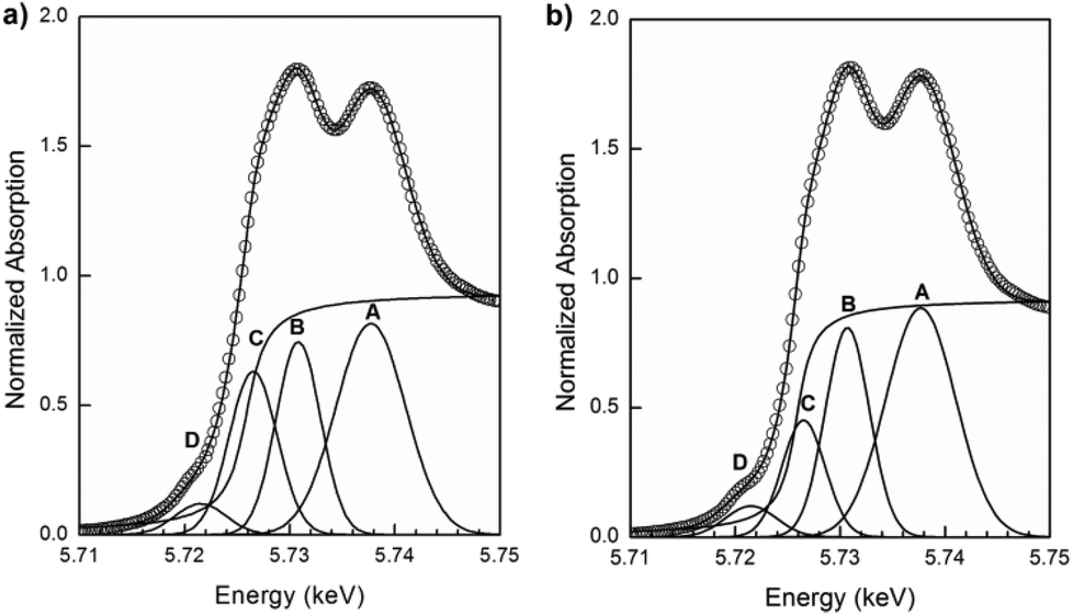 | ||
| Fig. 11 Normalized XANES spectra at the Ce L3-edge for PrDC10 at 500 °C under (a) reducing and (b) oxidizing conditions showing the experimental data (empty circles), four Gaussian peaks (A–D), one arctangent function obtained by least-squares fitting and the sum of all five functions (continuous line). | ||
The fractions of Ce3+/(Ce4+ + Ce3+) in the LnDC samples under reducing and oxidizing conditions at 500 °C are presented in Table 4. As expected, in both Gd- and Pr-doped samples, only small amounts of Ce3+ are seen in the oxidizing environment and these levels increase considerably on exposing the samples to H2. In both cases, again, the Ce3+ fraction decreases with increasing dopant content, more markedly in the PrDC system. In this connection, it should be noted that the SSA values markedly decreased on going from the LnDC10 to the LnDC20 samples. In nanostructured materials, the surface area-volume relationship is important in that it affects both the coordination number and the local symmetry of surface ions. In ceria-based samples, high surface area results in a higher proportion of low-coordination Ce ions, which gives rise to a higher Ce3+ content. Hence, the marked drop in SSA values with increasing Gd and Pr content would explain a sharp decrease in the Ce3+ content for the LnDC20 samples, and the resulting low Ce3+ fractions observed.
| Sample | Atmosphere | Ce3+/(Ce4+ + Ce3+) % |
|---|---|---|
| GDC10 | 5% H2/He | 7.2 |
| 21% O2/N2 | 1.8 | |
| GDC20 | 5% H2/He | 6.4 |
| 21% O2/N2 | 0.1 | |
| PrDC10 | 5% H2/He | 8.4 |
| 21% O2/N2 | −0.2 | |
| PrDC20 | 5% H2/He | 5.3 |
| 21% O2/N2 | 0.5 |
Fig. 12 presents the Pr L3-edge XANES spectra of the nanostructured PrDC10 and PrDC20 spheres at 500 °C under reducing (5% H2/He, 20 mL min−1) and oxidizing (synthetic air: 21% O2/N2, 50 ml min−1) conditions. At first sight, it could be assumed that the extent of dynamic re-oxidation (seen as the Pr3+ switching to Pr4+ in oxidizing atmospheres) of these samples is rather low, because the white line assigned to Pr4+ is rather small. However, there are studies that show that even in XANES spectra of samples containing (nominally) 100% of the Pr in the +4 state, the white line for Pr4+ is not so pronounced, and that the presence of any peak should be taken as indicative of significant Pr4+ content.32 Hence, our samples show significant levels of both Pr3+ and Pr4+, in good agreement with the in situ SR-XRD results and the explanations of these given above. To a first approximation, the ratios of the corresponding peak areas indicate that the Pr3+:Pr4+ ratios in the PrDC10 and PrDC20 samples are similar to each other under oxidizing conditions and similar but higher under reducing conditions.
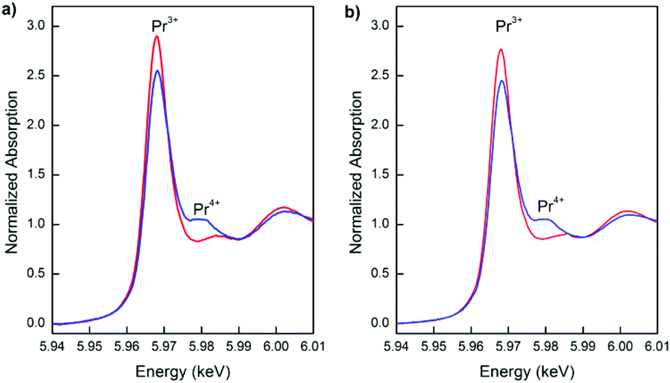 | ||
| Fig. 12 Normalized XANES spectra at the Pr L3-edge taken at 500 °C under reducing (red line) and subsequent oxidizing (blue line) conditions for a) PrDC10 and b) PrDC20. | ||
It is important to summarize the in situ SR-XRD results and the Pr L3-edge XANES results, because they both point to a common tendency. From the in situ SR-XRD results, it can be inferred that the PrDC system has a tendency to favour the presence of the Pr3+ state under reducing conditions, as shown by the lattice expansion observed in dilute H2 at 500 °C. Increasing the Pr dopant content, going from PrDC10 to PrDC20, increases this effect. Pr L3-edge XANES results show an important Pr3+ content in a reducing environment, which is in good agreement with the in situ SR-XRD results. The data in Table 4 show that the lattice expansion of the Pr-containing samples cannot be attributed to the fraction of Ce present as Ce3+ because a considerably larger increase than for the GDC samples would be required but was not observed. In fact, increasing the Pr dopant fraction appeared to stabilize Ce in the Ce4+ state, very probably because of the higher stability of the Pr3+ state than of the Ce3+ state.27,33 This implies that the majority of changes observed upon the reduction of the PrDC samples are explained by the tendency of Pr to switch to the +3 oxidation state, in preference to the reduction of Ce4+ to Ce3+.
Conclusions
In the present work, nanostructured LnxCe1−xO2−δ (Ln: Gd and Pr; x = 0.1 and 0.2) spheres were synthesized by microwave assisted hydrothermal homogeneous co-precipitation. All samples were characterized by XRD, XANES, HRTEM and EDS.Electron microscopy images confirmed the formation of well-structured and uniform spherical particles for all four compositions studied. Homogeneous elemental compositions were verified in both compositions by EDS elemental mapping of individual spheres in TEM. The spheres were composed of nanocrystallites, whose average diameter was calculated from the XRD results to be 8 and 10 nm for the LnDC10 and LnDC20 materials, respectively. Crystallites viewed in the TEM images had diameters that agreed with these values. Sphere diameters were measured from the SEM images and were remarkably uniform in each sample. Average diameters fell in the range 187–255 nm, the larger being for the higher doping levels and for GDC over PrDC. In a very small number of particles, surface pores were evident. HRTEM images and corresponding elemental maps provided evidence for the presence of internal cavities in some spheres, particularly in the PrDC20 material.
In situ XRD experiments showed an increase in lattice parameters upon reduction, which was attributed to the reduction of Ce4+ and Pr4+ cations to Ce3+ and Pr3+, which have larger radii, and to the associated increase in VO concentration. This increase in lattice parameter was considerably more pronounced for PrDC than for GDC, and was explained by the considerably larger change in ionic radius for Pr upon reduction.
Ce and Pr L3-edge XANES absorption experiments showed that the changes observed upon the reduction of the Pr-containing samples resulted mostly from the formation of Pr3+ rather than Ce3+, and supported the previously-reported proposal that Pr3+ acts to stabilize Ce4+ to some extent.
Acknowledgements
This work has been supported by the Brazilian Synchrotron Light Laboratory (LNLS, Brazil), under proposals D04B-XAFS1-13435 and D12A-XRD1-13437. AgenciaNacional de PromociónCientífica y Tecnológica (Argentina, PICT 2012-1506). Electron Microscopy was performed at the Electron Microscopy Facility, University of St Andrews. The authors are grateful to Anna Paula da Silva Sotero Levinsky, Cristiane Rodella, Fábio Zambello, Tamiris Boucas Piva and Simone Baú Betim for their invaluable experimental assistance at the LNLS. Dr L.M. Acuña and Dr R.O. Fuentes are members of CIC-CONICET, Argentina.Notes and references
- R. Di Monte and J. Kaspar, Top. Catal., 2004, 28, 47–57 CrossRef CAS.
- S. D. Park, J. M. Vohs and R. J. Gorte, Nature, 2000, 404, 265–267 CrossRef CAS PubMed.
- S. M. Haile, Mater. Today, 2003, 6, 24–29 CrossRef CAS.
- T. Kim, J. M. Vohs and R. J. Gorte, Ind. Eng. Chem. Res., 2006, 45, 5561–5565 CrossRef CAS.
- R. J. Gorte, AIChE J., 2010, 56, 1126–1135 CAS.
- J. A. Kilner, Solid State Ionics, 2000, 123, 13–23 CrossRef.
- B. C. H. Steele, Solid State Ionics, 2000, 129, 95–110 CrossRef CAS.
- B. Dalset, P. Blennov, P. Van Hendriksen, N. Bonannos, D. Lybyeand and M. Mogensen, J. Solid State Electrochem., 2006, 10, 547–561 CrossRef.
- R. O. Fuentes and R. T. Baker, Int. J. Hydrogen Energy, 2008, 33, 3080–3084 CrossRef PubMed.
- V. V. Kharton, F. M. Figueiredo, L. Navarro, E. N. Naumovich, A. V. Kovalevsky, A. A. Yaremchenko, A. P. Viskup, A. Carneiro, F. M. B. Marques and J. R. Frade, J. Mater. Sci., 2001, 36(5), 1105–1117 CrossRef CAS.
- R. O. Fuentes, F. F. Muñoz, L. M. Acuña, A. G. Leyva and R. T. Baker, J. Mater. Chem., 2008, 18, 5689–5795 RSC.
- M. Balaguer, C. Solís and J. M. Serra, J. Phys. Chem. C, 2012, 116, 7975–7982 CAS.
- D. P. Fagg, A. L. Shaula, V. V. Kharton and J. R. Frade, J. Membr. Sci., 2007, 299, 1–7 CrossRef CAS PubMed.
- M. Balaguer, C. Solís, S. Roitsch and J. M. Serra, Dalton Trans, 2014, 43, 4305–4312 RSC.
- M. Balaguer, C. Solís and J. M. Serra, Chem, Mater., 2011, 23, 5184–5196 CrossRef.
- K. Ahn, D. S. Yoo, D. H. Prasad, H.-W. Lee, Y.-C. Chung and J.-H. Lee, Chem. Mater., 2012, 24, 4261–4267 CrossRef CAS.
- H. Borchert, Y. V. Frolova, V. V. Kaichev, I. P. Prosvirin, G. M. Alikina, A. I. Lukashevich, V. I. Zaikovskii, E. M. Moroz, S. N. Trukhan, V. P. Ivanov, E. A. Paukshtis, V. I. Bukhtiyarov and V. A. Sadykov, J. Phys. Chem. B, 2005, 109, 5728–5738 CrossRef CAS PubMed.
- X. Liu, K. Zhou, L. Weng, B. Wang and Y. Li, J. Am. Chem. Soc., 2009, 131, 3140–3141 CrossRef CAS PubMed.
- F. Zhang, P. Wang, J. Koberstein, S. Khalid and S.-W. Chan, Surf. Sci., 2004, 563, 74–82 CrossRef CAS PubMed.
- H. Klug and L. Alexander, in X-ray Diffraction Procedures for Polycrystalline and Amorphous Materials, John Wiley, New York, 1974, p. 618 Search PubMed.
- T. J. Ressler, J. Synchrotron Radiat., 1998, 5, 118–122 CrossRef CAS PubMed.
- R. O. Fuentes and R. T. Baker, J. Power Sources, 2009, 186(2), 268–277 CrossRef CAS PubMed.
- F. F. Muñoz, A. G. Leyva, R. T. Baker and R. O. Fuentes, Int. J. Hydrogen Energy, 2012, 37, 14854–14863 CrossRef PubMed.
- J. Rodríguez-Carvajal, FullProf Suite Program, Version 2.05, Laboratoire León Brillouin, Saclay, France: CEA-CNRS, 2011.
- R. A. Young, in The Rietveld Method, ed. R. A. Young, Oxford University Press, Oxford, 1993, ch. 1, pp. 21–24 Search PubMed.
- L. Chen, P. Fleming, V. Morris, J. D. Holmes and M. A. Morris, J. Phys. Chem. C, 2010, 114, 12909–12919 CAS.
- D. P. Fagg, I. P. Marozau, A. L. Shaula, V. V. Kharton and J. R. Frade, J. Solid State Chem., 2006, 179, 3347–3356 CrossRef CAS PubMed.
- H. L. Tuller, S. R. Bishop, D. Chen, Y. Kuru, J.-J. Kim and T. S. Stefanik, Solid State Ionics, 2012, 225, 194–197 CrossRef CAS PubMed.
- S. Bernal, G. Blanco, J. M. Gatica, J. A. Perez-Omil, J. M. Pintado and H. Vidal, in Binary Rare Earth Oxides, ed. G. Adachi, N. Imanaka and Z.C. Kang, Kluwer Academic Publishers, Dordrecht, 2004, pp. 32–34 Search PubMed.
- S. Ferro, Int. J. Electrochem., 2011, 2011 Search PubMed , 561204.
- F. F. Muñoz, R. T. Baker, A. G. Leyva and R. O. Fuentes, Appl. Catal., B, 2013, 136–137, 122–132 CrossRef PubMed.
- I. A. Sluchinskaya, A. I. Lebedev and A. Erko, Phys. Solid State, 2012, 54(5), 975–979 CrossRef CAS.
- D. P. Fagg, J. R. Frade, V. V. Kharton and I. P. Marozau, J. Solid State Chem., 2006, 179, 1469–1477 CrossRef CAS PubMed.
Footnote |
| † Electronic supplementary information (ESI) available: Structural parameters and standard Rietveld agreement factors for nanostructured LnDC spheres are presented in Tables S1–S4, SR-XRD patterns in the vicinity of the 111 reflection for nanostructured LnDC spheres are exhibited in Fig. S1–S4 and the Ce L3-edge XANES spectra of the nanostructured GDC10, GDC20, and PrDC20 spheres at 500 °C under reducing (5% H2/He, 20 mL min−1) and oxidizing (synthetic air: 21% O2/N2, 50 ml min−1) conditions, and their corresponding fits are shown in Fig. S5a–f. See DOI: 10.1039/c4nr05630b |
| This journal is © The Royal Society of Chemistry 2015 |