Synthesis, optical and electrochemical properties of the A–π-D–π-A porphyrin and its application as an electron donor in efficient solution processed bulk heterojunction solar cells
Challuri
Vijay Kumar
a,
Lydia
Cabau
a,
Emmanuel N.
Koukaras
bc,
Ganesh D.
Sharma
*d and
Emilio
Palomares
*ae
aInstitute of Chemical Research of Catalonia (ICIQ), Avda. Països Catalans 16, E-43007 Tarragona, Spain
bInstitute of Chemical Engineering Sciences, Foundation for Research & Technology, Hellas, Stadiou Str. Platani, Patras, 26504, Greece
cMolecular Engineering Laboratory, Department of Physics, University of Patras, Patras, 26500, GR, Greece
dR & D Center for Engineering and Science, JEC group of Colleges, Jaipur Engineering College, Kukas, Jaipur 303101, India. E-mail: gdsharma273@gmail.com; sharmagd_in@yahoo.com
eCatalan Institution for Research and Advance Studies (ICREA), Avda. Lluis Companys 23, E-08010 Barcelona, Spain. E-mail: epalomares@iciq.es
First published on 30th October 2014
Abstract
A conjugated acceptor–donor–acceptor (A–π-D–π-A) with the Zn-porphyrin core and the di-cyanovinyl substituted thiophene (A) connected at meso positions denoted as VC62 was designed and synthesized. The optical and electrochemical properties of VC62 were investigated. This new porphyrin exhibits a broad and intense absorption in the visible and near infrared regions. Bulk-heterojunction (BHJ) solution processed organic solar cells based on this porphyrin, as electron donor material, and PC71BM ([6,6]-phenyl C71 butyric acid methyl ester), as electron acceptor material, were fabricated using THF and a pyridine–THF solvent exhibiting a power conversion efficiency of 3.65% and 5.24%, respectively. The difference in efficiencies is due to the enhancement of the short circuit current Jsc and FF of the solar cell, which is ascribed to a stronger and broader incident photon to current efficiency (IPCE) response and a better balanced charge transport in the device processed with the pyridine–THF solvent.
Introduction
In recent years, organic solar cells based on bulk heterojunction (BHJ) active layers have attracted much attention because of their advantages for the solution processability of the active layer, potential low cost, light weight, flexibility and their applications in large area devices.1 Organic BHJ solar cells based on conjugated polymers as electron donor materials and fullerene derivatives as electron acceptor materials have made great progress in achieving high power conversion efficiency (PCE) by optimizing the structure of conjugated polymers and device architecture. Recently, the encouraging PCE close to 10% has been reported for the organic solar cell based on polymer donors and acceptors.2 In spite of this high performance of the solar cells based on polymers, there are disadvantages for polymer donors, for example, the high molecular weight dispersity and the batch-to-batch reproducibility.3 Comparing with polymers, small molecules possess the advantages of a well-defined molecular structure, definite molecular weight, easier purification and good reproducibility.4 In recent years, various types of small molecule donors have been designed and employed as a donor for the fabrication of BHJ organic solar cells.5 To date, the highest PCEs of solution processed OSCs based on small molecule donors and fullerene acceptors are >9%.6 However, the PCE has to be further improved for the commercialization of organic solar cells based on small molecules. Remarkably, there has been a recent report of a small molecule based organic solar cell with a record breaking 12% cell efficiency,7 rendering the small molecule based BHJ organic solar cell devices as strong competitors to their counterparts based on polymer donors.Photosynthetic pigments related to the chlorophylls, such as porphyrins, are particularly good candidates for optical and optoelectronic applications, due to their large molar absorption coefficients, tunable electro-chemical and photophysical properties via central metal insertion and/or introduction of various substituents at the macrocycle peripheral positions.8 The unique properties of porphyrins, including strong Soret and moderate Q bands,9 fast electron injection, and good photophysical and thermal stability, make them ideal candidates for photovoltaic applications.10 Despite the successful utilization of porphyrins as sensitizers for dye sensitized solar cells11 (some of them have displayed a record PCE of 12.3%12 and 13%11) and in vacuum processed organic solar cells,13,14 the use of the porphyrins as donors in solution processed BHJ solar cells is very limited due to the difficulty of their solubility in most of the common organic solvents. One of the most important requirements of materials used in the BHJ active layer for the solution processed organic solar cell is their high solubility in common organic solvents. However, the appropriate selection of peripheral substituents can increase the solubility of porphyrins. Matsuo et al. have reported the synthesis of soluble porphyrins bearing tetraethyl porphyrin cores15 with two aromatic and two aliphatic groups in trans positions and used them as donors along with PC60BM as the electron acceptor for solution processed BHJ organic solar cells and achieved a PCE of 2.5% with a high open circuit voltage of 0.92 V. Huang et al. have used a conjugated D–A porphyrin containing benzothiadiazole end capped with 3-hexylthienyl linked by an ethylene bridge to a porphyrin core, as the donor along with PC71BM as the acceptor for BHJ solar cells and reported a PCE of 4.02%.16 Peng and co-workers, by employing a porphyrin with two diketopyrrolopyrrole units and ethynyl bridges at meso positions, along with PC60BM as the electron acceptor, reported a BHJ organic solar cell with a PCE value of 3.71%, which was significantly improved to 4.78% when the BHJ active layer was processed with pyridine.17 Sharma et al. have recently employed a porphyrin derivative with an ethynlpyridiyl group at a meso position, as the donor along with PC70BM as the acceptor for solution processed BHJ organic solar cells and achieved a PCE of 2.54%.18 Recently, Peng et al. employed a porphyrin molecule with less bulky substituents at the periphery as donor material along with PC61BM as the acceptor for solution processed organic solar cells and achieved a PCE up to 7.23%.19
The thiophene group has been used in metal free organic solar cells20 to enhance the absorption coefficient of the dye and red-shift its absorption spectrum. This concept has been adopted for porphyrin based DSSC. Thiophene units were used in both β-linked21 and meso linked22 porphyrin sensitizers to give efficiencies of 4.0% and 5.1%, respectively. The cyano (CN)-group is a strong electron withdrawing unit that has been widely adopted in small molecules.23 The introduction of the CN group in the small molecules changes their physical, electrochemical and optical properties and photovoltaic performances. Using a strong π-electron withdrawing moiety provides the possibility to control the absorption spectrum in the near infrared region via conjugation with electron rich aromatic units, and its rigid and planar aromatic structure helps to enhance the inter-chain packing of a resulting molecule and therefore leads to very high charge carrier mobility.
Chen et al. have used an A–D–A small molecule, which consists of a conjugated donor backbone main chain and acceptor terminal units as donors for the BHJ solution processed solar cell, and achieved a PCE over 8%.24 An acceptor–donor–acceptor (A–π–D–π–A) molecular structure with a conjugated donor backbone and an electron-withdrawing terminal has several advantages for use in BHJ devices: (1) high mobility with the planar structure and efficient π–π interactions; (2) a low band gap resulting from the intramolecular charge transfer and (3) good film quality owing to a long conjugated backbone with dispersed alkyl chains similar to polymers. In this context, we report the design and synthesis of an A–π-D–π-A porphyrin small molecule in which the di-cyanovinyl substituted thiophene (A) was linked by ethynylene to the porphyrin core with high solubility. Dicyanovinyl is a strong electron withdrawing unit used in many small molecule organic semiconductors. The ethynylene link makes the dicyanovinyl substituted thiophene moiety coplanar to the porphyrin core thus promoting an extensive π-conjugated region. We have used this porphyrin small molecule as a donor along with the PC71BM as the acceptor for the fabrication of BHJ solution processed organic solar cells. Moreover, we have shown that the nanomorphology of the VC62![[thin space (1/6-em)]](https://www.rsc.org/images/entities/char_2009.gif) :
:![[thin space (1/6-em)]](https://www.rsc.org/images/entities/char_2009.gif) PC71BM active layer could be improved by the solvent additive pyridine with an enhanced balanced charge transport and the PCE of up to 5.34% has been achieved for the optimized BHJ organic solar cell.
PC71BM active layer could be improved by the solvent additive pyridine with an enhanced balanced charge transport and the PCE of up to 5.34% has been achieved for the optimized BHJ organic solar cell.
Experimental details
Characterization techniques
UV-vis absorption spectra were measured in a 1 cm path-length quartz cell using a Shimadzu model 1700 spectrophotometer. 1H NMR spectra were recorded at 300 MHz on a Bruker 300Avance NMR spectrometer with X-WIN NMR software. 1H spectra were referenced to tertramethylsilane. ESI mass spectra were recorded on a Water Quattro micro (Water Inc., USA). Cyclic voltammetric experiments were carried out with a PC-controlled CH instruments model CHI620C electrochemical analyzer.Materials
Dichloromethane, pyrrole, pyridine, dichloroethane, ethanol and THF were distilled before use. The 3,5-tert-butyl benzaldehyde, β-alanine, malononitrile DDQ, Pd2(dba)3, AsPh3, N-bromosuccinimide (NBS), NEt3, were purchased from Sigma-Aldrich. These precursors are used to synthetize compound 4 as in ref. 25.Synthesis of porphyrin VC62
![[thin space (1/6-em)]](https://www.rsc.org/images/entities/char_2009.gif) :
:![[thin space (1/6-em)]](https://www.rsc.org/images/entities/char_2009.gif) 1). Compound 3 was obtained in 74% yield. 1H NMR (300 MHz, chloroform-d) δH: 7.74 (s, 1H), 7.50 (d, J = 4.1 Hz, 1H), 7.24 (d, J = 4.1 Hz, 1H). 13C NMR (126 MHz, CDCl3) δ 140.60, 129.38, 127.32, 122.56, 117.09, 104.10, 103.27, 69.06.
1). Compound 3 was obtained in 74% yield. 1H NMR (300 MHz, chloroform-d) δH: 7.74 (s, 1H), 7.50 (d, J = 4.1 Hz, 1H), 7.24 (d, J = 4.1 Hz, 1H). 13C NMR (126 MHz, CDCl3) δ 140.60, 129.38, 127.32, 122.56, 117.09, 104.10, 103.27, 69.06.
![[thin space (1/6-em)]](https://www.rsc.org/images/entities/char_2009.gif) :
:![[thin space (1/6-em)]](https://www.rsc.org/images/entities/char_2009.gif) 4) to afford the pure product as a green solid (22 mg, yield 32%). 1H NMR (300 MHz, THF-d8) δH 9.85 (d, J = 4.6 Hz, 4H), 9.14 (d, J = 4.6 Hz, 4H), 8.12(S, 2H), 8.31 (d, J = 1.7 Hz, 4H), 8.14 (d, J = 3.4 Hz, 2H), 8.1 (d, J = 4.0 Hz, 2H), 8.05 (d, J = 4.4 Hz, 2H), 1.79 (S, 36H). MALDI-TOF (m/z): [M] calculated for C68H56N8S2Zn: 1112.3361, found 1112.3256.
4) to afford the pure product as a green solid (22 mg, yield 32%). 1H NMR (300 MHz, THF-d8) δH 9.85 (d, J = 4.6 Hz, 4H), 9.14 (d, J = 4.6 Hz, 4H), 8.12(S, 2H), 8.31 (d, J = 1.7 Hz, 4H), 8.14 (d, J = 3.4 Hz, 2H), 8.1 (d, J = 4.0 Hz, 2H), 8.05 (d, J = 4.4 Hz, 2H), 1.79 (S, 36H). MALDI-TOF (m/z): [M] calculated for C68H56N8S2Zn: 1112.3361, found 1112.3256.
Device fabrication and characterization
The BHJ organic solar cells were fabricated using the glass/ITO/PEDOT:PSS/VC62![[thin space (1/6-em)]](https://www.rsc.org/images/entities/char_2009.gif) :
:![[thin space (1/6-em)]](https://www.rsc.org/images/entities/char_2009.gif) PC71BM/Al device structure. The ITO coated glass substrates were cleaned ultrasonically and subsequently in aqueous detergent, de-ionized water, isopropyl alcohol and acetone and finally dried under ambient conditions. An aqueous solution of PEDOT:PSS (Heraeus, Clevious P VP, Al 4083) was spin cast on the ITO substrates to obtain a film having a thickness of about 40 nm. The PEDOT:PSS film was then dried for 10 min at a temperature of 120° C under ambient conditions. Mixtures of VC62 with PC71BM with weight ratios of 1
PC71BM/Al device structure. The ITO coated glass substrates were cleaned ultrasonically and subsequently in aqueous detergent, de-ionized water, isopropyl alcohol and acetone and finally dried under ambient conditions. An aqueous solution of PEDOT:PSS (Heraeus, Clevious P VP, Al 4083) was spin cast on the ITO substrates to obtain a film having a thickness of about 40 nm. The PEDOT:PSS film was then dried for 10 min at a temperature of 120° C under ambient conditions. Mixtures of VC62 with PC71BM with weight ratios of 1![[thin space (1/6-em)]](https://www.rsc.org/images/entities/char_2009.gif) :
:![[thin space (1/6-em)]](https://www.rsc.org/images/entities/char_2009.gif) 0.5, 1
0.5, 1![[thin space (1/6-em)]](https://www.rsc.org/images/entities/char_2009.gif) :
:![[thin space (1/6-em)]](https://www.rsc.org/images/entities/char_2009.gif) 1, and 1
1, and 1![[thin space (1/6-em)]](https://www.rsc.org/images/entities/char_2009.gif) :
:![[thin space (1/6-em)]](https://www.rsc.org/images/entities/char_2009.gif) 2 and 1
2 and 1![[thin space (1/6-em)]](https://www.rsc.org/images/entities/char_2009.gif) :
:![[thin space (1/6-em)]](https://www.rsc.org/images/entities/char_2009.gif) 2.5 in THF were prepared and then spin-cast onto the PEDOT
2.5 in THF were prepared and then spin-cast onto the PEDOT![[thin space (1/6-em)]](https://www.rsc.org/images/entities/char_2009.gif) :
:![[thin space (1/6-em)]](https://www.rsc.org/images/entities/char_2009.gif) PSS layer and dried overnight at ambient atmosphere. The devices were further fabricated using 1%, 2%, 3% and 4% pyridine processing additives during the spin casting step. Finally, the aluminum (Al) top electrode was thermally deposited on the active layer in a vacuum of 10−5 Torr through a shadow mask area of 0.20 cm2. All devices were fabricated and tested under an ambient atmosphere without encapsulation. The hole-only and electron-only devices with ITO/PEODT
PSS layer and dried overnight at ambient atmosphere. The devices were further fabricated using 1%, 2%, 3% and 4% pyridine processing additives during the spin casting step. Finally, the aluminum (Al) top electrode was thermally deposited on the active layer in a vacuum of 10−5 Torr through a shadow mask area of 0.20 cm2. All devices were fabricated and tested under an ambient atmosphere without encapsulation. The hole-only and electron-only devices with ITO/PEODT![[thin space (1/6-em)]](https://www.rsc.org/images/entities/char_2009.gif) :
:![[thin space (1/6-em)]](https://www.rsc.org/images/entities/char_2009.gif) PSS/VC62
PSS/VC62![[thin space (1/6-em)]](https://www.rsc.org/images/entities/char_2009.gif) :
:![[thin space (1/6-em)]](https://www.rsc.org/images/entities/char_2009.gif) PC71BM/Au and ITO/Al/VC62
PC71BM/Au and ITO/Al/VC62![[thin space (1/6-em)]](https://www.rsc.org/images/entities/char_2009.gif) :
:![[thin space (1/6-em)]](https://www.rsc.org/images/entities/char_2009.gif) PC71BM/Al architectures were also fabricated in an analogous way, in order to measure the hole and electron mobility, respectively.
PC71BM/Al architectures were also fabricated in an analogous way, in order to measure the hole and electron mobility, respectively.
The current–voltage characteristics of the BHJ organic solar cells were measured using a computer controlled Keithley 238 source meter under simulated AM1.5G illumination of 100 mW cm−2. A xenon light source coupled with an optical filter was used to give the stimulated irradiance at the surface of the devices. The incident photon to current efficiency (IPCE) of the devices was measured illuminating the device through the light source and the monochromator and the resulting current was measured using a Keithley electrometer under short circuit conditions.
Results and discussion
Synthesis of VC62
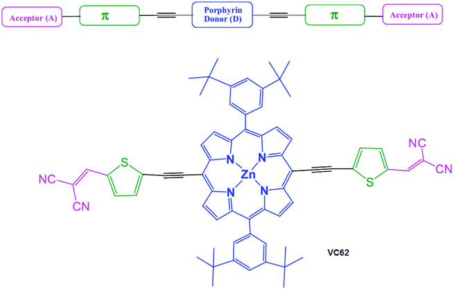
The target A–π-D–π-A porphyrin small molecule VC62 was achieved by a convergent synthesis strategy on the basis of the Sonagashira coupling reaction of 2-((5-bromothiophen-2-yl)methylene)malononitrile(3) with diacetylene porphyrin25 in the presence of dry THF, NEt3, Pd2(dba)3 and AsPh3. Knoevenagel condensation of malonodinitrile with bromothiophenaldehyde gave the intermediate (3). The synthetic route of VC62 is shown in Scheme 1. The important intermediates and the targeted small molecule VC62 were well characterized by 1H-NMR, 13C NMR, and ESI mass spectroscopy. In this manuscript, a new class of porphyrin small molecules is presented in which the porphyrin central unit contains an electron withdrawing dicyano as the end capped group. Introduction of the strongly electron donating group tert butyl of phenyl rings, attached at the meso-positions of the porphyrin core increases the electronic density on the porphyrin π-system and also improves solubility. The general architecture of the A–π-D–π-A small molecule and the molecular structure of VC62 is shown in Scheme 2.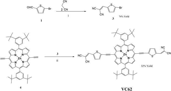 | ||
| Scheme 1 Synthetic route of VC62. Reaction conditions: (i) β-alanine, dichloroethane, ethanol, reflux, overnight, 74% yield. (ii) Pd2(dba)3, AsPh3, dry THF, NEt3, reflux 12 h, 32% yield. | ||
Photophysical and electrochemical properties
Fig. 1 shows the absorption spectra of VC62 in dilute THF solution and the thin film cast from the THF solvent. The VC62 exhibits a strong Soret band in the range of 400–540 nm with a peak at 482 nm and a moderate Q band in the range of 650–760 nm with a peak around 710 nm which is typical for ethynyl porphyrins.26 Compared to other porphyrin compounds, the Soret band of VC62 is red shifted and also broadened, and the Q band is also red shifted and intensified, probably due to the intermolecular charge transfer (ICT) between the donor and acceptor units. These spectral changes indicate an effective π-elongation through the porphyrin core, ethynyl and di-cyanovinyl substituted thiophene and better conjugation for VC62.27 The absorption spectrum of VC62 in thin film showed a red shift of 15 nm at the Q band region, which is attributed to the strong intermolecular interaction in the solid state. The optical bandgap of the VC62 is estimated from the onset of the absorption spectrum in thin film and is about 1.58 eV. This porphyrin molecule exhibits high mobilities and wide absorption from 400 to 800 nm with high absorption coefficients owing to the efficient conjugation in the backbone structure and intramolecular charge transfer (ICT) between the terminal acceptor units and the central donor building blocks.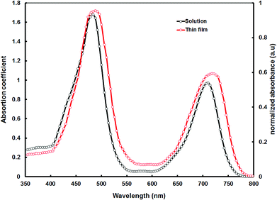 | ||
| Fig. 1 Optical absorption spectra of porphyrin VC62 in THF solution and thin film cast from the THF solvent. | ||
The HOMO and LUMO energy levels were determined by the cyclic voltammetry method with a film on a platinum wire as the working electrode in 0.1 M tetrabutylammonium hexafluorphosphate in THF at a potential scan rate of 10 mV s−1, and a platinum mesh as the counter electrode. The reference electrode was the silver calomel electrode (saturated KCl). The onset oxidation (Eoxonset) and reduction (Eredonset) potentials of VC62 were 1.04 V and −0.74 V vs. the saturated calomel electrode, respectively, from which the HOMO and LUMO energy levels were estimated using empirical expressions of EHOMO = −q(Eoxonset + 4.40) eV and ELUMO = −q(Eredonset + 4.40) eV, respectively. The estimated values of HOMO and LUMO levels of VC62 are −5.44 eV and −3.66 eV, respectively. The HOMO–LUMO gap estimated from the cyclic voltammetry is higher than the optical bandgap, which is a common feature in the organic semiconductors. The LUMO gap and the HOMO gap between the VC62 porphyrin (donor) and PCBM (acceptor) are 0.64 eV and 0.36 eV, respectively, are large enough to guarantee efficient exciton dissociation at donor/acceptor interfaces that exist in the BHJ active layer.28 The deeper value of the HOMO level of VC62 is beneficial to achieve the high open circuit voltage.
Theoretical calculation
We have performed the theoretical study of the VC62 porphyrin within the framework of density functional theory (DFT) and time dependent density functional theory (TD-DFT). The initial geometry optimization calculations were performed employing the gradient corrected functional PBE29 of Perdew, Burke and Ernzerhof. The triple-ζ quality TZVP basis set was used for all the calculations.30 At this stage of calculations, to increase the computational efficiency (without loss in accuracy), the resolution of the identity method was used for the treatment of the two-electron integrals.31 The resulting structures were further optimized using the hybrid exchange–correlation functional B3LYP32 and the same basis set. Truhlar's meta-hybrid exchange–correlation functional M0633 was also used for both ground state and excited state calculations. Tight convergence criteria were placed for the SCF energy (up to 10−7 Eh) and the one-electron density (rms of the density matrix up to 10−8) as well as for the norm of the Cartesian gradient (residual forces both average and maximum smaller than 1.5 × 10⁻⁵ a.u.) and residual displacements (both average and maximum smaller than 6 × 10⁻⁵ a.u.). Solvent effects were included for tetrahydrofuran using the integral equation formalism variant of the Polarizable Continuum Model (IEFPCM), as implemented in the Gaussian package.34 TD-DFT excited state calculations have been performed to calculate the optical gap of the VC62 porphyrin using the same functionals and the basis set on the corresponding ground state structures. The UV/Vis spectra were calculated using the B3LYP and M06 functionals. The first round of geometry optimization was performed using the Turbomole package.35 All of the follow up calculations were performed using the Gaussian package.34For the geometry optimization of the porphyrin structure a few rotamers were examined as initial geometries. The final optimized structure is a true local (if not global) minimum, as determined by vibrational analysis, i.e. none of the vibrational modes had imaginary eigenfrequencies. The main porphyrin part of the VC62 structure is a co-planar with the thiophene and cyano groups. At the optimized geometry the benzene planes form dihedral angles with the plane of the main structure of 71.1° when solvent effects are accounted for THF, and 75.0° in the gas phase. We have calculated the HOMO and LUMO energy levels and the optical gaps, defined here as the energetically lowest allowed vertical electronic excitation, employing the PBE, M06, and B3LYP functionals. In Table 1, in addition to the frontier orbitals’ energy levels, we also provide the optical gap of the main contributions to the first excitation as well as the wavelength of the first excitation and of the excitations with the largest oscillator strengths. In addition to the B3LYLP functional we have also performed our calculations employing the M06 functional. The M06 meta-hybrid functional was chosen since it provides leveled performance over transition types.36,37 We provide results using all three functionals, which can additionally be used for comparison with the literature.
| HOMO (eV) | LUMO (eV) | HL (eV) | OG (eV) | λ 1st max (nm) | f | Main contributions | μ (D) | |
|---|---|---|---|---|---|---|---|---|
| a Values when solvent effects are taken into account for THF. | ||||||||
| PBE | −5.24 | −4.11 | 1.13 | 1.52 | 814 | 1.56 | H → L (95.7%) | 0.07 |
| B3LYP | −5.68 | −3.77 | 1.91 | 1.74 | 712/498/447/404/346 | 1.68 | H → L 95.4%; H−1 → L+2 (4.6%) | 0.07 |
| −5.51a | −3.67a | 1.84a | 1.60a | 775/504/456/415/355a | 2.11a | H → L (97.3%)a | 0.21a | |
| M06 | −5.86 | −3.64 | 2.22 | 1.78 | 697/485/471/430/394/333 | 1.49 | H → L (90.1%); H−1 → L+2 (7.2%) | 0.06 |
| −5.71a | −3.55a | 2.15a | 1.65a | 750/496/484/439/405a | 1.92a | H → L (93.9%); H−1 → L+2 (4.0%)a | 0.21a | |
The PBE functional underestimates both the HOMO–LUMO (HL) and the optical gaps, as expected. The optical gaps calculated using the hybrid B3LYP and meta-hybrid M06 functionals are practically the same with the later in better agreement with the experiment. In Table 1, we also provide the character of the first allowed excitations only for contributions larger than 4%. The first excitation, as calculated by each of the functionals, clearly exhibits a single-configuration character, with only marginal (if any) secondary contributions.
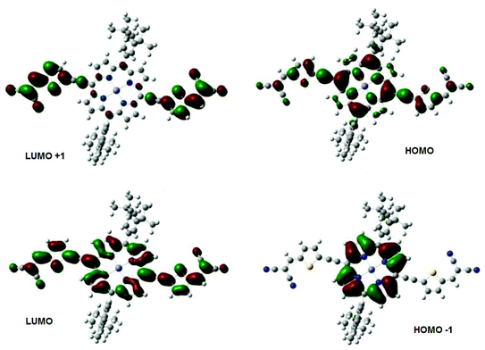
In Fig. 2, we have plotted the isosurfaces (isovalue = 0.02) of the HOMO and LUMO, as well as the next nearest frontier orbitals, for the porphyrin structure. Both the HOMO and LUMO extend over the main porphyrin structure and the cyano-thiophene moieties, with a varying level of delocalization. The HOMO−1 and LUMO+1 orbitals are localized on different parts of the porphyrin structure, specifically the former over the central porphyrin structure and the latter over the cyano-thiophene groups. To quantify the contributions of the moieties to the frontier orbitals we have calculated the total and partial density of states (PDOS). The PDOS for the porphyrin is shown in Fig. 3. We partitioned VC62 into the main porphyrin structure, the cyano-thiophene (CNTP), and the di-tert-butylbenzene (1,1-dimethylethylbenzene, BtMe) groups. The contribution of the CNTP and the main porphyrin structure to the HOMO is 35.9% and 61.0%, respectively, with only a 3.1% contribution from BtMe. The corresponding contributions to the LUMO are 53.4%, 45.7% and 0.8%, respectively. The first significant contributions (96.0%) from BtMe are noted at lower energies, around −7.2 eV, which corresponds to the HOMO−3 level. Accordingly, significant (above 5.2%) contributions of BtMe to unoccupied states are noted energetically much higher than LUMO, at −0.56 eV, which corresponds to the LUMO+9 level and to which it contributes 96.6%.
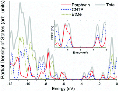 | ||
| Fig. 3 Total and partial density of states of the VC62 porphyrin (calculated using the M06 functional). | ||
In Fig. 4a we show the UV/Visual absorption spectra of the VC62 porphyrin calculated at the TD-DFT/M06 level of theory, both accounting for solvent effects for THF and in the gas phase. The spectra have been produced by convoluting Gaussian functions with HWHM = 0.18 eV centered at the excitation wave numbers. In Fig. 4b we also provide the corresponding spectra calculated using the B3LYP functional, which is in very good agreement with both using M06 and the experimental spectra. The Soret band (B band) and Q bands are noticeable, as expected for porphyrin structures. The wavelengths of the excitations with the largest oscillator strengths for bands are given in Table 1. Compared to the corresponding experimental spectrum the wave numbers are slightly larger, by about 10–20 nm for the Soret band and by about 35 nm for the Q band. The high intensity Soret band peaks are centered at 496 nm (2.50 eV), 484 nm (2.56 eV) and 439 nm (2.83 eV), which correspond to the 2nd, 3rd and 4th excited states (with non-negligible oscillator strengths). The B band peak is centered at 750 nm (1.65 eV).
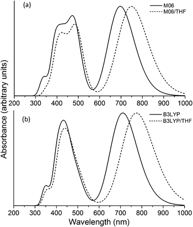 | ||
| Fig. 4 Theoretical absorption spectrum of the VC62 porphyrin calculated using (a) M06 and (b) B3LYP functional. | ||
Photovoltaic properties
In the organic BHJ solar cells using donor and acceptor materials, relative concentrations of these materials used in the active thin film significantly influences the photovoltaic performance, since there should be a balance between the absorbance and the charge transporting network in the active layer. When the concentration of acceptor material is too low, the electron transporting ability will be limited and with the higher amount of acceptor concentration, the absorbance and hole transport ability in the active layer will be decreased. BHJ active layers with mixtures of VC62 and PC71BM blended in THF in different weight ratios were tested, i.e. 1![[thin space (1/6-em)]](https://www.rsc.org/images/entities/char_2009.gif) :
:![[thin space (1/6-em)]](https://www.rsc.org/images/entities/char_2009.gif) 0.5, 1
0.5, 1![[thin space (1/6-em)]](https://www.rsc.org/images/entities/char_2009.gif) :
:![[thin space (1/6-em)]](https://www.rsc.org/images/entities/char_2009.gif) 1 and 1
1 and 1![[thin space (1/6-em)]](https://www.rsc.org/images/entities/char_2009.gif) :
:![[thin space (1/6-em)]](https://www.rsc.org/images/entities/char_2009.gif) 1.5. The optimum device performance was found for the 1
1.5. The optimum device performance was found for the 1![[thin space (1/6-em)]](https://www.rsc.org/images/entities/char_2009.gif) :
:![[thin space (1/6-em)]](https://www.rsc.org/images/entities/char_2009.gif) 1 ratio.
1 ratio.
The current–voltage (J–V) characteristics under AM1.5 (100 mW cm−2) simulated solar illumination of the BHJ solar cell with the optimized VC62![[thin space (1/6-em)]](https://www.rsc.org/images/entities/char_2009.gif) :
:![[thin space (1/6-em)]](https://www.rsc.org/images/entities/char_2009.gif) PC71BM (1
PC71BM (1![[thin space (1/6-em)]](https://www.rsc.org/images/entities/char_2009.gif) :
:![[thin space (1/6-em)]](https://www.rsc.org/images/entities/char_2009.gif) 1) processed from THF is shown in Fig. 5a and the photovoltaic parameters are summarized in Table 2. The device showed an overall PCE of 3.65% with Jsc = 8.82 mA cm−2, Voc = 0.94 V and FF = 0.44. The open circuit voltage of BHJ solar cells using VC62
1) processed from THF is shown in Fig. 5a and the photovoltaic parameters are summarized in Table 2. The device showed an overall PCE of 3.65% with Jsc = 8.82 mA cm−2, Voc = 0.94 V and FF = 0.44. The open circuit voltage of BHJ solar cells using VC62![[thin space (1/6-em)]](https://www.rsc.org/images/entities/char_2009.gif) :
:![[thin space (1/6-em)]](https://www.rsc.org/images/entities/char_2009.gif) PC71BM processed from THF is about 0.94 V, which is quite high, which may be due to the deeper HOMO level of VC62, since the Voc of the BHJ organic solar cells is directly related to the energy difference between the HOMO energy level of the donor and the LUMO energy level of the acceptor.
PC71BM processed from THF is about 0.94 V, which is quite high, which may be due to the deeper HOMO level of VC62, since the Voc of the BHJ organic solar cells is directly related to the energy difference between the HOMO energy level of the donor and the LUMO energy level of the acceptor.
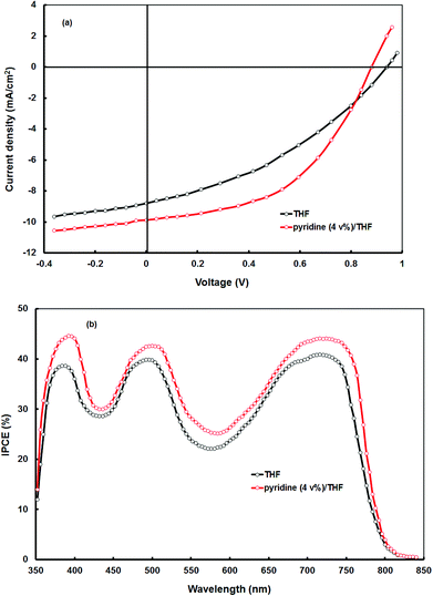 | ||
Fig. 5 (a) Current–voltage (J–V) characteristics under illumination and (b) IPCE spectra of the BHJ organic solar cells based on differently processed active layers of VC62![[thin space (1/6-em)]](https://www.rsc.org/images/entities/char_2009.gif) : :![[thin space (1/6-em)]](https://www.rsc.org/images/entities/char_2009.gif) PC71BM. PC71BM. | ||
![[thin space (1/6-em)]](https://www.rsc.org/images/entities/char_2009.gif) :
:![[thin space (1/6-em)]](https://www.rsc.org/images/entities/char_2009.gif) PC71BM in a 1
PC71BM in a 1![[thin space (1/6-em)]](https://www.rsc.org/images/entities/char_2009.gif) :
:![[thin space (1/6-em)]](https://www.rsc.org/images/entities/char_2009.gif) 1 weight ratio
1 weight ratio
| Active layer | J sc (mA cm−2) | V oc (V) | FF | PCE (%) |
|---|---|---|---|---|
VC62![[thin space (1/6-em)]](https://www.rsc.org/images/entities/char_2009.gif) : :![[thin space (1/6-em)]](https://www.rsc.org/images/entities/char_2009.gif) PC71BM (THF cast) PC71BM (THF cast) |
8.82 | 0.94 | 0.44 | 3.65 |
VC62![[thin space (1/6-em)]](https://www.rsc.org/images/entities/char_2009.gif) : :![[thin space (1/6-em)]](https://www.rsc.org/images/entities/char_2009.gif) PC71BM (pyridine–THF cast) PC71BM (pyridine–THF cast) |
10.64 | 0.88 | 0.56 | 5.24 |
The IPCE values of the solar cell were estimated from the following expression:
| IPCE(λ) = 1240 Jsc/λPin |
![[thin space (1/6-em)]](https://www.rsc.org/images/entities/char_2009.gif) :
:![[thin space (1/6-em)]](https://www.rsc.org/images/entities/char_2009.gif) PC71BM thin film (as shown in Fig. 1), indicating that both VC62 and PC71BM contribute to the exciton generation after the absorption of photons by the blend thin film. The IPCE values in both the Soret band and the Q band are similar which means that despite the different absorptions both the electronic transitions are capable of transformation with the same efficiency of photons to electrons.
PC71BM thin film (as shown in Fig. 1), indicating that both VC62 and PC71BM contribute to the exciton generation after the absorption of photons by the blend thin film. The IPCE values in both the Soret band and the Q band are similar which means that despite the different absorptions both the electronic transitions are capable of transformation with the same efficiency of photons to electrons.
The overall PCE of the organic solar cell VC62![[thin space (1/6-em)]](https://www.rsc.org/images/entities/char_2009.gif) :
:![[thin space (1/6-em)]](https://www.rsc.org/images/entities/char_2009.gif) PC71BM processed with THF solvent is smaller as compared to the latest development in the polymers and small molecules as a donor with almost the same configuration. Although, the Voc of the present device is quite high (Voc = 0.94 V), its poor performance can be attributed to the low values of Jsc and FF. These two parameters are directly related to the light harvesting efficiency of the BHJ active layer, film morphology, charge transport and their collection on the respective electrodes. In most of the organic BHJ solar cells, the Jsc value is related to both electron and hole transport efficiencies within the active layer. The electron mobility is usually much higher than that of hole mobility, resulting in unbalanced charge transport.38 Moreover, the well-defined nanomorphology of the BHJ active layer within the range of the exciton diffusion length is necessary for the efficient exciton dissociation.39
PC71BM processed with THF solvent is smaller as compared to the latest development in the polymers and small molecules as a donor with almost the same configuration. Although, the Voc of the present device is quite high (Voc = 0.94 V), its poor performance can be attributed to the low values of Jsc and FF. These two parameters are directly related to the light harvesting efficiency of the BHJ active layer, film morphology, charge transport and their collection on the respective electrodes. In most of the organic BHJ solar cells, the Jsc value is related to both electron and hole transport efficiencies within the active layer. The electron mobility is usually much higher than that of hole mobility, resulting in unbalanced charge transport.38 Moreover, the well-defined nanomorphology of the BHJ active layer within the range of the exciton diffusion length is necessary for the efficient exciton dissociation.39
It was reported that the morphology of the BHJ active layers using either polymers or small molecules can be improved by appropriate treatment methodologies which include thermal annealing40 and solvent additives.41 Recently, the solvent additive has been also adopted for BHJ thin film using porphyrins as the donor and fullerene derivatives as the acceptor and the PCE has been significantly improved.19 We have tried to improve the performance of the BHJ organic solar cells based on VC62![[thin space (1/6-em)]](https://www.rsc.org/images/entities/char_2009.gif) :
:![[thin space (1/6-em)]](https://www.rsc.org/images/entities/char_2009.gif) PC71BM (1
PC71BM (1![[thin space (1/6-em)]](https://www.rsc.org/images/entities/char_2009.gif) :
:![[thin space (1/6-em)]](https://www.rsc.org/images/entities/char_2009.gif) 2) using the solvent additive method. We have used pyridine as the solvent additive for the deposition of the VC62
2) using the solvent additive method. We have used pyridine as the solvent additive for the deposition of the VC62![[thin space (1/6-em)]](https://www.rsc.org/images/entities/char_2009.gif) :
:![[thin space (1/6-em)]](https://www.rsc.org/images/entities/char_2009.gif) PC71BM active layer. The current–voltage characteristics of the BHJ solar cell processed with a 4% pyridine–THF solvent is shown in Fig. 5a and the corresponding photovoltaic parameters are displayed in Table 2. We can see that the Jsc (10.64 mA cm−2) and FF (0.64) have significantly improved, however, Voc decreased from 0.94 V to 0.88 V, resulting in an overall PCE of 5.24%.
PC71BM active layer. The current–voltage characteristics of the BHJ solar cell processed with a 4% pyridine–THF solvent is shown in Fig. 5a and the corresponding photovoltaic parameters are displayed in Table 2. We can see that the Jsc (10.64 mA cm−2) and FF (0.64) have significantly improved, however, Voc decreased from 0.94 V to 0.88 V, resulting in an overall PCE of 5.24%.
The enhancement in the PCE is mainly attributed to the significant increase in values of Jsc and FF. The improvement in the value of Jsc can be ascribed to the enhancement in the values of IPCE of the device processed with the pyridine–THF solvent. As shown in Fig. 5b the solar cell with the active layer processed with pyridine–THF exhibits higher values of IPCE and a broader IPCE response as compared to the solar cell with the active layer processed with THF only. The Jsc value and the IPCE response of a solar cell are related by the expression:
In an organic BHJ solar cell, the IPCE is represented by the product of the efficiencies of four sequential steps for charge generation:
| IPCE = ηAηEDηCTηCC |
![[thin space (1/6-em)]](https://www.rsc.org/images/entities/char_2009.gif) :
:![[thin space (1/6-em)]](https://www.rsc.org/images/entities/char_2009.gif) PC71BM blend cast from the pyridine–THF is shown in Fig. 6. As shown in this figure, the absorption peak corresponds to the longer wavelength region is red-shifted from 715 nm to 730 nm and also the absorption coefficient is also increased, as compared to that for the THF cast blend. Moreover, the blend film also showed a new shoulder peak at 756 nm, which is attributed to the formation of the vibronic crystalline structure42 and could be beneficial to the higher hole mobility. This absorption characteristic of the film indicates that the absorption efficiency of the solar cell has been increased and yielded high IPCE values and Jsc.43
PC71BM blend cast from the pyridine–THF is shown in Fig. 6. As shown in this figure, the absorption peak corresponds to the longer wavelength region is red-shifted from 715 nm to 730 nm and also the absorption coefficient is also increased, as compared to that for the THF cast blend. Moreover, the blend film also showed a new shoulder peak at 756 nm, which is attributed to the formation of the vibronic crystalline structure42 and could be beneficial to the higher hole mobility. This absorption characteristic of the film indicates that the absorption efficiency of the solar cell has been increased and yielded high IPCE values and Jsc.43
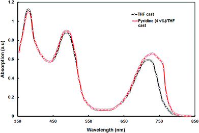 | ||
Fig. 6 Optical absorption spectra of the VC62![[thin space (1/6-em)]](https://www.rsc.org/images/entities/char_2009.gif) : :![[thin space (1/6-em)]](https://www.rsc.org/images/entities/char_2009.gif) PC71BM thin films cast from THF and pyridine–THF solvents. PC71BM thin films cast from THF and pyridine–THF solvents. | ||
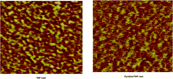
The factor that also contributes to the increased PCE of the later device is the change in the nanomorphology of the active layer. For the high performance of the BHJ organic solar cell, nanoscale phase separation of the active layer is one of the morphological requirements, i.e. the domain size must be in the range of 10–15 nm, which enables a large interfacial area for exciton dissociation. The morphology of the active layer was examined by the atomic force microscopy (AFM) technique in tapping mode. The AFM images of the BHJ active layer of VC62![[thin space (1/6-em)]](https://www.rsc.org/images/entities/char_2009.gif) :
:![[thin space (1/6-em)]](https://www.rsc.org/images/entities/char_2009.gif) PC71BM (1
PC71BM (1![[thin space (1/6-em)]](https://www.rsc.org/images/entities/char_2009.gif) :
:![[thin space (1/6-em)]](https://www.rsc.org/images/entities/char_2009.gif) 2) processed with THF and pyridine–THF are shown in Fig. 7. The film cast from THF showed a smooth surface with a root mean square (rms) roughness of 3.45 nm and domain sizes estimated by the cross section profiles are in the range of 40–50 nm, while the domain sizes reduced to 15–20 nm with a surface roughness of 1.45 nm, when the film is cast from the pyridine–THF solvent. The reduced domain sizes are beneficial for increasing the D–A interfacial area for exciton dissociation to charge transfer efficiency and charge collection efficiency, resulting in enhanced values of Jsc and PCE.44
2) processed with THF and pyridine–THF are shown in Fig. 7. The film cast from THF showed a smooth surface with a root mean square (rms) roughness of 3.45 nm and domain sizes estimated by the cross section profiles are in the range of 40–50 nm, while the domain sizes reduced to 15–20 nm with a surface roughness of 1.45 nm, when the film is cast from the pyridine–THF solvent. The reduced domain sizes are beneficial for increasing the D–A interfacial area for exciton dissociation to charge transfer efficiency and charge collection efficiency, resulting in enhanced values of Jsc and PCE.44
For efficient BHJ organic solar cells, the electron and hole mobilities in the active layer also play an important role, as these should be balanced in order to achieve an efficient charge transport. The hole and electron mobilities in the VC62![[thin space (1/6-em)]](https://www.rsc.org/images/entities/char_2009.gif) :
:![[thin space (1/6-em)]](https://www.rsc.org/images/entities/char_2009.gif) PC71BM blend films were estimated from the hole only devices and electron only devices, respectively, prepared from THF and pyridine–THF processed films, by means of space charge limited current (SCLC) measurements45 and the J–V curves are shown in Fig. 8a and 8b. The hole mobility and electron mobility are 8.34 × 10⁻⁵ cm2 V−1 s−1 and 2.32 × 10⁻⁴ cm2 V−1 s−1, respectively, for devices processed with pyridine–THF, and the ratio of electron to hole mobility is much smaller than the devices fabricated with THF only (hole and electron mobilities are 5.62 × 10⁻⁶ cm2 V−1 s−1 and 2.45 × 10⁻⁴ cm2 V−1 s−1, respectively). Therefore, the addition of pyridine additive improves the hole mobility, but slightly lowers the electron mobility, leading to a more balanced charge transport.
PC71BM blend films were estimated from the hole only devices and electron only devices, respectively, prepared from THF and pyridine–THF processed films, by means of space charge limited current (SCLC) measurements45 and the J–V curves are shown in Fig. 8a and 8b. The hole mobility and electron mobility are 8.34 × 10⁻⁵ cm2 V−1 s−1 and 2.32 × 10⁻⁴ cm2 V−1 s−1, respectively, for devices processed with pyridine–THF, and the ratio of electron to hole mobility is much smaller than the devices fabricated with THF only (hole and electron mobilities are 5.62 × 10⁻⁶ cm2 V−1 s−1 and 2.45 × 10⁻⁴ cm2 V−1 s−1, respectively). Therefore, the addition of pyridine additive improves the hole mobility, but slightly lowers the electron mobility, leading to a more balanced charge transport.
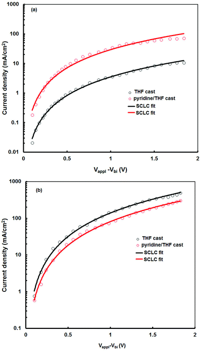 | ||
Fig. 8 Current–voltage (J–V) characteristics in the dark for (a) hole-only and (b) electron-only solar cell devices, using two differently processed VC62![[thin space (1/6-em)]](https://www.rsc.org/images/entities/char_2009.gif) : :![[thin space (1/6-em)]](https://www.rsc.org/images/entities/char_2009.gif) PC71BM active layer blends. PC71BM active layer blends. | ||
Conclusions
In summary, we have synthesized an A–D–A porphyrin VC62 with a low bandgap (∼1.58 eV) and, moreover, we investigated its optical and electrochemical properties (both theoretically and experimentally). The photophysical and electrochemical investigations of VC62 and PC71BM films probes that the VC62![[thin space (1/6-em)]](https://www.rsc.org/images/entities/char_2009.gif) :
:![[thin space (1/6-em)]](https://www.rsc.org/images/entities/char_2009.gif) PC71BM blend can effectively harvest photons from the visible to near infrared regions of the solar spectrum and transfer the electrons to PC71BM molecules, resulting in a photovoltaic effect. The solution processed BHJ solar cell based on VC62
PC71BM blend can effectively harvest photons from the visible to near infrared regions of the solar spectrum and transfer the electrons to PC71BM molecules, resulting in a photovoltaic effect. The solution processed BHJ solar cell based on VC62![[thin space (1/6-em)]](https://www.rsc.org/images/entities/char_2009.gif) :
:![[thin space (1/6-em)]](https://www.rsc.org/images/entities/char_2009.gif) PC71BM processed from the THF solvent displayed a PCE of 3.65%. In order to improve the PCE of this solar cell, the VC62
PC71BM processed from the THF solvent displayed a PCE of 3.65%. In order to improve the PCE of this solar cell, the VC62![[thin space (1/6-em)]](https://www.rsc.org/images/entities/char_2009.gif) :
:![[thin space (1/6-em)]](https://www.rsc.org/images/entities/char_2009.gif) PC71BM layer was spin cast from a mixture of 4 vol% pyridine–THF and the device showed a PCE of 5.24%, attributed to the enhancement in the Jsc and FF. This is a result of the enhanced IPCE response and reduced domain sizes in the active layer, which leads to a more balanced charge transport, and enhanced hole mobility in the BHJ active layer.
PC71BM layer was spin cast from a mixture of 4 vol% pyridine–THF and the device showed a PCE of 5.24%, attributed to the enhancement in the Jsc and FF. This is a result of the enhanced IPCE response and reduced domain sizes in the active layer, which leads to a more balanced charge transport, and enhanced hole mobility in the BHJ active layer.
Acknowledgements
EP would like to thank MINECO for the project CTQ2013-47183-R and the support through Severo Ochoa Excellence Accreditation 2014-2018(SEV-2013-0319). We are also thankful to the Material Science Research Laboratory, MNIT, Jaipur, Rajasthan, for providing the characterization facilities.References
- (a) J. Chen and Y. Cao, Acc. Chem. Res., 2009, 42, 1709–1718 CrossRef CAS PubMed; (b) Y. J. Cheng, s. H. Yang and C. S. Hsu, Chem. Rev., 2009, 109, 5868–5923 CrossRef CAS PubMed; (c) G. Li, R. Zhu and Y. Yang, Nat. Photonics, 2012, 6, 153–161 CrossRef CAS; (d) Y. Li, Acc. Chem. Res., 2012, 45, 723–733 CrossRef CAS PubMed.
- (a) J. You, L. Dou, K. Yoshimura, T. Kato, K. Ohya, T. Moriarty, K. Emery, C. C. Chen, J. Gao, G. Li and Y. Yang, Nat. Commun., 2013, 4, 1446 CrossRef PubMed; (b) Z. C. He, C. M. Zhong, X. Huang, W. Y. Wong, H. B. Wu, L. W. Chen, S. J. Su and Y. Cao, Adv. Mater., 2011, 23, 4636–4643 CrossRef CAS PubMed; (c) Z. C. He, C. M. Zhong, S. J. Su, M. Xu, H. B. Wu and Y. Cao, Nat. Photonics, 2012, 6, 591–595 Search PubMed; (d) W. Y. Wong and C. L. Ho, Acc. Chem. Res., 2010, 43, 1246–1256 CrossRef CAS PubMed; (e) M. Wang, X. W. Hu, P. Liu, W. Li, X. Gong, F. Huang and Y. Cao, J. Am. Chem. Soc., 2011, 133, 9638–9641 CrossRef CAS PubMed.
- A. Salleo, R. J. Kline and D. M. Delongchamp, et al. , Adv. Mater., 2010, 22, 3812–3838 CrossRef CAS PubMed.
- (a) Y. Lin, Y. Li and X. Zhan, Chem. Soc. Rev., 2012, 41, 4245–4272 RSC; (b) Y. Chen, X. Wan and G. Long, Acc. Chem. Res., 2013, 46, 2645–2655 CrossRef CAS PubMed.
- (a) H. Shang, H. Fan, Y. Liu, W. Hu, Y. Li and X. Zhan, Adv. Mater., 2011, 23, 1554–1557 CrossRef CAS PubMed; (b) Q. Shi, P. Cheng, Y. Li and X. Zhan, Adv. Energy Mater., 2012, 2, 63–67 CrossRef CAS; (c) T. Bura, N. Leclerc, R. Bechara, P. Lévêque, T. Heiser and R. Ziessel, Adv. Energy Mater., 2013, 3, 1118–1124 CrossRef CAS; (d) Y. Liu, Y. M. Yang, C. C. Chen, Q. Chen, L. Dou, Z. Hong, G. Li and Y. Yang, Adv. Mater., 2013, 25, 4657–4662 CrossRef CAS PubMed; (e) Y. Sun, G. C. Welch, W. L. Leong, C. J. Takacs, G. C. Bazan and A. J. Heeger, Nat. Mater., 2011, 11, 44–48 CrossRef PubMed; (f) T. S. van der Poll, J. A. Love, T. Q. Nguyen and G. C. Bazan, Adv. Mater., 2012, 24, 3646–3649 CrossRef CAS PubMed.
- (a) V. Gupta, A. K. K. Kyaw, D. H. Wang, S. Chand, G. C. Bazan and A. J. Heeger, Sci. Rep., 2013, 3, 1965 Search PubMed; (b) Y. Liu, C. C. Chen, Z. Hong, J. Gao, Y. Yang, H. Zhou, L. Dou, G. Li and Y. Yang, Sci. Rep., 2013, 3, 3356 Search PubMed.
- http://www.heliatek.com/newscenter/latest_news/neuer-weltrekord-furorganische-solarzellen-heliatek-behauptet-sich-mit-12-zelleffizienz-als-technologiefuhrer/?lang=enSmall molecule organic solar cells by Heliatek/IAPP with a certified efficiency of 12.0%, press release, January 2013; http://www.heliatek.com (accessed February 2013).
- (a) C. W. Lee, H. P. Lu, C. M. Lan, Y. L. Huang, Y. R. Liang, W. N. Yen, Y. C. Liu, Y. S. Lin, E. W. G. Diau and C. Y. Yeh, Chem. – Eur. J., 2009, 15, 1403 CrossRef CAS PubMed; (b) C. L. Mai, W. K. Huang, H. P. Lu, C. W. Lee, C. L. Chiu, Y. R. Liang, E. W. G. Diau and C. Y. Yeh, Chem. Commun., 2010, 46, 809 RSC.
- (a) A. Kay and M. Grätzel, J. Phys. Chem., 1993, 97, 6272 CrossRef CAS; (b) M. S. Kang, J. B. Oh, K. D. Seo, H. K. Kim, J. Park, K. Kim and N. G. Park, J. Porphyrins Phthalocyanines, 2009, 13, 798 CrossRef CAS.
- L.-L. Li and E. W.-G. Diau, Chem. Soc. Rev., 2013, 42, 291–304 RSC.
- (a) N. M. Reddy, T. Y. Pan, Y. C. Rajan, B. C. Guo, C. M. Lan, E. W. G. Diau and C. Y. Yeh, Phys. Chem. Chem. Phys., 2013, 15, 8409 RSC; (b) S. H. Kang, I. T. Choi, M. S. Kang, Y. K. Eom, M. J. Ju, J. Y. Hong, H. S. Kang and H. K. Kim, J. Mater. Chem. A, 2013, 1, 3977–3982 RSC; (c) S. Mathew, A. Yella, P. Gao, R. Humphry-Baker, B. F. E. Curchod, N. Ashari-Astani, I. Tavernelli, U. Rothlisberger, M. K. Nazeeruddin and M. Grätzel, Nat. Chem., 2014, 6, 242 CrossRef CAS PubMed; (d) K. Ladomenou, T. N. Kitsopoulos, G. D. Sharma and A. G. Coutsolelos, RSC Adv., 2014, 4, 21379 RSC.
- A. Yella, H. W. Lee, H. N. Tsao, C. Yi, A. K. Chandiran, M. K. Nazeeruddin, E. W. G. Diau, C. Y. Yeh, S. M. Zakeeruddin and M. Grätzel, Science, 2011, 334, 629–634 CrossRef CAS PubMed.
- (a) Y. Shao and Y. Yang, Adv. Mater., 2005, 17, 2841 CrossRef CAS; (b) Z.-X. Xu, V. A. L. Roy, Z.-T. Liu and C. S. Lee, Appl. Phys. Lett., 2010, 97, 163301 CrossRef PubMed.
- (a) Y. Matsuo, Y. Sato, T. Niinomi, I. Soga, H. Tanaka and E. Nakamura, J. Am. Chem. Soc., 2009, 131, 16048 CrossRef CAS PubMed; (b) S. Ito, T. Murashima, H. Uno and N. Ono, Chem. Commun., 1998, 1661 RSC; (c) S. Aramaki, Y. Sakai and N. Ono, Appl. Phys. Lett., 2004, 84, 2085 CrossRef CAS PubMed.
- (a) J. Hatano, N. Obata, S. Yamaguchi, T. Yasuda and Y. Matsuo, J. Mater. Chem., 2012, 22, 19258 RSC.
- Y. Huang, L. Li, X. Peng, J. Peng and Y. Cao, J. Mater. Chem., 2012, 22, 21841 RSC.
- L. Li, Y. Huang, J. Peng, Y. Cao and X. Peng, J. Mater. Chem. A, 2013, 1, 2144–2150 CAS.
- G. D. Sharma, D. Daphnomili, S. Biswas and A. G. Coutsolelos, Org. Electron., 2013, 14, 1811 CrossRef CAS PubMed.
- H. Qin, L. Li, F. Guo, S. Su, J. Peng, Y. Cao and X. Peng, Energy Environ. Sci., 2014, 7, 1397–1401 CAS.
- (a) N. Robertson, Angew. Chem., Int. Ed., 2006, 45, 2338 CrossRef CAS PubMed; (b) Y. Ooyama and Y. Harima, Eur. J. Org. Chem., 2009, 2903–2934 CrossRef CAS; (c) A. Mishra, M. K. R. Fischer and P. Bäuerle, Angew. Chem., Int. Ed., 2009, 48, 2474–2499 CrossRef CAS PubMed; (d) Z. J. Ning, Y. Fu and H. Tian, Energy Environ. Sci., 2010, 3, 1170 RSC.
- V. A. Nuay, D.-H. Kim, S.-H. Lee and J. J. Ko, Bull. Korean Chem. Soc., 2009, 30, 2871 CrossRef CAS.
- Y. Liu, N. Xiang, X. Feng, P. Shen, W. Zhou, C. Weng, B. Zhao and S. Tan, Chem. Commun., 2009, 2499 RSC.
- (a) R. Fitzner, C. Elschner, M. Weil, C. Uhrich, C. Körner, M. Riede, K. Leo, M. Pfeiffer, E. Reinold, E. M. Osteritz and P. Bäuerle, Adv. Mater., 2012, 24, 675 CrossRef CAS PubMed; (b) A. Gupta, A. Ali, A. Bilic, M. Gao, K. Hegedus, B. Singh, S. E. Watkins, G. J. Wilson, U. Bach and R. A. Evans, Chem. Commun., 2012, 48, 1889 RSC; (c) Y. Z. Lin, Z. G. Zhang, H. T. Bai, Y. F. Li and X. W. Zhan, Chem. Commun., 2012, 48, 9655 RSC; (d) S. H. Zeng, L. X. Yin, C. Y. Ji, X. Y. Jiang, K. C. Li, Y. Q. Li and Y. Wang, Chem. Commun., 2012, 48, 10627 RSC; (e) M. Charlotte, S. Gurunathan, A. Magali, K. Václav, S. Jiří, F. Pierre and R. Jean, J. Org. Chem., 2012, 77, 2041 CrossRef PubMed; (f) N. F. Montcada, B. Pelado, A. Viterisi, J. Albero, J. Coro, P. de la Cruz, F. Langa and E. Palomares, Org. Electron., 2013, 14, 2826–2832 CrossRef CAS PubMed.
- J. Zhou, Y. Zuo, X. Wan, G. Long, Q. Zhang, W. Ni, Y. Liu, Z. Li, G. He, C. Li, B. Kan and Y. Chen, J. Am. Chem. Soc., 2013, 135, 8484 CrossRef CAS PubMed.
- M. J. Plater, S. Aiken and G. Bourhill, Tetrahedron, 2002, 58, 2405 CrossRef CAS.
- T. E. O. Screen, K. B. Lawton, G. S. Wilson, N. Dolney, R. Ispasoiu, T. Goodson III, S. J. Martin, D. D. C. Bradley and H. L. Anderson, J. Mater. Chem., 2001, 11, 312 RSC.
- (a) H. Imahori, T. Umeyama and S. Ito, Acc. Chem. Res., 2009, 42, 1809 CrossRef CAS PubMed; (b) V. S.-Y. Lin, S. G. DiMagno and M. J. Therien, Science, 1994, 264, 1105 CAS; (c) C. Y. Lee, C. She, N. C. Jeong and J. T. Hupp, Chem. Commun., 2010, 46, 6090 RSC.
- C. J. Brabec, C. Winder, N. S. Sariciftci, J. C. Hummelen, A. Dhanabalan, P. A. van Hal and R. A. J. Janssen, Adv. Funct. Mater., 2002, 12, 709 CrossRef CAS.
- J. P. Perdew, K. Burke and M. Ernzerhof, Phys. Rev. Lett., 1996, 77, 3865 CrossRef CAS.
- A. Schäfer, C. Huber and R. J. Ahlrichs, Chem. Phys., 1994, 100, 5829 Search PubMed.
- K. Eichkorn, O. Treutler, H. Öhm, M. Häser and R. Ahlrichs, Chem. Phys. Lett., 1995, 240, 283 CrossRef CAS.
- (a) A. D. Becke, J. Chem. Phys., 1993, 98, 5648 CrossRef CAS PubMed; (b) C. Lee, W. Yang and R. G. Parr, Phys. Rev. B: Condens. Matter, 1988, 37, 785 CrossRef CAS.
- Y. Zhao and D. G. Truhlar, Theor. Chem. Acc., 2008, 120, 215 CrossRef CAS.
- M. J. Frisch, G. W. Trucks, H. B. Schlegel, G. E. Scuseria, M. A. Robb, J. R. Cheeseman, G. Scalmani, V. Barone, B. Mennucci, G. A. Petersson, H. Nakatsuji, M. Caricato, X. Li, H. P. Hratchian, A. F. Izmaylov, J. Bloino, G. Zheng, J. L. Sonnenberg, M. Hada, M. Ehara, K. Toyota, R. Fukuda, J. Hasegawa, M. Ishida, T. Nakajima, Y. Honda, O. Kitao, H. Nakai, T. Vreven, J. A. Montgomery Jr., J. E. Peralta, F. Ogliaro, M. Bearpark, J. J. Heyd, E. Brothers, K. N. Kudin, V. N. Staroverov, R. Kobayashi, J. Normand, K. Raghavachari, A. Rendell, J. C. Burant, S. S. Iyengar, J. Tomasi, M. Cossi, N. Rega, J. M. Millam, M. Klene, J. E. Knox, J. B. Cross, V. Bakken, C. Adamo, J. Jaramillo, R. Gomperts, R. E. Stratmann, O. Yazyev, A. J. Austin, R. Cammi, C. Pomelli, J. W. Ochterski, R. L. Martin, K. Morokuma, V. G. Zakrzewski, G. A. Voth, P. Salvador, J. J. Dannenberg, S. Dapprich, A. D. Daniels, O. Farkas, J. B. Foresman, J. V. Ortiz, J. Cioslowski and D. J. Fox, Gaussian 03, revision C.01, Gaussian, Inc., Wallingford CT, 2004 Search PubMed.
- TURBOMOLE (version 5.6), Universitat Karlsruhe, 2000 Search PubMed.
- D. Jacquemin, E. A. Perpète, I. Ciofini, C. Adamo, R. Valero, Y. Zhao and D. G. Truhlar, J. Chem. Theory Comput., 2010, 6, 2071 CrossRef CAS.
- S. Mathew, A. Yella, P. Gao, R. Humphry-Baker, F. E. Curchod, N. Ashari-Astani, I. Tavernelli, U. Rothlisberger, M. K. Nazeeruddin and M. Gratzel, Nat. Chem., 2014, 6, 242 CrossRef CAS PubMed.
- V. D. Mihailetchi, H. Xie, B. de Boer, L. J. A. Koster and P. W. M. Blom, Adv. Funct. Mater., 2006, 16, 699 CrossRef CAS.
- Y. Li, Acc. Chem. Res., 2012, 45, 723 CrossRef CAS PubMed.
- Z. Yi, W. Ni, Q. Zhang, M. Li, B. Kan, X. Wan and Y. Chen, J. Mater. Chem. C, 2014, 2, 7247 RSC.
- (a) Y. Chen, X. Wan and G. Long, Acc. Chem. Res., 2013, 46, 2645 CrossRef CAS PubMed; (b) J. E. Coughlin, Z. B. Henson, G. C. Welch and G. C. Bazan, Acc. Chem. Res., 2013, 47, 257 CrossRef PubMed.
- (a) F.-C. Chen, H.-C. Tseng and C.-J. Ko, Appl. Phys. Lett., 2008, 92, 103316 CrossRef PubMed; (b) J. Hou, H. Y. Chen, S. Zhang, G. Li and Y. Yang, J. Am. Chem. Soc., 2008, 130, 16144 CrossRef CAS PubMed.
- J. Peet, J. Y. Kim, N. E. Coates, W. L. Ma, D. Moses, A. J. Heeger and G. C. Bazan, Nat. Mater., 2007, 6, 497 CrossRef CAS PubMed.
- (a) W. L. Leong, G. C. Welch, J. Seifter, J. H. Seo, G. C. Bazan and A. J. Heeger, Adv. Energy Mater., 2013, 3, 356 CrossRef CAS; (b) M.-S. Su, C.-Y. Kuo, M.-C. Yuan, U. S. Jeng, C.-J. Su and K.-H. Wei, Adv. Mater., 2011, 23, 3315 CrossRef CAS PubMed; (c) C. H. Woo, P. M. Beaujuge, T. W. Holcombe, O. P. Lee and J. M. J. Frechet, J. Am. Chem. Soc., 2010, 132, 15547 CrossRef CAS PubMed.
- G. Malliaras, J. Salem, P. Brock and C. Scott, Phys. Rev. B: Condens. Matter Mater. Phys., 1998, 58, 13411 CrossRef.
| This journal is © The Royal Society of Chemistry 2015 |

