 Open Access Article
Incorporation of organic crystals into the interspace of oriented nanocrystals: morphologies and properties†
Yurika
Munekawa
,
Yuya
Oaki
*,
Kosuke
Sato
and
Hiroaki
Imai
*
Department of Applied Chemistry, Faculty of Science and Technology, Keio University, 3-14-1 Hiyoshi, Kohoku-ku, Yokohama 223-8522, Japan. E-mail: oakiyuya@applc.keio.ac.jp; hiroaki@applc.keio.ac.jp
First published on 3rd December 2014
Abstract
Oriented nanocrystals, as seen in biominerals, have both the macroscopic hierarchical morphologies and the nanoscale interspace among the unit crystals. Here we studied the incorporation effects of the specific interspace in the oriented nanocrystals on the morphologies, properties, and applications of organic crystals. Organic crystals, such as 9-vinylcarbazole (VCz), azobenzene (AB), and pyrene (PY), were introduced into the specific interspace of oriented nanocrystals from the melts. The morphologies and properties of the incorporated organic crystals were systematically studied in these model cases. The incorporation of the organic crystals provided the composites with the original oriented nanocrystals. The incorporated organic crystals formed the single-crystalline structures even in the nanoscale interspace. The melts of the organic compounds were crystallized and grown in the interspace of the original materials. The incorporated organic crystals showed the specific phase transition behavior. The freezing points of the organic crystals were raised by the incorporation into the nanospace while the melting points were not changed. The hierarchical morphologies of the organic crystals were obtained after the dissolution of the original materials. The hierarchical morphologies of the original materials were replicated to the organic crystals. The incorporated organic crystal was polymerized without deformation of the hierarchical morphologies. The hierarchical polymer can be applied to the donor material for the generation of a larger amount of the charge-transfer complex with the acceptor molecule than the commercial polymer microparticles. The present work shows the potential use of the nanoscale interspace generated in the oriented nanocrystals.
Introduction
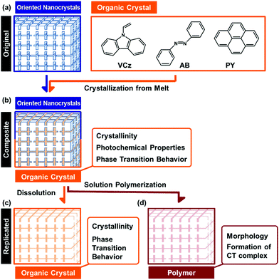
Organized structures of oriented nanocrystals have attracted much interest in recent years.1,2 The nanoscale interspace between the unit crystals can incorporate guest materials.3,4 Here we incorporated a couple of organic crystals into the interspace of the oriented nanocrystal. The incorporation effects of the interspace on the morphologies and properties of the incorporated organic crystals were systematically studied for an improved understanding of the nanoscale interspace. Recent reports have shown a variety of the oriented nanocrystals, such as mesocrystals and bridged nanocrystals, found in biominerals and biomimetic materials.5 Organization of nanocrystals as the building blocks generates a variety of hierarchical morphologies from the nanoscopic to the macroscopic scale. The syntheses, formation mechanisms, and applications of oriented nanocrystals have been widely studied in recent reports.6–15 For example, oriented nanocrystals were applied to catalysts and electrode materials with improved performances.12–14 In a review paper,1g Zhou and O'Brien indicated that the high performances are mainly ascribed to the contribution of the unit nanocrystals. Our recent challenge has been to exhibit the nature of the oriented nanocrystals as organized structures. We have studied the interspace of the unit crystals for incorporation of organic molecules.3,4 The incorporation and polymerization of monomers in the nanospace direct the replication of the hierarchically organized morphologies from the original materials to the polymers.4 The morphology replication is ascribed to not only the properties of each nanocrystal but also those of the organized structures. The organized structures of the oriented nanocrystals provide both the nanospace and the macroscopic morphologies. Our intention here is to study the incorporation effects of the nanospace on the morphologies, properties, and applications of organic crystals. The organic crystals were incorporated into the interspace of the oriented nanocrystals from the melts (Fig. 1a and b). The hierarchical morphologies of the original materials were replicated to the organic crystals (Fig. 1b and c). Interestingly, the incorporated organic crystals formed the single crystalline structures even in the nanospace of the original materials. The specific phase-transition behavior was observed on the incorporated organic crystals. Materials with nanospace have been studied in recent decades, such as zeolites, porous materials, layered materials, and metal–organic frameworks.16 A variety of applications has been developed using the nanospace, such as templates for morphogenesis,17 adsorption sites, and reaction sites. Although the interspace of the oriented nanocrystals can incorporate the materials, further studies are required for an improved understanding of the interspace. Therefore, the present study shows the nature of the organic crystals incorporated into the interspace and an improved understanding of the nanospace.Morphology control of organic materials has been studied in previous reports.17–26 Designed molecules form the organized materials with the specific molecular orientation and morphology.18–22 Morphologies of organic crystals are controlled by a variety of methods.23–26 The polymer-mediated crystallization led to the formation of hierarchically organized organic crystals.23–26 Morphologies of inorganic crystals are controlled by a variety of methods.27 In contrast, it is not so easy to generate the hierarchical morphologies of organic crystals. In the present study, morphology control of the organic crystals was achieved using both the nanospace and hierarchical morphologies in the original materials. Here the melts of the organic crystals were introduced and crystallized in the nanospace of the oriented nanocrystals (Fig. 1a and b), although the viscosity of the melts was higher than that of the monomer liquid. The hierarchical morphologies of the original materials were replicated to the organic crystals (Fig. 1b and c). The present approach can be regarded as a generalizable approach to provide the hierarchical morphologies in the organic crystals.
In the present work, the organic crystals, such as 9-vinylcarbazole (VCz), azobenzene (AB), and pyrene (PY), were incorporated into the interspace of the oriented nanocrystals from their melts (Fig. 1). A sea urchin spine consisting of calcium carbonate (CaCO3) with doping of magnesium ions was used as a model of oriented nanocrystals. A sea urchin spine is a suitable model because it has the complex hierarchical morphologies based on the oriented nanocrystals. Here the morphology of a sea urchin spine was successfully replicated to the organic crystals, such as VCz, AB and PY, through the formation of the composite states and the subsequent dissolution of the original materials. A similar morphology replication was achieved using the other original materials, such as the skeletal structure of a sea star and the synthetic vaterite oriented nanocrystals. Furthermore, the crystallinity, photochemical properties, and phase transition behavior were studied for the incorporated organic crystals in the composite state (Fig. 1b). Although the organic crystals were confined in the interspace of the nanocrystals, the crystallinity was not so remarkably lowered in the incorporated states. The incorporated organic crystals formed the single-crystalline structures. The melting (Tm) and freezing (Tf) points of the materials are generally lowered after incorporation into the nanospace. In contrast, the Tf of the incorporated organic crystals was raised, while the Tm was not changed. Polymerization of the incorporated VCz was achieved in the incorporated state without deformation of the morphology (Fig. 1d). The resulting PVCz formed a larger amount of the charge-transfer (CT) complex with 2,4,7-trinitro-9-fluorenone (TNF) than the commercial PVCz powder. In this way, the morphologies, properties, and applications were systematically studied on the organic crystals incorporated into the interspace of the oriented nanocrystals. The present study shows versatile potential of the nanoscale interspace among the unit crystals.
Results and discussion
Morphologies of the organic crystals
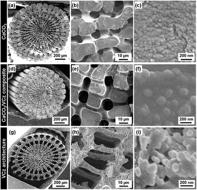
Organic crystals, such as VCz, AB, and PY, were incorporated into the CaCO3 oriented nanocrystals from the melts (Fig. 1a). After the incorporation, the composites of the CaCO3 oriented nanocrystals and the organic crystals were obtained (Fig. 1b). The dissolution of the original CaCO3 led to the formation of organic crystals with the hierarchical morphologies (Fig. 1c). A sea urchin spine was immersed in the solution of sodium hypochlorite to remove the biological macromolecules. Then, the heat treatment was performed at 450 °C for 4 h to expand the nanospace.4 The original material was set with the powders of VCz, AB, and PY on a glass vessel at room temperature. The temperature of the samples was raised to 75 °C, 90 °C, and 180 °C by a heating stage for the incorporation of VCz, AB, and PY from their melts, respectively. The melting points of VCz, AB, and PY are known to be around 65 °C, 70 °C, and 150 °C, respectively. After incubation for 15–30 min, the excess amount of the melts was absorbed by a paper towel before cooling. The further detailed methods are described in the ESI.†The original sea urchin spine shows a complex hierarchical structure (Fig. 2a–c).5 The sponge morphology several tens of micrometer in size was observed on the cross-sectional image (Fig. 2a and b). The sponge morphology consisted of the oriented nanocrystals 20–50 nm in size (Fig. 2b and c). After the incorporation of VCz from the melt, the sponge morphology was preserved without infiltration of the micrometer-scale pores in the sponge with VCz (Fig. 2b and e). The original nanocrystals 20–50 nm in size were not clearly observed after the incorporation of VCz (Fig. 2e and f). Based on these observations, VCz was introduced not into the micrometer-scale pores of the sponge but into the nanospace in the skeletal body. The content of VCz in the composite was estimated to be 15 wt% by thermogravimetric (TG) analysis (Fig. S1 in the ESI†). The hierarchically replicated VCz was obtained after dissolution of the original CaCO3 by hydrochloric acid (HCl) (Fig. 2g–i). The surface layer of the sponge skeletal body several micrometers in thickness was replicated to VCz (Fig. 2e and h). The inside part of the sponge skeletal body was not completely replicated to VCz because a sufficient amount of VCz was not introduced into the part. The replicated VCz sponge structure consisted of connected nanoparticles around 100 nm in size (Fig. 2h and i). When AB and Py were incorporated into the CaCO3 original materials by the present method, the same morphology replication was achieved (Fig. S2 in the ESI†).
In our previous reports, the neat liquid and vapour of the monomers were incorporated into the interspace of the oriented nanocrystals.4 In the current study, the same approach was applied to the incorporation of the organic crystals from their melts. Based on these facts, a variety of hydrophilic and hydrophobic liquids can be introduced into the nanoscale interspace. The results imply that the other organic molecules can be introduced from the liquid and vapour states, regardless of the hydrophilicity, hydrophobicity, and molecular size. The neat liquids of the monomers, such as pyrrole and thiophene derivatives, with low viscosity were incorporated into the nanospace throughout the macroscopic objects.4c Therefore, the whole hierarchical morphology of the original materials was replicated to the polymers. In contrast, the replication from the melts of the organic crystals was achieved on the surface layers of the micrometer-scale objects (Fig. 2e and h). The viscosity of these melts was higher than that of the monomer neat liquids. It is inferred that a sufficient amount of the melts is not introduced into the inside part of the micrometer-scale structures.
The original materials with the hierarchical morphologies based on the oriented nanocrystals were changed from a sea urchin spine to the other materials. A similar morphology replication was achieved by the exoskeleton of a sea star and the synthetic oriented nanocrystals of vaterite CaCO3 (Fig. S3 in the ESI†).15 The present approach can be applied to a variety of combinations of oriented nanocrystals and organic crystals for the morphogenesis.
Crystallinity of the incorporated organic crystals
The crystallinity of the incorporated organic crystals was studied by X-ray diffraction (XRD) and selected-area electron diffraction (SAED) (Fig. 3 and 4). If the size of the incorporated organic crystals is decreased by the confinement in the nanospace, the broadened peaks are observed on the XRD patterns. The commercial VCz crystals showed a number of peaks in the range of 2θ = 5–60° (profile (iv) in Fig. 3a). These peaks were assigned to those listed in the ICDD card (no. 00-033-1964). We focused on the strongest peak at 2θ = 10.2° corresponding to the (200) plane. The peak was observed on the composite containing 15 wt% of VCz (Fig. 3a). The half maximum at full-width (B) and the crystallite size based on Scherrer's equation (t) were estimated from the peaks of a commercial VCz powder, the composite with the incorporation of VCz into the CaCO3 oriented nanocrystal, and the replicated architecture after the dissolution of the original CaCO3 (Fig. 3b). As the reference, VCz powder was recrystallized with the same weight ratio of a commercial CaCO3 crystal several micrometers in size by the same method. The same XRD analyses were performed on AB and PY samples (Table 1 and Fig. S4 in the ESI†). As shown in Table 1, the crystallite sizes were not decreased to single-nanometer size after recrystallization with CaCO3 and incorporation into the oriented nanocrystals. When the commercial organic crystals and their mixtures with commercial CaCO3 crystals were compared, the variations of B and t were within ±10% and ±30% respectively (Table 1). It means that the crystallinity is not so lowered after the recrystallization in the presence of CaCO3 crystals. In the composite states, the decrease of t was a maximum of 51% after incorporation into the nanospace. However, the corresponding crystallite size was about 80 nm in size. The crystallinity of the incorporated organic crystals was not so lowered in the interspace of the oriented nanocrystals. These results imply that the incorporated organic crystals formed the single-crystalline structures within a certain length scale. Since the interspace of the oriented nanocrystals is not closed but continuously widespread in the original materials, the incorporated organic crystals can be grown to the specific sizes under the supercooled conditions.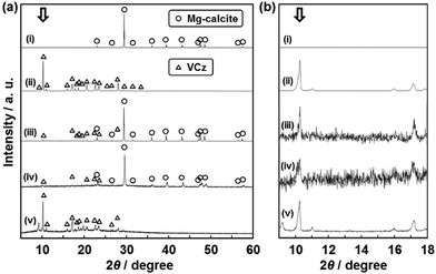 | ||
| Fig. 3 XRD patterns (a) and their magnified ones (b) to study the crystallinity of VCz after incorporation into the oriented nanocrystals. Profiles (i)–(v) represent the following samples: (i) the exoskeleton of a sea urchin spine as the original material before the incorporation of VCz, (ii) a commercial VCz, (iii) the commercial VCz powder recrystallized with a commercial CaCO3 powder, (iv) the composite after the incorporation of VCz into the original material, and (v) the replicated VCz architecture after the dissolution of the original material. Samples (iii) and (iv) contained the same amount of VCz, namely 15 wt%. The B and t were estimated from the peak at 2θ = 10.2° denoted by white arrows (Table 1). | ||
| Sample | VCz | AB | PY | |||
|---|---|---|---|---|---|---|
| Peak | 2θ = 10.3° | 2θ = 17.3° | 2θ = 10.6° | |||
| Crystal plane | (200) | (102) | (001) | |||
| B/10−2° and t/nm | B | t | B | t | B | t |
| a Commercial powders of the organic crystals. b The mixture of the commercial CaCO3 microcrystals and the organic crystals after the recrystallization. c The composite of the CaCO3 oriented nanocrystal and the incorporated organic crystals. d The replicated architecture after the dissolution of the original materials. The detailed calculation method was described in the ESI. | ||||||
| Commerciala | 7.10 | 167 | 8.77 | 95.0 | 12.0 | 82.5 |
| Mixtureb | 7.80 | 146 | 5.69 | 185 | 12.2 | 80.8 |
| Compositec | 12.1 | 81.6 | 4.32 | 220 | 13.7 | 70.1 |
| Replicad | 12.0 | 82.5 | 8.76 | 95.1 | 11.5 | 87.0 |
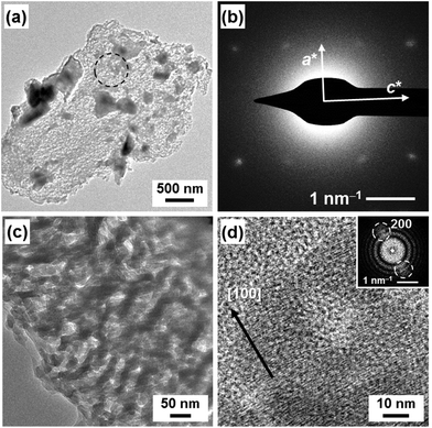
The single-crystalline VCz architecture was observed by field-emission transmission electron microscopy (FETEM) (Fig. 4). In the replicated architectures, the crystallinity was not so changed from that of the composite state after dissolution of the original CaCO3 (Fig. 3 and Table 1). The continuous nanoflakes of VCz around 50 nm were observed in the replicated architecture (Fig. 4a and c). The spot diffraction pattern assigned to VCz was obtained by SAED (Fig. 4b). A series of lattice fringes corresponding to the (200) plane of VCz was observed on the high-resolution TEM image (HRTEM) with the Fourier transform (Fig. 4d). These results suggest that the oriented VCz nanocrystals were formed in the replicated architecture. The XRD and SAED analyses suggest that the incorporated organic crystal formed single-crystalline structures. The nucleation of the incorporated organic crystals occurs on the surface of the original nanocrystals under the supercooled conditions. The growth of the organic crystals from the melts proceeds with the inclusion of the original nanocrystals in the continuous widespread nanospace. Therefore, the replicated materials form the single-crystalline structure in a certain scale.
Photochemical properties of the incorporated organic crystals
Photochemical properties, such as photoluminescence and photoisomerization, depend on the assembly state of molecules. Here the photochemical properties of the incorporated AB and PY were the same as those of the bulk crystalline state (Fig. S5 in the ESI†). The photoisomerization behavior was not observed on the AB incorporated into the nanospace. When the composite was irradiated with the UV light at 365 nm, spectroscopic changes caused by the photoisomerization were not observed (Fig. S5 in the ESI†). If the photoisomerization reaction proceeds, the absorption peaks centered at 330 nm and 440 nm are decreased and increased respectively with irradiation of UV light.28 The photoisomerization reaction was not observed on the bulk AB crystals. The results also supported that AB was incorporated as the crystalline state into the CaCO3 oriented nanocrystals. The photoluminescence spectrum of the incorporated PY showed the same peaks as those corresponding to the bulk crystals (Fig. S5 in the ESI†). The broadened peak around 450 nm originating from the formation of the excimers was observed with UV light excitation at 330 nm. The same spectrum was obtained from the bulk PY crystals. If PY molecules are dispersed as the monomeric molecular state in the host materials, peaks around 400 nm can be observed on the spectrum.29 The photoluminescence spectrum supported that the PY was incorporated as the crystalline state into the nanospace.When AB and PY were introduced into the interspace of the oriented nanocrystals from the dilute solutions,3 these organic compounds were dispersed in the nanospace as the monomeric molecular state. In the present work, these organic molecules were filled as the crystalline state in the nanospace. Therefore, the incorporated organic crystals showed the same photochemical properties as those of the bulk state. Based on the previous and the present studies, the assembly states of the organic molecules can be controlled in the interspace of the oriented nanocrystals by the introduction methods.
Thermal properties of the incorporated organic crystals
The Tm and Tf of VCz, AB, and PY were measured on the incorporated states in the nanospace using differential scanning calorimetry (DSC) (Fig. 5 and Table 2). In previous studies,30,31 the Tm and Tf of the materials were generally lowered with confinement in nanoscale pores. In the present work, the Tm and Tf of the incorporated organic crystals into the oriented nanocrystal are expected to be lower than those of the bulk state. Interestingly, the Tf of the incorporated organic crystals was remarkably increased whereas the Tm was not changed by the incorporation into the nanospace (Fig. 5 and Table 2). The Tm and Tf were measured in the bulk organic crystals, the mixture of commercial CaCO3 microcrystals and organic crystals and the mixture of CaCO3 oriented nanocrystals and organic crystals. The heating and cooling of these samples were repeated by three cycles in the DSC measurement. The Tm and Tf of the VCz, AB, and PY were estimated from the onset temperature at the second cycles (Table 2). The first heating and cooling processes were regarded as the preparation of the composites of the CaCO3 oriented nanocrystals and the organic crystals. In the other samples, the first cycle corresponded to the recrystallization of the organic compounds. As for VCz, the Tm was observed to be around 62 °C in the heating processes regardless of the samples (Fig. 5 and Table 2). In contrast, the Tf of the VCz in the oriented nanocrystal was raised from 24 °C to 53 °C in the cooling process. The same phase transition behavior, namely the rise of the Tf, was observed on the AB and PY (Table 2 and Fig. S6 in the ESI†).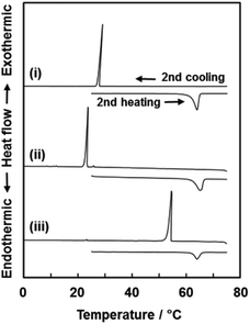 | ||
| Fig. 5 DSC thermograms of a VCz commercial powder (i), the mixture of commercial CaCO3 and VCz powders (ii), and the mixture of the CaCO3 original material and a VCz commercial powder (iii). All the thermograms were obtained from the second heating and cooling processes. The onset temperature was used for the estimation of Tm and Tf in Table 2. | ||
| Sample | VCz | AB | PY | |||
|---|---|---|---|---|---|---|
| T m, Tf/°C | T m | T f | T m | T f | T m | T f |
| a The following samples were put in the DSC sample vessel. The onset temperature of the second cycles was adopted as the Tm and Tf listed in this table. b Commercial powders of the organic crystals. c The mixture of the commercial CaCO3 microcrystals and the organic crystals after the recrystallization. d The composite of the CaCO3 oriented nanocrystals and the incorporated organic crystals. | ||||||
| Commercialb | 62.0 | 26.7 | 67.1 | 24.6 | 149 | 121 |
| Mixturec | 62.7 | 22.7 | 67.2 | 42.6 | 148 | 130 |
| Composited | 62.4 | 53.3 | 67.4 | 59.5 | 149 | 142 |
The rise of the Tf is ascribed to the promotion of heterogeneous nucleation in the interspace of the oriented nanocrystal. The surface of the unit nanocrystals provides the heterogeneous nucleation sites in the melts of the organic compounds. A couple of previous studies showed the simultaneous rise of Tf and Tm.32–34 The Tf of the polymers was raised when the inorganic nanoparticles were added into the polymer melts.32 The presence of inorganic nanoparticles promoted the crystallization of the polymers through the specific interaction. The Tf of carbon tetrachloride was elevated by the confinement in graphitic carbon.33 A calculation study also supported the experimental results.34 When the interactions between the pore wall and the incorporated molecules were stronger than those between the incorporated molecules, the Tf and Tm are raised by a decrease in the pore size. In the present work, only the Tf was raised by the incorporation into the nanoscale interspace. It is inferred that the sites for heterogeneous nucleation are provided by the surface of the unit nanocrystals. The crystal growth proceeds in the nanospace under the supercooled conditions. In contrast, the Tm was not changed by the incorporation into the nanospace. Since the organic crystals are grown to the specific size comparable to the bulk size, the melting behavior is not distinct from the bulk crystals. Therefore, the Tm is not influenced by the surface of the unit nanocrystals. The present phase transition behaviour is specific in the interspace of the oriented nanocrystals. A further study is needed for the understanding and application of the thermal properties.
Polymerization of VCz and the formation of the charge-transfer complex
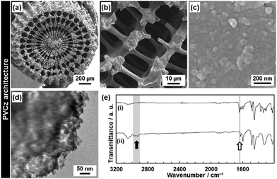
PVCz was synthesized by the polymerization of the VCz in the composite state. In previous studies, PVCz was synthesized in the mesoporous materials and metal–organic frameworks.35 In the present study, the hierarchical morphology of the PVCz was obtained after the dissolution of the original CaCO3 material (Fig. 6). The CT complex was prepared by the immersion of the resulting PVCz in the toluene solution of TNF (Fig. 7). The PVCz hierarchical architectures formed a larger amount of the CT complex than commercial PVCz powder of several micrometers in size. The polymerization method was referred to previous reports.36 The VCz incorporated into the oriented nanocrystal was immersed in a chloroform solution containing iron(III) chloride (FeCl3). After the polymerization, the original CaCO3 material was dissolved from the composite by HCl. The resulting PVCz showed similar hierarchical morphologies to the VCz (Fig. 2 and 6). A sponge structure consisting of nanoparticles 50 nm in size was obtained (Fig. 6a–d). The formation of PVCz was confirmed by the FT-IR spectrum (Fig. 6e).37 A decrease and an increase in the absorptions corresponding to the C![[double bond, length as m-dash]](https://www.rsc.org/images/entities/char_e001.gif) C stretching vibration and the C–H stretching vibration, respectively, were observed after the polymerization. The crystallinity of VCz disappeared after the polymerization. When the VCz replicated architecture was used for the polymerization, the hierarchical morphologies were not kept after the dissolution of the original CaCO3. The hierarchical morphology of PVCz was only obtained by the polymerization in the composite state. The interspace of the oriented nanocrystals and the framework of the macroscopic morphology contributes to the morphogenesis with the polymerization.
C stretching vibration and the C–H stretching vibration, respectively, were observed after the polymerization. The crystallinity of VCz disappeared after the polymerization. When the VCz replicated architecture was used for the polymerization, the hierarchical morphologies were not kept after the dissolution of the original CaCO3. The hierarchical morphology of PVCz was only obtained by the polymerization in the composite state. The interspace of the oriented nanocrystals and the framework of the macroscopic morphology contributes to the morphogenesis with the polymerization.
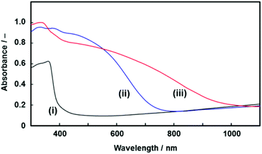 | ||
| Fig. 7 UV-Vis absorption spectra of the resulting PVCz architecture (i), the CT complex of a commercial PVCz with TNF (ii), and the CT complex of the PVCz hierarchical architecture with TNF (iii). | ||
The CT complex was formed by the immersion of the resulting PVCz in a toluene solution of TNF. The PVCz had an absorption edge around 370 nm. A redshift of the absorption edge was observed by the immersion in the toluene solution of TNF (Fig. 7). Based on previous reports,38 the redshift of the absorption spectrum is ascribed to the formation of the CT complex. The amount of the CT complex was estimated from the absorption peaks of the FT-IR spectra (Fig. S7 in the ESI†). About 11.2 mol% of the VCz units in the PVCz hierarchical architecture formed the CT complex with TNF, whereas 1.70 mol% of the VCz units in a commercial PVCz powder were used for the formation of the CT complex. Under the same conditions, the PVCz hierarchical architecture formed a 6.6 times higher amount of the CT complex than commercial PVCz powder. The specific surface area contributed to the formation of a larger amount of the CT complex. The morphology control of organic materials based on the present approach has potential use for the improvement of the properties.
Conclusions
Organic crystals, such as VCz, AB, and PY, were introduced into the interspace of the CaCO3 oriented nanocrystals from the melts. The incorporation effects of the nanospace on the morphologies and properties of organic crystals incorporated were systematically studied. The original materials and the incorporated organic crystals formed the composite. The hierarchical morphology of the organic crystals was obtained after the dissolution of the original materials. Although the melts of the organic crystals have high viscosities, the liquids were incorporated and crystallized in the nanospace. The crystallinity of the incorporated organic crystals was not lowered in the nanospace. The single-crystalline structure of the incorporated organic materials was formed in the composite states and the replicated architectures. The crystallization of the melts and the subsequent growth proceed in the nanospace with the inclusion of the original materials under supercooled conditions. A unique phase transition behavior was observed on the incorporated organic crystals in the nanospace. The incorporated organic crystals showed an elevation of Tf, whereas the Tm was not changed from the bulk state. It is inferred that the heterogeneous nucleation was promoted by the high specific surface area based on the unit nanocrystals. The incorporated organic crystal, namely VCz, was polymerized in the composite state. The hierarchical morphology of PVCz was obtained after the dissolution of the original material. The resulting PVCz formed a larger amount of the CT complex than the commercial PVCz powder. The present new results can be applied to a variety of combinations of oriented nanocrystals and organic materials. The morphologies and properties of organic crystals can be tuned by the incorporation into the nanoscale interspace of the hierarchically organized materials.Acknowledgements
This work was partially supported by Grants-in-Aid for Scientific Research (no. 22107010) on Innovative Areas on “Fusion Materials: Creative Development of Materials and Exploration of Their Function through Molecular Control” (no. 2206) (H.I.) from the Ministry of Education, Culture, Sports, Science, and Technology and for Young Scientist (A, no. 22685022) (Y.O.) from the Japan Society for the Promotion of Science. We thank Prof. Y. Katayama for recording DSC thermograms.Notes and references
- (a) H. Cölfen and S. Mann, Angew. Chem., Int. Ed., 2003, 42, 2350 CrossRef PubMed; (b) H. Cölfen and M. Antonietti, Angew. Chem., Int. Ed., 2005, 44, 5576 CrossRef PubMed; (c) M. Niederberger and H. Cölfen, Phys. Chem. Chem. Phys., 2006, 8, 3271 RSC; (d) H. Imai, Y. Oaki and A. Kotachi, Bull. Chem. Soc. Jpn., 2006, 79, 1834 CrossRef CAS; (e) L. Zhou and P. O'Brien, Small, 2008, 4, 1566 CrossRef CAS PubMed; (f) L. Zhou and P. O'Brien, J. Phys. Chem. Lett., 2012, 3, 620 CrossRef CAS; (g) Y. Oaki and H. Imai, SPR Nanosci., 2013, 1, 1 CAS.
- H. Cölfen and M. Antonietti, Mesocrystals and Nonclassical Crystallization, John Wiley & Sons, 2008 Search PubMed.
- (a) Y. Oaki and H. Imai, Angew. Chem., Int. Ed., 2005, 44, 6571 CrossRef CAS PubMed; (b) Y. Oaki and H. Imai, Bull. Chem. Soc. Jpn., 2009, 82, 613 CrossRef CAS.
- (a) Y. Oaki, M. Kijima and H. Imai, J. Am. Chem. Soc., 2011, 133, 8594 CrossRef CAS PubMed; (b) M. Kijima, Y. Oaki, Y. Munekawa and H. Imai, Chem. – Eur. J., 2013, 19, 2284 CrossRef CAS PubMed; (c) Y. Munekawa, Y. Oaki and H. Imai, Langmuir, 2014, 30, 3236 CrossRef CAS PubMed; (d) R. Muramatsu, Y. Oaki, K. Kuwabara, K. Hayashi and H. Imai, Chem. Commun., 2014, 50, 11840 RSC.
- (a) Y. Oaki, A. Kotachi, T. Miura and H. Imai, Adv. Funct. Mater., 2006, 16, 1633 CrossRef CAS; (b) Y. Oaki and H. Imai, Small, 2006, 2, 66 CrossRef CAS PubMed.
- S. H. Yu, M. Antonietti, H. Cölfen and J. Hartmann, Nano Lett., 2003, 3, 379 CrossRef CAS.
- (a) A. Sugawara, T. Nishimura, Y. Yamamoto, H. Inoue, H. Nagasawa and T. Kato, Angew. Chem., Int. Ed., 2006, 45, 2876 CrossRef CAS PubMed; (b) T. Nishimura, T. Ito, Y. Yamamoto, M. Yoshio and T. Kato, Angew. Chem., Int. Ed., 2008, 47, 2800 CrossRef CAS PubMed.
- (a) Y. Oaki and H. Imai, Adv. Funct. Mater., 2005, 15, 1407 CrossRef CAS; (b) Y. Oaki and H. Imai, Chem. Commun., 2005, 6011 RSC.
- L. Zhou, D. S. Boyle and P. O'Brien, J. Am. Chem. Soc., 2007, 130, 1309 CrossRef PubMed.
- M. Kijima, Y. Oaki and H. Imai, Chem. – Eur. J., 2011, 17, 2828 CrossRef CAS PubMed.
- Y. Oaki, N. Yagita and H. Imai, Chem. – Eur. J., 2012, 18, 110 CrossRef CAS PubMed.
- I. Bilecka, A. Hintennach, I. Djerdj, P. Novák and M. Niederberger, J. Mater. Chem., 2009, 19, 5125 RSC.
- J. Ye, W. Liu, J. Cai, S. Chen, X. Zhao, H. Zhou and L. Qi, J. Am. Chem. Soc., 2011, 133, 933 CrossRef CAS PubMed.
- F. Dang, T. Hoshino, Y. Oaki, E. Hosono, H. Zhou and H. Imai, Nanoscale, 2013, 5, 2352 RSC.
- H. Imai, N. Tochimoto, Y. Nishino, Y. Takezawa and Y. Oaki, Cryst. Growth Des., 2012, 12, 876 CAS.
- (a) M. Ogawa and K. Kuroda, Bull. Chem. Soc. Jpn., 1997, 70, 2593 CrossRef CAS; (b) B. J. Scott, G. Wrinsberger and G. D. Stacky, Chem. Mater., 2001, 13, 3140 CrossRef CAS; (c) Y. Wan, H. Yang and D. Zhao, Acc. Chem. Res., 2006, 39, 423 CrossRef CAS PubMed; (d) Y. Yamauchi and K. Kuroda, Chem. – Asian J., 2008, 3, 664 CrossRef CAS PubMed; (e) T. Kimura and K. Kuroda, Adv. Funct. Mater., 2009, 19, 511 CrossRef CAS; (f) N. Mizoshita, T. Tani and S. Inagaki, Chem. Soc. Rev., 2011, 40, 789 RSC; (g) S. Horike, S. Shimomura and S. Kitagawa, Nat. Chem., 2009, 1, 695 CrossRef CAS PubMed; (h) T. Uemura, N. Yanai and S. Kitagawa, Chem. Soc. Rev., 2009, 38, 1228 RSC.
- (a) E. Ruiz-Hitzky, Adv. Mater., 1993, 5, 334 CrossRef CAS; (b) T. Tajima and T. Aida, Chem. Commun., 2000, 2399 RSC; (c) R. A. Caruso and M. Antonietti, Chem. Mater., 2001, 13, 3272 CrossRef CAS; (d) H. P. Hentze and M. Antonietti, Curr. Opin. Solid State Mater. Sci., 2001, 5, 343 CrossRef CAS; (e) D. J. Cardin, Adv. Mater., 2002, 14, 553 CrossRef CAS.
- K. J. C. van Bommel, A. Friggeri and S. Shinkai, Angew. Chem., Int. Ed., 2003, 42, 980 CrossRef CAS PubMed.
- (a) T. Kato, Science, 2002, 295, 2414 CrossRef CAS PubMed; (b) T. Kato, N. Mizoshita and K. Kishimoto, Angew. Chem., Int. Ed., 2006, 45, 38 CrossRef CAS PubMed; (c) T. Kato, T. Yasuda, Y. Kamikawa and M. Yoshio, Chem. Commun., 2009, 729 RSC; (d) T. Ichikawa, M. Yoshio, S. Taguchi, J. Kagimoto, H. Ohno and T. Kato, Chem. Sci., 2012, 3, 2001 RSC.
- A. R. Murphy and J. M. J. Fréchet, Chem. Rev., 2007, 107, 1066 CrossRef CAS PubMed.
- L. C. Palmer and S. I. Stupp, Acc. Chem. Res., 2008, 41, 1674 CrossRef CAS PubMed.
- S. J. Holder and N. A. J. M. Sommerdijk, Polym. Chem., 2011, 2, 1018 RSC.
- (a) H. S. Nalwa, H. Kasai, S. Okada, H. Oikawa, H. Matsuda, A. Kakuta, A. Mukoh and H. Nakanishi, Adv. Mater., 1993, 5, 758 CrossRef CAS; (b) D. Horn and J. Rieger, Angew. Chem., Int. Ed., 2001, 40, 4330 CrossRef CAS; (c) Y. S. Zhao, H. Fu, A. Peng, Y. Ma, D. Xiao and J. Yao, Adv. Mater., 2008, 20, 2859 CrossRef CAS; (d) R. Li, W. Hu, Y. Liu and D. Zhu, Acc. Chem. Res., 2010, 43, 529 CrossRef CAS PubMed.
- (a) H. P. Cong and S. H. Yu, Chem. – Eur. J., 2007, 13, 1533 CrossRef CAS PubMed; (b) H. P. Cong and S. H. Yu, Adv. Funct. Mater., 2008, 18, 195 CrossRef CAS.
- (a) Y. Ma, G. Mehltretter, C. Plüg, N. Rademacher, M. U. Schmidt and H. Cölfen, Adv. Funct. Mater., 2009, 19, 2095 CrossRef CAS; (b) Y. Jiang, H. Gong, D. Volkmer, L. Gower and H. Colfen, Adv. Mater., 2011, 23, 3548 CrossRef CAS PubMed.
- M. Huang, U. Schilde, M. Kumke, M. Antonietti and H. Cölfen, J. Am. Chem. Soc., 2010, 132, 3700 CrossRef CAS PubMed.
- (a) S. Mann, Nature, 1993, 365, 499 CrossRef CAS; (b) T. Kato, Adv. Mater., 2000, 12, 1543 CrossRef CAS; (c) S. H. Yu and H. Cölfen, J. Mater. Chem., 2004, 14, 2124 RSC; (d) A.-W. Xu, Y. Ma and H. Cölfen, J. Mater. Chem., 2007, 17, 415 RSC; (e) F. C. Meldrum and H. Cölfen, Chem. Rev., 2008, 108, 4332 CrossRef CAS PubMed; (f) N. A. J. M. Sommerdijk and G. de With, Chem. Rev., 2008, 108, 4499 CrossRef CAS PubMed; (g) L. B. Gower, Chem. Rev., 2008, 108, 4551 CrossRef CAS PubMed; (h) T. Kato, T. Sakamoto and T. Nishimura, MRS Bull., 2010, 35, 127 CrossRef CAS; (i) H. Imai and Y. Oaki, MRS Bull., 2010, 35, 138 CrossRef CAS.
- G. S. Kumar and D. C. Neckers, Chem. Rev., 1989, 89, 1915 CrossRef CAS.
- T. Förster, Angew. Chem., Int. Ed. Engl., 1969, 8, 333 CrossRef.
- (a) H. K. Christenson, J. Phys.: Condens. Matter, 2001, 13, R95 CrossRef CAS; (b) C. A. Simionesco, B. Coasne, G. Dosseh, G. Dudziak, K. E. Gubbins, R. Radhakrishnan and M. Sliwinska-Bartkowiak, J. Phys.: Condens. Matter, 2006, 18, R15 CrossRef PubMed.
- (a) C. L. Jackson and G. B. McKenna, J. Chem. Phys., 1990, 93, 9002 CrossRef CAS PubMed; (b) J. C. van Miltenburg and J. P. van der Eerden, J. Cryst. Growth, 1993, 128, 1143 CrossRef CAS; (c) A. Schreiber, I. Ketelsen and G. H. Findenegg, Phys. Chem. Chem. Phys., 2001, 3, 1185 RSC; (d) G. Dosseh, Y. Xia and C. Alba-Simionesco, J. Phys. Chem. B, 2003, 107, 6445 CrossRef CAS.
- (a) G. Z. Papageorgiou, D. S. Achilias, D. N. Bikiaris and G. P. Karayannidis, Thermochim. Acta, 2005, 427, 117 CrossRef CAS PubMed; (b) P. Maiti, P. H. Nam, M. Okamoto, N. Hasegawa and A. Usuki, Macromolecules, 2002, 35, 2042 CrossRef CAS; (c) P. Maiti and M. Okamoto, Macromol. Mater. Eng., 2003, 288, 440 CrossRef CAS; (d) S. Zhang, A. Zhu and S. Dai, J. Appl. Polym. Sci., 2011, 121, 3007 CrossRef CAS; (e) Z. Peng and D. Chen, J. Polym. Sci., Part A: Polym. Phys., 2006, 44, 534 CrossRef CAS.
- K. Kaneko, A. Watanabe, T. Iiyama, R. Radhakrishan and K. E. Gubbins, J. Phys. Chem. B, 1999, 103, 7061 CrossRef CAS.
- M. Miyahara and K. E. Gubbins, J. Chem. Phys., 1997, 106, 2865 CrossRef CAS PubMed.
- (a) S. Spange, A. Gräser, H. Müller, Y. Zimmermann, P. Rehak, C. Jäger, H. Fuess and C. Baehtz, Chem. Mater., 2001, 13, 3698 CrossRef CAS; (b) T. Uemura, N. Uchida, A. Asano, A. Saeki, S. Seki, M. Tsujimoto, S. Isoda and S. Kitagawa, J. Am. Chem. Soc., 2012, 134, 8360 CrossRef CAS PubMed.
- (a) D. B. Romero, M. Schaer, M. Leclerc, D. Adès, A. Siover and L. Zuppiroli, Synth. Met., 1996, 80, 271 CrossRef CAS; (b) P. X. Thinh, C. Basavaraja, W. J. Kim and D. S. Huh, Polym. Compos., 2011, 32, 1772 CrossRef CAS; (c) C. Bsavaraja, W. J. Kim, D. G. Kim and D. S. Huh, Polym. Compos., 2011, 32, 1077 CrossRef.
- M. Sacak, U. Akbulut, C. Cheng and D. N. Batchelder, Polymer, 1994, 35, 2495 CrossRef CAS.
- (a) B. Andre, R. Lever and J. Y. Moisan, Chem. Phys., 1989, 137, 281 CrossRef CAS; (b) I. Glowacki, J. Jung and J. Ulański, Synth. Met., 2000, 109, 143 CrossRef CAS; (c) J. Jung, I. Glowacki and J. Ulański, J. Chem. Phys., 1999, 110, 7000 CrossRef CAS PubMed.
Footnote |
| † Electronic supplementary information (ESI) available. See DOI: 10.1039/c4nr05317f |
| This journal is © The Royal Society of Chemistry 2015 |

