A thermal diode and novel implementation in a phase-change material
E.
Pallecchi
a,
Z.
Chen
b,
G. E.
Fernandes
b,
Y.
Wan
b,
J. H.
Kim
b and
J.
Xu
*b
aInstitut d'Electronique, de Microélectronique et de Nanotechnologie, UMR-CNRS 8520, BP 60069 Avenue Poincaré, F-59652 Villeneuve d'Ascq, France
bBrown University, School of Engineering, 182 Hope Street, Providence, RI 02912, USA. E-mail: Jimmy_Xu@brown.edu
First published on 18th November 2014
Abstract
The development of devices suitable for heat management requires materials whose thermal properties and synthesis are well controlled. Phase-changing materials are both highly tunable and well characterized, and therefore promising as building blocks for thermal devices. Here we introduce a novel design of a thermal diode based on a phase changing material, and we validate it by realizing a proof-of-concept device consisting of a series of PNIPAM (the phase changing material) and PDMS. Thermal measurements of our thermal diode demonstrate heat rectification, with a rectification coefficient on the order of two. A simple model is used to describe the experimental results.
Conceptual insightsThis report provides a thermal diode design based on phase changing materials, as well as a proof-of-concept device obtained by a series of PNIPAM (the phase-changing material) and PDMS. The name thermal diode is used in analogy to the electronic diode, as both devices act as a rectifier. Indeed the heat flow can be controlled by using a thermal device, similarly to the charge flow which is regulated by the p–n-junctions. To date no clear material has emerged as a perfect candidate for thermal diodes, and most likely several materials will be used in the future because of the broad spectrum of applications, ranging from construction to nano-electronics. Our work demonstrates the feasibility of thermal diodes using well known phase change materials to achieve high-rectification ratios, and will promote the development of more complex phase changing materials optimized for thermal applications. |
An intriguing and yet open question is how to manipulate the heat flowing between two systems. Indeed, heat handling is nowadays a major bottleneck in many fields. For instance, integration of micro- and nano-scale electronic devices is limited by power dissipation, since current technology allows fabricating devices with extremely high density, but it is impossible to handle the heat that they generate by optimized design solely. The importance of heat management is not only limited to nanoscale electronic devices, but is crucial in many fields, such as aeronautics. Because of the disruptive potential of heat handling, the interest in novel materials which allows controlling the heat flow is rapidly growing.1–5 A smart material whose heat conductivity/isolation could adjust to the changes of the external temperature would allow for a next generation of greener, less energy-hungry and environmentally friendly buildings. Indeed, new materials whose thermal properties have been engineered are probably needed for a sustainable world.6 Applications such as energy harvesting and intelligent clothes can also be foreseen. At the same time, since active manipulation of heat flow is yet to be explored largely, materials whose production is well controlled are the most suitable for first generation thermal devices. Indeed, well characterized materials could boost the development of the thermal devices, and could serve as a starting point for more advanced materials for next-generation devices.
A fundamental yet simple thermal device which has been proposed in the literature is the thermal rectifier or thermal diode, its operating principle being to conduct heat better in one direction than in the opposite.7 The thermal diode is clearly named in analogy to its electronics counterpart, the electronic diode. As we will discuss in more detail below, the analogy between heat flow and electron flow is not limited to the case of the thermal diode, and a new class of thermal devices can be expected in the future, forming the field of what has been called phononics or heattronics.8 Nevertheless, despite this growing interest, demonstrated by the number of theoretical propositions, the experimental results are still limited either in terms of performances or available material choices (see the reviews8,9 and the references therein). As a result, the application of thermal diodes is limited to ‘niche’ applications such as heat distribution in spacecraft. Since the observation of thermal rectification by Starr10 several groups have realized thermal diodes based on different mechanisms: evaporation/condensation,11 infrared emission,2 the difference in thermal coefficient at the junctions between two materials,12 thermal potential barrier and strain at two material contacts, and the phonon anharmonicity in 1D lattices7 (see also reviews8,9,11 and therein references). Recently, a bulk thermal diode using two different cobalt oxides was reported by Kobayashi et al.,13 and nanostructured and two-dimensional materials are also being sought for more efficient thermal rectification. Pioneering work on solid state thermal diode based on nanomaterials has been demonstrated by Chang et al.1 using mass loaded nanotubes, and currently several studies on carbon based materials have been reported.14,15 For uses that may lead to a real breakthrough in thermal management, either at the nano or large scale, novel solutions exploiting different materials are needed. Unlike the case in electronics where a single material, silicon dominates justifiably, the material choices for thermal diodes could vary widely for different applications and in different temperature ranges.
Here we report a novel type of thermal rectifier and its implementation based on poly(N-isopropylacrylamide) (PNIPAM). The novelty of this type of thermal rectifier lies in the use of a phase change material. As such, there is an extra degree of freedom in designing the activation temperature of the rectifying function, much like the activation voltage for an electronic diode which can be varied to great benefits in electronic circuits with different choices of materials and/or doping levels. For proof-of-concept demonstration, we choose to work with a well-characterized material, PNIPAM, whose phase transition occurs at 32 °C, where it changes phase with increasing temperature from hydrophilic to hydrophobic.16–18 The phase change leads to a change in the thermal conductivity, which we exploit to implement a thermal diode design consisting of a serial combination of such a material with another material of nearly constant thermal conductivity, polydimethylsiloxane (PDMS) in our case. The emphasis of the exploration of this new pathway is at this stage placed on ‘proving the concept’ rather than its absolute performance.
In general, the design and concept can be extended to other phase-change materials in which the material phase change is normally accompanied by a marked change in thermal (and often electrical) conductivity. This is easily seen through analysing the general case of a thermal diode with a junction of two materials whose thermal conductivities differ significantly or even have opposite temperature dependences. Then, we discuss in more detail our deviation in approach and design, and a first experimental realization of a thermal diode based on a junction composed of PNIPAM and PDMS, for which we demonstrate thermal rectification. Finally, we present an empirical model to explain our observation and discuss the implications of such a thermal diode as a building block for more complex devices such as thermal-transistors and even possibly thermal logic-gates.
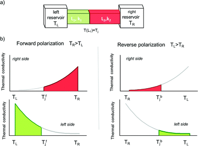
The Fourier law is an empirical law that describes heat flow. It also provides the definition of the thermal conductivity k, which relates the variation of heat flux dq/dt to the temperature gradient ΔT: dq/dt = −kΔT. In the steady state, it can be shown that the Fourier law for a material connecting two thermal reservoirs is analogous to the Ohm's law, where the heat flux (equivalent to electrical current) is given by the product of the thermal conductance and the temperature difference (the driving force, equivalent of voltage difference), and the temperature decreases linearly along the thermal resistors, similarly to the case of voltage along an electrical resistor. For a junction formed by two materials with different thermal conductivities k1 and k2, and lengths L1 and L2, the temperature at the junction Tj is easily obtained by imposing that the heat current is equal on both sides of the junction. A necessary condition to obtain rectification is that the properties of the junction change upon reversing the temperature of the thermal contacts; in other words, since geometry is fixed, thermal conductivity depends on the temperature. Then the asymmetry arises from the sign of the temperature change and the actual temperature profile. This degree of asymmetry (rectification ratio) can be adjusted by choosing the materials and the geometry variations (i.e. L1/L2, the cross-section, etc.). In general, the thermal conductivity can be strongly dependent on temperature, given the different phonon modes that can be excited at different temperatures, and the temperature coefficient of the thermal conductivity differs from material to material, with even possibly opposite signs.19 A thermal diode can then be realized by coupling two materials whose thermal conductivities have different and/or opposite temperature dependences. In the forward polarized configuration, because of the applied temperature difference, both sides of the junctions operate in the temperature regime where they are highly conductive. In the opposite configuration both parts are less conductive, so that a rectification effect can be obtained. A sketch of the thermal diode and the working principle is depicted in Fig. 1.
We illustrate the case where the two materials have k with opposite temperature dependences (rectification can also be obtained with materials with k having different slopes but the same sign, not shown). Clearly, the thermal diode, in both cases, conducts heat from the highest to the lowest reservoir in agreement with the Clausius statement of the second principle of thermodynamics. Several combinations of materials can be chosen, for example bismuth/graphite or sapphire/nanotubes, depending on the operating temperature.
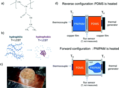
The thermal diode design we propose can be implemented in a specific device consisting of a serial combination of PNIPAM and PDMS polymers. And it happens to operate in a temperature range around human comfort, although the primary motivation for choosing these materials was that they are well-developed and well-behaved, and thus well-suited for the purpose of proving the design concept. The strong temperature dependence of thermal conductivity in PNIPAM and the designed structural asymmetry result in a non-linear heat flow through the device, preferentially in one direction versus the other. In its hydrophilic phase, water in the PNIPAM is bound to, or immobilized by, hydrophilic groups in the polymer chains, but when the temperature rises above the phase transition temperature, the so-called lower-critical-solution-temperature (LCST), the water becomes unbound and the polymer changes its conformation and hydrophilicity, the water molecules are expelled out while the polymer shrinks in volume (Fig. 2b). Convection current through the expelled water creates an additional and more conducive heat transfer pathway, lowering its overall thermal resistance. This decrease in thermal resistance allows higher heat flux or current to flow. The basic concept and device configuration is generic enough that can be adapted to many other material pairs, including metal oxides, such as vanadium oxide, and semiconductors such as Germanium–Antimony–Tellurium (GST).
In our proof-of-concept realization, the device was simply constructed by filling two plastic cylindrical tubes with equal volumes of PDMS and PNIPAM, which are then sealed by copper films and mounted in series. The diameter of the cross-section of the PDMS slab and the PNIPAM compartment are approximatively 15 mm, the height of each cylinder being 7 mm. A sketch of the device and experiment are shown in Fig. 2. Two thermocouples are mounted inside the copper plates which define the left and right side of the diode, the copper plates are in direct contact either with PDMS or PNIPAM. One side of the diode was then placed in thermal contact with a thermal generator Laird CP14, while the other was thermalized with a large metallic plate. The heat flux across the diode was monitored with a heat flux meter (Omega HSF-3 thin film flux sensor). The whole setup was operated in a rough vacuum to minimize heat losses due to the convection. In our experiment, the power to the thermal generator was increased incrementally and the heat flux was recorded. The diode operates in the forward mode (high k) when the PNIPAM side is heated and in the reverse mode when the PDMS side is heated (low k).
In the reverse mode, the temperature drop over the low-thermo-conductivity PDMS was so large that PNIPAM phase change did not occur until the heating power exceeds its ‘break-down’ threshold, but when heat was applied directly to the PNIPAM side, the phase change occurred and reduced the total thermal resistance. Separation of water and shrinkage of PNIPAM was observed in the forward polarization as represented in Fig. 2a.
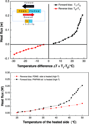
The measured heat flux as a function of temperature difference between hot and cold sides is plotted in Fig. 3. In the top plot of Fig. 3 we present the heat flux for both forward (red) and reversed (dark) configuration as a function of the heated side. The data are re-plotted in Fig. 3 (bottom) as a function of the temperature difference T1 − T0 to highlight the rectification. This second representation is dual to the I–V characteristic plot in electronic devices; the analogy between our thermal data and those of an electrical diode is evident. The observed behavior corresponds to a decrease in the effective thermal resistance of our PNIPAM–PDMS structure which occurs as a result of the PNIPAM's change of its hydrophilicity followed by a phase separation of water from the PNIPAM when heated above LCST. Above the LCST, convection of water within the PNIPAM compartment becomes possible, creating an additional heat conduction path and thus a decrease in the thermal resistance. The forward direction shows an increase in thermal conductance above the phase transition temperature, equivalent to the ‘built-in’ potential in an electronic diode, while the conductance in the reverse direction exhibited only gradual change with temperature.
The thermal conductance corresponds to the slope of the curves in Fig. 3. For the determination of the conductance value we limited the fit of our data to the linear regime where Q ∼ kΔT, that is for a temperature of the heated side 30 < T < 45°. For the forward bias (black curve) we find 0.0025 ± 0.0006 W K−1, while the slope of the reverse-bias curve (red) is about 0.0049 ± 0.0006 W K−1. The deviation at higher temperature is still under investigation, and could be due to the evaporation of part of the water expelled by PNIPAM. The effective thermal conductivity across the device can be computed as κeff = LQ/(AΔT), where L is the length of the device, A is the total surface area, and Q/ΔT is the slope. In the forward direction κeff = 0.2 W (m K)−1 above the phase transition, κeff = 0.1 W (m K)−1 below the transition temperature. The reverse direction is nearly the same as the forward direction below the Tc as expected. This gives a rectification ratio of approximately 2 between the forward and reverse modes of operation. The thermal conductivity on the forward direction is smaller yet comparable to that expected for a PDMS/water junction of equal volume, for which κeff = 1/2(κH2O + κPDMS) = 0.35 W (m K)−1. Nevertheless, the proof-of-concept tests have shown that the thermal conductivity change in the forward direction results in an increase in the conductivity across the composite and that this principle can be used in other materials that have a strong temperature dependence of thermal conductivity.
A simple steady state thermal resistance model can be used to analyze the behavior of the PNIPAM–PDMS system. The device in the forward configuration is described by the following equations:
| T0 − Tj = Q × R0 + (Tj − T1) |
| Tj − T1 = Q × R1(Tavg) |
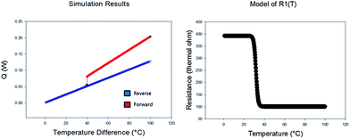
Where Tc is the transition temperature (≈32 °C) and c is a scaling factor. Despite the simplicity of the model, we solve the system of equation numerically due to the highly nonlinear character of the thermal resistance of the PNIPAM at the phase transition. For the numerical solution of our model we consider thermal resistances values which are comparable, even though not identical, to those of the actual thermal diode we realized: R1 goes from 392 to 100 at high temperature, and R0 we take a resistance of 390 K W−1. The temperature T0 (cold side of the junction) is kept at zero while T1 is varied from zero to 100°.
The form of R1versus T1 and the result of the numerical simulation for the power Q as a function of the temperature gradient T1 − T0, are shown in Fig. 4. The model reproduces well the heat flow rectification observed for our device; moreover the estimates thermal rectification coefficient is of the order two, close to the experimental value.
To validate our findings we performed a control experiment in a well-known junction where no rectification was expected. To meet this goal we measured using the same setup a junction formed by two identical cylinders of PDMS (we replaced PNIPAM with a second PDMS cylinder). As expected we did not observe any rectification, the thermal conductivity for the first direction 0.16 ± 0.3 W K−1 and 0.18 ± 0.3 W K−1 for the opposite (obtained by inverting the order of the two PDMS cylinders) consistent with what is reported in the literature for PDMS. No rectification was observed for PDMS/epoxy, nor PDMS/bismuth.
Conclusions
In conclusion, we introduced a novel design of a thermal diode based on phase changing materials. The design was validated by realizing a proof-of-concept thermal diode consisting of a series of phase changing PNIPAM and PDMS. We demonstrated that our device is a thermal rectifier, with a rectifying ratio on the order of two. The values of rectification coefficient can be increased by optimizing the geometry of the device. A second and more promising route for optimization is to synthesize phase changing materials with a larger conductivity gradient between the hydrophilic and hydrophobic phase. A simple model is used for a qualitative explanation of our experimental observations. Our work paves the way for the application of PNIPAM and related phase changing materials in the future generation of thermal-devices. Future efforts along this direction could be in finding solid state materials that have a large temperature dependence on the thermal conductivity and creating a solid state thermal switch or even a thermal memristor. Further exploration of thermal rectification in other materials with temperature dependent thermal conductivity, such as eicosane based PCMs or solid oxides, deserves additional attention because of the great potential for thermal devices, whose development is required for innovative energy solutions.Acknowledgements
The authors would like to thank G. Dambrine and D. Pavlidis for enabling the collaboration between the IEMN and Brown teams and H. Happy for the discussion. The Brown team acknowledges AFOSR, AOARD, and NSF for their support. The IEMN acknowledges EQUIPEX ExCELSiOR for the financial support.Notes and references
- C. W. Chang, D. Okawa, A. Majumdar and A. Zettl, Science, 2006, 314, 1121 CrossRef CAS PubMed.
- P. Ben-Abdallah and S.-A. Biehs, Appl. Phys. Lett., 2013, 103, 191907 CrossRef PubMed.
- J. Zhu, K. Hippalgaonkar, S. Shen, K. Wang, Y. Abate, S. Lee, J. Wu, X. Yin, A. Majumdar and X. Zhang, Nano Lett., 2014, 14, 4867 CrossRef CAS PubMed.
- M. Hu, P. Keblinski and B. Li, Appl. Phys. Lett., 2008, 92, 211908 CrossRef PubMed.
- J. Huang, Q. Li, Z. Zheng and Y. Xuan, Int. J. Heat Mass Transfer, 2013, 67, 575 CrossRef PubMed.
- S. Chu and A. Majumdar, Nature, 2012, 488, 294 CrossRef CAS PubMed.
- M. Peyrard, Europhys. Lett., 2006, 76, 49 CrossRef CAS.
- N. Li, J. Ren, L. Wang, G. Zhang, P. Hänggi and B. Li, Rev. Mod. Phys., 2012, 84, 1045 CrossRef.
- N. a. Roberts and D. G. Walker, Int. J. Therm. Sci., 2011, 50, 648 CrossRef PubMed.
- C. Starr, Physics, 1936, 7, 15 CrossRef CAS PubMed.
- L. L. Vasiliev, Appl. Therm. Eng., 2005, 25, 1 CrossRef CAS PubMed.
- C. Marucha, J. Mucha and J. Rafałowicz, Phys. Status Solidi A, 1976, 37, K5 CrossRef.
- W. Kobayashi, Y. Teraoka and I. Terasaki, Appl. Phys. Lett., 2009, 95, 171905 CrossRef PubMed.
- A. A. Balandin, Nat. Mater., 2011, 10, 569 CrossRef CAS PubMed.
- H. Tian, D. Xie, Y. Yang, T.-L. Ren, G. Zhang, Y.-F. Wang, C.-J. Zhou, P.-G. Peng, L.-G. Wang and L.-T. Liu, Sci. Rep., 2012, 2, 523 Search PubMed.
- H. G. Schild, Prog. Polym. Sci., 1992, 17, 163 CrossRef CAS.
- Z. M. O. Rzaev, S. Dinçer and E. Pişkin, Prog. Polym. Sci., 2007, 32, 534 CrossRef PubMed.
- X. Feng, J. Liu, P. C. Rieke and G. E. Fryxell, Macromolecules, 1998, 31, 7845 CrossRef.
- N. W. Aschroft and N. D. Mermin, Solid State Physics, Holt, Rinehart and Winston, 1976 Search PubMed.
| This journal is © The Royal Society of Chemistry 2015 |


