
 Open Access Article
 This Open Access Article is licensed under a
 Creative Commons Attribution 3.0 Unported Licence
Linker-free grafting of fluorinated polymeric cross-linked network bilayers for durable reduction of ice adhesion†
Hossein
Sojoudi
ab,
Gareth H.
McKinley
*b and
Karen K.
Gleason
*a
aDepartment of Chemical Engineering, Massachusetts Institute of Technology, 77 Massachusetts Avenue, Cambridge, MA 02139, USA. E-mail: kkg@mit.edu
bDepartment of Mechanical Engineering, Massachusetts Institute of Technology, 77 Massachusetts Avenue, Cambridge, MA 02139, USA. E-mail: gareth@mit.edu
First published on 8th October 2014
Abstract
Thin films of bilayer poly(divinyl benzene) p(DVB)/poly(perfluorodecylacrylate) (p-PFDA) are synthesized via iCVD on steel and silicon substrates. Nanomechanical measurements reveal that the elastic modulus and hardness of the films are enhanced through the bilayer structure and that the adhesion of the films to the substrate is improved via in situ grafting mechanism. The strength of ice adhesion to the treated surfaces is reduced more than six-fold when the substrates are coated with these bilayer polymer networks.
Conceptual insightsIce formation and accumulation on surfaces can result in severe problems for solar photovoltaics, offshore oil platforms, wind turbines, and aircraft. Practical adoption of icephobic surfaces requires mechanical robustness and stability under the harsh real-world environments. Here we design an icephobic surface using a bilayer strategy, optimizing the base layer for mechanical properties, while the top layer provides the desired high receding water contact angle (WCA). Both layers are formed sequentially by initiated chemical vapor deposition (iCVD) in the same reaction chamber. The iCVD polymerization of divinyl benzene (DVB) yields a cross-linked hydrocarbon base layer which is capped with an ultrathin (10 or 40 nm) covalently-attached icephobic fluorine-containing top layer, poly(perfluorodecylacrylate) (p-PFDA). The thinness of the top layer is shown to reduce undesirable contact angle hysteresis, most likely by limiting surface reconstruction of the pendent perfluoro groups. An stable linker-free strategy in which covalent chemical bonds form across the substrate–polymer interface was developed to enable grafting of the bilayer films to the substrates, providing the robust adhesion required for industrial application. Utilizing a highly cross-linked polymer underneath a very thin fluorine-rich polymer in designed inherently rough bilayer polymer films deposited on rough steel substrates results in surfaces which exhibit receding WCA higher than 150° and WCA hysteresis as low as 4°. The strength of ice adhesion is reduced more than six-fold when the surfaces are coated with the iCVD bilayer polymer films. |
Ice formation and accumulation on surfaces can result in severe problems on power lines,1 telecommunications equipment,2 solar photovoltaics,3 offshore oil platforms,4 locks and dams,5 wind turbines,6 aircrafts,7 helicopters,8 and for transportation in general.9 Icing can decrease efficiency in power production, result in mechanical and/or electrical failure, impact monitoring and control, and generate safety hazards.2,3,5,7 Active deicing methods that are employed to melt and break previously formed ice layers necessitate increased design complexity, may have detrimental environmental consequences, and require substantial power input for operation.10,11 Passive methods have recently been employed to protect exposed surfaces using icephobic coatings with characteristics designed to retard the formation of ice and facilitate the removal of ice deposits.3,9,12–22 Such coatings have been developed using sol–gel systems containing fluorinated compounds and low surface energy rubbers,20 lubricant-impregnated textured surfaces,4via hydrothermal reaction method,23 low-pressure plasma polymerization,24 and phase-separation methods.7 However, a need remains for deposition methods that produce durable and mechanically-robust coatings over the large areas with enhanced adhesion to textured/rough surfaces that are commonly encountered in real world applications.
In the present work, we have designed and synthesized for the first time a mechanically-robust bilayer consisting of a thick and dense polymer base layer that is highly cross-linked and then capped with a covalently-attached thin icephobic fluorine-rich top layer. We believe that the presence of a highly cross-linked polymer layer underneath a very thin fluoropolymer cap acts as a steric barrier resisting local surface reorganization, forcing the fluorinated groups to remain on the surface even under wet conditions (Fig. S1, ESI†). In addition, the mechanical properties (for example the elastic modulus and hardness) of these customized bilayer polymer networks can be significantly enhanced.
Initiated Chemical Vapor Deposition (iCVD) is a deposition technique utilized to form the both of the layers, sequentially in the reaction chamber. iCVD is a versatile platform for fabrication of a wide range of polymer thin films preserving the organic functionalities of monomer precursors.25,26 The vapor deposition approach is ideal for coatings of limited solubility, such as the low surface energy fluoropolymers desired for icephobic applications.27,28 The iCVD polymer films grow from the substrate up, enabling interfacial engineering at the initial growth interface to promote adhesion of the film to the substrate. Additionally, by controlling the ratio of reactants in the vapor feed, the chemical composition can readily be varied with deposition thickness to produce graded or multilayered polymers. The conformal nature of the iCVD technique enables the integration of polymer thin films onto engineering surfaces that have roughened features or nanostructured topography.26 Finally, the vapor-phase growth kinetics of the iCVD method allows a uniform thickness of polymers to be deposited on both local depressions and elevated regions of textured/rough surfaces.
For practical application, icephobic coatings must be highly reliable and mechanically durable against abrasive wear. The iCVD technique for polymer deposition offers multiple strategies for enhancing durability of an icephobic coating and its adhesion to the underlying substrate. The mechanical properties of the iCVD polymer components themselves can be enhanced through incorporation of monomers containing more than one vinyl bond to create cross-linking sites. Cross-linking can either be incorporated homogenously throughout the thickness of the polymer or graded in concentration as the polymer network grows by simply changing the ratio of monomer to cross-linker in the reactor inlet over the course of the deposition. For the graded polymer coatings developed in the present work, the initial base layer will be composed only of the cross-linking units, onto which a functional linear fluoropolymer is covalently attached, thus producing a bilayer structure in a single processing step.
While researchers have previously investigated the relationship between ice adhesion and water wettability (i.e. surface hydrophobicity), most of these data have used a single static water contact angle (WCA) as a quantitative measure of the water wettability of a surface coating.12,29,30 By separating the contributions of wettability into shear and tensile phenomena, more recent work has shown that connections between water wettability and adhesion depend not only on the magnitude of the WCA but also on WCA hysteresis.31–34 A more comprehensive formula derived from a thermodynamic viewpoint relates the receding WCA to work of adhesion of a surface.33–35 Here, we will use this term to help rank and understand our direct measurements of the strength of ice adhesion on various iCVD coated substrates since the thermodynamic work of adhesion for a liquid droplet provides a measure of the actual force required to separate a liquid droplet from a surface.12
Initiated CVD fluoropolymer and cross-linked polymer coatings with high advancing WCA and low WCA hysteresis have recently been developed through exploiting enhanced crystallinity and controlled surface topography for applications other than icephobic surfaces.36–38 While copolymerization helps by improving the mechanical properties of fluoropolymers it negatively impacts the surface wettability of the films due to a decrease in the fluorine content. A bilayer strategy reported here for the first time consists of a relatively thick, mechanically-robust, and highly-cross-linked network which is covered with an ultrathin fluorine-rich layer producing coatings with both enhanced mechanical properties and low surface energy which is essential for icephobic applications. Therefore, independent optimization of mechanical and surface properties can be achieved via a bilayer strategy which is in contrast with the inherent tradeoffs between the mechanical properties and the surface energy in copolymer films.27,28
Some strategies for iCVD grafting require the introduction of a linker molecule.36 The choice of linker molecule depends on the target substrate surface and thus is not universally applicable to materials with frequent industrial applications. Additionally, some of these linkers are more readily degraded than the coatings themselves.21 In the present work, a linker-free strategy will be developed on steel surfaces for the first time and we demonstrate how interfacial adhesion of iCVD polymers to a prototypical rough steel substrate can be enhanced via linker-free grafting in which covalent chemical bonds form across the metal–polymer interface.
A schematic overview of the linker-free grafting process is shown in Fig. 1. The two growth substrates, consisting of a flat smooth silicon wafer and the commercial steel substrate, were first treated with solvents (via sonication in acetone and isopropanol each for 5 minutes) and then with oxygen plasma to remove any impurities and enhance the overall concentration of surface hydroxyl species. Plasma polymerization has been extensively studied by Yasuda.39 Immediately after plasma treatment, the substrates were placed in a low pressure iCVD reactor for in situ grafting (denoted process A) and subsequent deposition of the bilayer polymer network (denoted process B). During process A, tert-butyl peroxide (TBPO) vapors as initiators were exposed to filament arrays kept at Tf = 310 °C to produce free radicals. It has been shown that TBPO undergoes β-scission to produce methyl radicals at filament temperatures above Tf > 270 °C.21,40 These methyl radicals can activate the hydroxyl groups on the substrate (which is maintained at Ts = 20 °C), by H-abstraction and result in activated surface sites.40
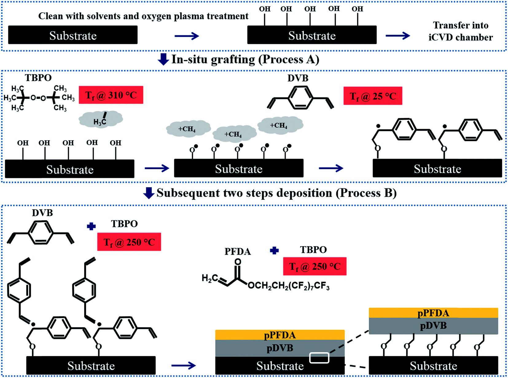 | ||
| Fig. 1 Schematics of the substrate (silicon or steel) preparation, the in situ linker-free grafting (process A), and the subsequent two-step polymer deposition (process B). Initial substrate cleaning with solvents and subsequent plasma treatment results in enhanced presence of hydroxyl groups required for in situ grafting in process A. In process A, methyl radicals were produced through exposing TBPO to the filament arrays kept at filament temperature (Tf = 310 °C). This resulted in creation of free electrons via an H-abstraction process and enabled the vinyl groups in the DVB monomer to be covalently bonded to the substrate. The radicals formed during process A provided anchoring points for the DVB monomer to react and be covalently bonded to the substrate during process B. Immediately after DVB polymerization, the TBPO and the monomer flow rate are halted to allow the retention of pendant vinyl bonds on the underlying pDVB network for covalent bonding to the subsequent PFDA polymerized top coat. The final film is a linker-free grafted bilayer pDVB/pPFDA polymeric network (BL). | ||
After surface activation, the unreacted TBPO and residual methyl radicals were evacuated by pumping the reactor down to a base pressure of less than 5 mTorr. Immediately following the TBPO treatment and without breaking vacuum, divinylbenzene (DVB) monomer was introduced to the reactor with a total pressure of 800 mTorr and without filament heating (Tf = 25 °C) while the substrate was kept at Ts = 20 °C. The vinyl bonds in the DVB monomer reacts with the activated surface sites and results in direct grafting of the monomer to the substrate while retaining a free electron for future covalent linking to deposited films. The in situ grafting in process A was repeated once to ensure good surface coverage of grafting sites.
In process B, DVB, N2, and TBPO were introduced simultaneously to the low pressure reactor similar to the traditional iCVD41 polymerization process while the filament and the substrate were kept at Tf = 250 °C and Ts = 30 °C, respectively. This resulted in deposition of a very densely cross-linked DVB polymer (pDVB) with the desired thickness (in the range of 200 nm–1 μm). Following this step, the flow of the precursors (DVB and N2) and the initiator (TBPO) was stopped and the chamber was pumped down to base pressure while the filament was immediately cooled to room temperature. This is in contrast to conventional iCVD polymerization protocols in which the filament is kept at elevated temperature even after stopping the flow of precursors in order to allow polymerization of residual unreacted monomers and formation of a capping layer on the top of the deposited polymer network without presence of any unreacted bonds. Here, we intentionally promote the presence of unreacted vinyl bonds at the surface of the deposited pDVB polymer network to serve as adhesion promoters for the subsequent deposition of a second much-thinner polymeric network composed of poly-perfluorodecylacrylate, poly-(1H,1H,2H,2H-perfluorodecylacrylate) (pPFDA). A thin layer of pPFDA (either 10 or 40 nm thick) which serves as the fluorine-rich surface layer was deposited on the top of the densely cross-linked pDVB network in a manner similar to the methods previously reported36,37 to provide the desired hydrophobic characteristics of the final bilayer surface coating.
Ultimately, a linker-free grafted bilayer of pDVB/pPFDA (abbreviated by the term BL) was obtained. We report results for both flat silicon wafer (BL on Si) and rough steel (BL on steel) substrates. Fourier transform infrared spectroscopy (FTIR) was performed on the polymer bilayer and confirmed successful deposition of both pPFDA and pDVB components through the presence of bands corresponding to carbonyl, carbon–fluorine bonds, and phenyl groups in the FTIR spectra (Fig. S2, ESI†).38 In addition, X-ray photoelectron spectroscopy was performed and confirmed the presence of fluorine groups in the bilayer films. The survey spectra showed the most prominent peaks to be C1s, O1s, and F1s with atomic percentages of 39.6, 5.1, and 55.3 which are in agreement with the theoretical values for the pPFDA (Fig. S3, ESI†).42–44 High resolution XPS spectra of F1s and C1s binding energy were also acquired. Atomic percentages of 54.30 and 7.02 were obtained for –CF2– and CF3 groups from the C1s high resolution spectra which indicates that the structure of the monomer unit, including that of the functional pendant group, is completely maintained during iCVD polymerization (Fig. S3 and Table S1, ESI†).
Scanning electron microscopy with energy dispersive X-ray spectrometer, SEM-EDS (JEOL 6010LA) was applied to verify the FTIR and XPS results. SEM-EDS micrograph and maps of distribution of elements indicates that the film is uniformly rich in fluorine and carbon over large areas (Fig. S4, ESI†).
A major concern for developing effective icephobic coatings is achieving the necessary mechanical properties that are required for industrial applications.7 To this end, the elastic modulus and hardness of the deposited polymer films were measured using a nanomechanical tester (Nanovea, M1 P-Nano/AFM) in indentation mode, and the adhesion of the bilayer polymer networks to the substrate was also examined qualitatively using its nanoscratch testing mode. The mechanical properties of the BL polymer film were measured and compared with traditional iCVD polymer coatings deposited using methods reported earlier.36–38,41
For nanoindentation, the indenter tip was driven into a specific site of the polymer film to be tested, by applying an increasing normal load at a loading rate of 0.8 mN min−1 until reaching a maximum load, Pmax = 0.38 mN. After reaching this preset maximum value, the normal load was held constant for various periods of time (creep durations of between 5–60 seconds) until the desired load-penetration curve was obtained. The resulting load-penetration curves provide data specific to the mechanical nature of the material under examination (Fig. 2a) and enable extraction of the film's modulus through a linear fit to the load-penetration curve during unloading (Fig. S5, ESI†). The hardness and elastic modulus of the thin cross-linked polymer bilayers were calculated from load-penetration curves using the ASTM E2546 standard. The hardness, H, was determined from the maximum load, Pmax, and the projected contact area, A(hc), at the critical indentation height, hc, corresponding to:
 | (1) |
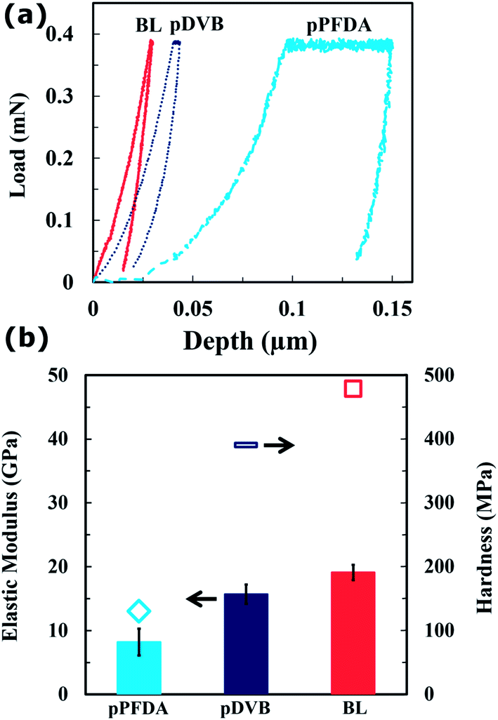 | ||
| Fig. 2 (a) Load vs. depth curve and (b) elastic modulus and hardness of the pPFDA, pDVB, and the linker-free grafted bilayer pDVB/pPFDA (BL) obtained from nanoindentation measurements. The elastic modulus and the hardness of the DVB-containing polymer films are significantly higher due to highly-cross-linked network that results from the two vinyl bonds available in the DVB monomer. | ||
The reduced elastic modulus, Er of the system, is given by:
 | (2) |
 | (3) |
Fig. 2b shows the calculated elastic modulus and hardness of the linker-free bilayer polymer film. To verify the very dense nature of the deposited bilayer polymer networks, the values of the elastic modulus and hardness were compared with those deposited using the methods based on previous reports:36–38 an ungrafted homopolymer pPFDA film37 and an ungrafted homopolymer pDVB film.41 The elastic modulus and hardness of the densely cross-linked pDVB network were E = 15.7 ± 1.5 GPa and H = 390.1 ± 4.0 MPa, respectively. These values are significantly higher than the elastic modulus (E = 8.2 ± 2.1 GPa) and the hardness (H = 131.0 ± 5.7 MPa) of the pPFDA film. The DVB monomer has two vinyl bonds whereas the flexible PFDA monomer has only one; this results in a higher cross-link density and stiffer network in the pDVB film that is deposited on the substrate, and this translates to improved mechanical properties. In addition, the DVB-containing polymers display smaller hysteresis in the load-penetration curves, reflecting lower viscoelasticity, and less penetration for a given applied load (Fig. 2a). The linker-free grafted bilayer (E = 19.1 ± 1.2 GPa and H = 479.0 ± 7.0 MPa) has slightly better mechanical properties when compared to the pDVB (Table S3, ESI†). This might be related to differences in the transient response of these bilayer polymer networks during the indentation process which arise from the presence of a compliant thin pPFDA layer on top of a stiff thick pDVB underlying substrate.18,45–47 Copolymerization and enhanced cross-linking through vacuum annealing have shown promise for improving the mechanical properties of iCVD fluoropolymers.27,28,41 For example, the elastic modulus and hardness of iCVD fluropolymers were enhanced up to four and six times, respectively, through copolymerization followed by vaccum annealing.27 This copolymerization might decrease the fluorine content in the film which is not favorable to achieve desired hydrophobicity/icephobicity. Systematic control over composition is essential for understanding the tradeoffs between mechanical properties and surface energy. The bilayer strategy reported here for the first time produces an enhanced improvement in the mechanical properties. In addition, isolating the ultrathin fluoropolymer at the top of the BL film also decreases wettability and surface energy which is essential for icephobic coatings.
Icephobic surface treatments are typically exposed to harsh environments that contain particles which can induce wear, erosion, and/or scratches on these coatings. Traditional polymer coatings usually rely on physical adsorption of the polymers onto the underlying substrates that can easily be disrupted under severe operating conditions. By contrast, iCVD polymerization enables grafting of these polymer networks to the desired substrates through strong covalent bonding. The goal is to ensure that the polymeric films are resistant to damage from scratches that result from impact by dust particles or other particulate contaminants. Nanoscratch testing is an ideal tool for qualitatively examining the adhesion between the polymers and the substrates and evaluating possible performance improvements of the linker-free grafting technique developed in this paper. A 10 μm diamond stylus tip was used at a progressive load ranging from 0 to 0.5 mN to create a 2 mm long scratch on each polymer film using a 1 mN min−1 load rate. The point at which the thin polymeric film fails by cracking is taken as the point of failure. Nanoscratch tests were performed on the ungrafted bilayer (UG-BL) film and the linker-free grafted bilayer (BL) film on both steel and silicon substrates. The surfaces were then examined through optical microscopy and scanning electron microscopy (SEM) imaging.
In Fig. 3a we show an SEM image of a nanoscratch test on the ungrafted (UG-BL) film which reveals multiple delamination events along the scratch, indicative of poor adhesion of the polymer to the substrate. In contrast, for the same load range, the scratches on the linker-free grafted bilayer polymeric films (BL) were barely discernable. The maximum load was increased to 5 mN maintaining the same scratch length, which resulted in a very high load rate of 1.238 mN min−1. Scratches created under these conditions were also examined and no observable delamination or failure in either of the polymer films could be seen in subsequent SEM images (Fig. 3b). This confirms that the reaction between DVB and surface hydroxyl groups in process A occurred during in situ grafting as shown in Fig. 1, which makes subsequent covalent bonding of the growing polymer network to the underlying substrate possible. Multiple tests (N ≥ 4) were done on each sample in order to ensure reproducibility. No failure was observed on the grafted polymer films, which is an indication of good surface coverage and uniformity of the in situ grafting mechanism. The application of a strong local skewering deformation through scratching with a sharp probe enables us to explore the adhesion strength of the polymer films with the underlying substrate.
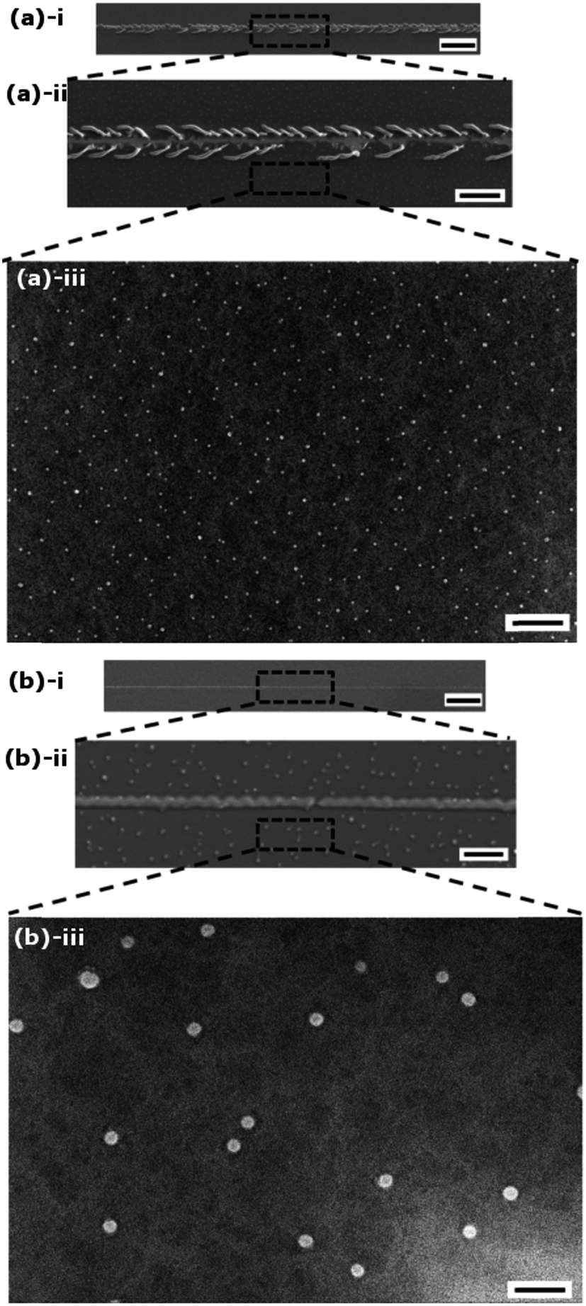 | ||
| Fig. 3 Nanoscratch testing of the bilayer films. SEM images of (a) an ungrafted bilayer pDVB/pPFDA polymer (UG-BL) and (b) linker-free grafted bilayer pDVB/pPFDA polymer film (BL). The SEM images of the ungrafted bilayer films in a(i and ii) show the presence of frequent delamination events during the nanoscratch tests, whereas no sign of scratch was observed in the SEM images of the BL film in b(i and ii). The higher magnification SEM images in a and b(iii) show additional surface features on the iCVD deposited polymer films. The scale bars represent 50 μm in (i), 20 μm in (ii), and 2 μm in (iii). | ||
Higher resolution SEM images reveal additional surface features in the linker-free grafted polymer (BL) and the ungrafted (UG-BL) coatings (Fig. 3a and b(iii)). We believe that the nodules observed in the images are formed at the end of polymer deposition by falling and deposition of the remaining precursors in the reactor. Additional optical microscopy images (Fig. S6, ESI†) show full-field images of the scratch damage that develops in the deposited polymer films both with, and without, grafting. The failure events observed are enhanced towards the end of the scratch where the applied normal loads reach their maximum. Overall, the bilayer films that are grafted to the substrate show better mechanical properties and enhanced adhesion to the substrate.
The surface morphology of the polymer films were studied by optical profilometry and atomic force microscopy (AFM) (Fig. S7, ESI†). iCVD as a conformal and substrate-independent deposition technique usually results in formation of smooth polymerized coatings. Variation in the morphology of the films deposited by iCVD on smooth substrates can be due to the polymerization recipe, the type, and the structure of the deposited polymer.37 For example; the morphology of the BL polymer with top pPFDA thickness of 10 nm deposited on a smooth silicon wafer (BL (10 nm) on Si) is Rq = 28.3 ± 3.8 nm and is slightly different than the pPFDA homopolymer (Rq = 15.5 ± 3.4 nm). It is important to note that changing the top layer pPFDA thickness to 40 nm did not result in a noticeable change in the roughness of the bilayer polymer (Rq = 34.2 ± 5.2 nm for BL (40 nm) on Si).
A linker-free grafted bilayer pDVB/pPFDA with pPFDA thickness of 10 nm and 40 nm (which we denote as BL (10 nm) on steel and BL (40 nm) on steel, respectively) were also deposited on a rough steel substrate and their surface properties were again examined with optical profilometry (Fig. S8, ESI†). An RMS roughness value of Rq = 132.5 ± 17.4 nm and Rq = 120.3 ± 22.0 nm were obtained from measurement performed over 136 μm × 102 μm area on BL (10 nm) on steel and BL (40 nm) on steel, respectively. The increase in the RMS roughness value of this polymer film when deposited on the steel (as compared to the value measured on the silicon wafer) comes from the roughness of the underlying steel substrate.
Goniometric measurements of the water contact angles (WCA) were performed to evaluate the wettability of the fluoropolymer films and changes associated with the polymer composition, thickness, and grafting mechanism. Fig. 4a shows representative droplet images captured during the advancing WCA measurements. The pDVB film is weakly hydrophobic and exhibits both low advancing (94.4° ± 2.1°) and receding (74.1° ± 2.9°) values of the WCA, whereas the pPFDA film presents both a high advancing (147.2° ± 2.4°) and high receding (127.1° ± 5.2°) WCA due to the presence of fluorine-containing groups. The linker-free grafted bilayer pDVB/pPFDA polymer with a top pPFDA thickness of ∼40 nm (BL (40 nm) on Si) resulted in higher advancing (149.1° ± 1.9°) and receding (132.0° ± 7.8°) WCA. Small differences in the measured WCAs of the pPFDA and BL (40 nm) on Si networks might be due to the differences in their surface morphology or different crystallinity of the top pPFDA layer which can arise from variations in the polymer deposition rate.36,37 BL (40 nm) was deposited on steel as well with advancing and receding WCA of 152.0° ± 2.0° and 143.2° ± 1.7°, respectively. This substantial increase in the advancing and receding contact angle is due to the enhanced surface roughness of the linker-free grafted polymer film that originates from the rough steel substrate48 (The Wenzel roughness, r, of BL (10 nm) on Si and steel is 1.36 and 1.92, respectively).
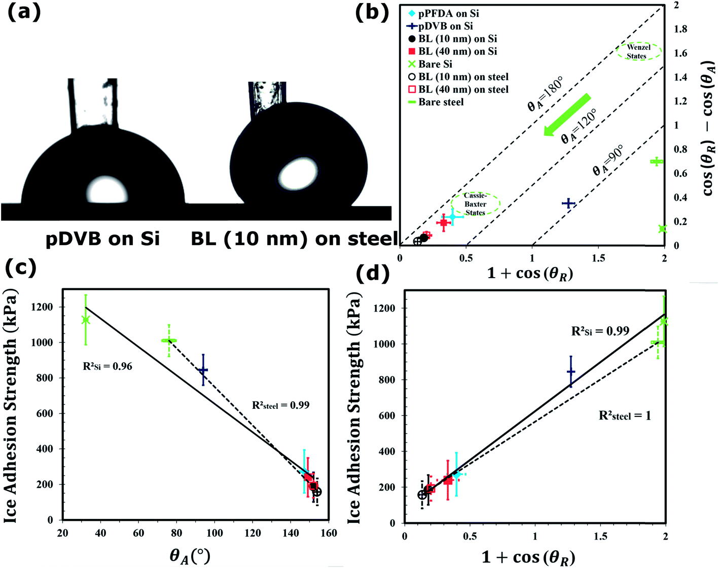 | ||
Fig. 4 (a) Representative droplet images captured during advancing water contact angle (WCA) measurements on pDVB coated silicon (left) and linker-free grafted bilayer pDVB/pPFDA polymer with pPFDA thickness of 10 nm (BL (10 nm)) coated steel (right). The images show that the advancing WCA on the polymer films increases through incorporation of a thin fluorine containing polymer. (b) Measurements of the water contact angle and contact angle hysteresis represented in the form of the dimensionless work of adhesion (1 + cos![[thin space (1/6-em)]](https://www.rsc.org/images/entities/char_2009.gif) θR) vs. contact angle hysteresis (cosθR − cosθA). High WCA hysteresis and low receding WCA are representative of the Wenzel state, while high receding WCA and low WCA hysteresis are signatures of the Cassie–Baxter state. Most of the deposited polymer films that are studied in this work exhibit features of the Cassie–Baxter state that are favorable for icephobic surfaces. The average strength of ice adhesion on two different substrates (silicon and steel) coated with polymeric bilayers plotted vs. the advancing WCA in (c) and the work of adhesion in (d). Both silicon and steel substrates coated with a linker-free bilayer coating (BL (10 nm)) exhibited more than six-fold reduction in the average strength of ice adhesion. A linear fit through the data in (d) shows an excellent correlation of RSi2 = 0.99 and Rsteel2 = 1. θR) vs. contact angle hysteresis (cosθR − cosθA). High WCA hysteresis and low receding WCA are representative of the Wenzel state, while high receding WCA and low WCA hysteresis are signatures of the Cassie–Baxter state. Most of the deposited polymer films that are studied in this work exhibit features of the Cassie–Baxter state that are favorable for icephobic surfaces. The average strength of ice adhesion on two different substrates (silicon and steel) coated with polymeric bilayers plotted vs. the advancing WCA in (c) and the work of adhesion in (d). Both silicon and steel substrates coated with a linker-free bilayer coating (BL (10 nm)) exhibited more than six-fold reduction in the average strength of ice adhesion. A linear fit through the data in (d) shows an excellent correlation of RSi2 = 0.99 and Rsteel2 = 1. | ||
The linker-free grafted bilayer film (pDVB/pPFDA) with a smaller pPFDA top layer thickness of approximately 10 nm was also deposited on both silicon (BL (10 nm) on Si) and steel (BL (10 nm) on steel) substrates and resulted in an increase in the advancing WCA (152.0° ± 2.1° on silicon and 154.0° ± 1.1° on steel) and receding WCA (145.0° ± 1.8° on silicon and 150.3° ± 1.6° on steel) (Fig. S9, ESI†). While, there was no significant variation in advancing WCA, a significant decrease in WCA hysteresis was observed. It has been shown that the presence of the highly-cross-linked pDVB network underneath a thin pPFDA film can prevent inward reorientation of its fluorine groups when exposed to water and this results in the lower WCA hysteresis that is observed macroscopically (Fig. S1, ESI†).38
The wettability and motion of liquid droplets on surfaces involves both shear and tensile phenomena.33,34 A sessile droplet on a tilted surface experiences a shear force which is a function of the WCA hysteresis. As discussed by Furmidge32 in 1962 a force balance immediately prior to droplet sliding gives:
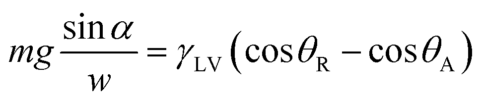 | (4) |
On the other hand, the tensile force required to detach a droplet from the surface can be considered as a measure of the tensile hydrophobicity of a surface. This is related to the work of adhesion between a liquid droplet and the underlying substrate and can be calculated from the Young–Dupré equation as suggested by Gao and McCarthy:33,34
| Wadh = γLV(1 + cosθR) | (5) |
In summary, low WCA hysteresis corresponds to low resistance to shear modes of loading at the solid–water interface while a high receding WCA corresponds to low pull-off forces under tensile (normal) loading conditions. To reflect these different measures of surface hydrophobicity and their differing functional dependences on the advancing and receding contact angles, we present our wettability data by plotting our goniometric measurements as (1 + cosθR) vs. (cosθR − cosθA) as shown in Fig. 4b. In this coordinate representation, lines of constant advancing contact angle are inclined at 45°. High WCA hysteresis and low receding WCA are representative of Wenzel-like49 states, while high receding WCA and low WCA hysteresis are the signature of Cassie–Baxter-like50 states.
Fig. 4b shows that most of the iCVD polymer films deposited in this work promote Cassie–Baxter like states that have high receding contact angles and very low contact angle hysteresis and are therefore favorable for creating icephobic surfaces. In addition, polymer films deposited on rough steel substrates with only 10 nm pPFDA top layer further promote Cassie–Baxter state.
Next, the strength of ice adhesion to the substrates coated with the iCVD polymer films was measured using a custom-built set up (Fig. S10, ESI†). Plastic cuvettes were filled with DI water and allowed to freeze at −15 °C under nitrogen atmosphere for 2 h on both polymer-coated and bare substrates (steel and silicon). A representative video showing the formation of ice and propagation of the solidification front inside the cuvette is provided in the video S1 and Fig. S10, ESI†. The lateral force required to de-adhere frozen cuvettes was recorded and converted into a measure of the shear strength of ice adhesion by dividing over the cuvette area. A sample image showing a frozen cuvette after de-adhesion from a substrate is taken (Fig. S10, ESI†). The measurements were performed on twenty samples of each type and subsequently averaged. Sample-to-sample variations in the measured adhesion strengths can be large due to the dominant role of local flaws in this failure test and variations in the nature of the ice formed at the interface with the substrate. Fig. 4c and d show the measured average strength of ice adhesion as a function of the advancing WCA, θA, and the scaled work of adhesion, (1 + cosθR), respectively. The average strength of ice adhesion was linearly reduced by a decrease in the work of adhesion (RSi2 = 0.99 and Rsteel2 = 1.0, Fig. 4d) and an increase in the advancing contact angle θA (RSi2 = 0.96 and Rsteel2 = 0.99, Fig. 4c).51 Silicon substrates coated with a linker-free bilayer of fluorinated polymer (BL (10 nm)) resulted in ice adhesion strength of 185.3 ± 83.7 kPa, which is more than a six-fold reduction when compared to the bare silicon substrate. Similarly, more than a six-fold decrease in the average strength of ice adhesion was observed on steel substrates (dashed lines in Fig. 4c and d) coated with a similar bilayer (BL (10 nm)).
Good correlation between the measured hydrophobicity of liquid water droplets placed on the deposited polymer films and their measured icephobic behavior is observed. These results confirm that surfaces with both high advancing and receding water contact angles (and low WCA hysteresis) are optimal for reducing the strength of ice adhesion. The reduction in the strength of ice adhesion reported in this work is higher than those values reported elsewhere for soft fluorinated polymer coatings.4,9,12,52–57 Lubricant-impregnated textured surfaces have resulted in an order of magnitude reduction in ice/frost adhesion. For example, Kim et al. have shown in a recent study that the ice adhesion strength on aluminum surfaces can reduce from 1360 ± 210 kPa to 15.6 ± 3.6 kPa by liquid-infused porous where an ultrasmooth low hysteresis lubricant overlayer was maintained by infusing a water-immiscible liquid into a nanostructured surface. However, the stability of these liquids can be a major issue due to significant changes of evaporation over the time. In this work, the high modulus and stiffness of the cross-linked polymer networks that are deposited by the iCVD process provide greatly enhanced mechanical resistance to scratching and indentation processes that are characteristic of industrial applications.
One of the major concerns for developing effective icephobic coatings is achieving the necessary durability that is required for industrial applications. The surface properties of most polymer coatings degrade after repeated cycles of ice formation and detachment. To demonstrate the resilience of the coatings, we characterized the wettability and icephobic properties of the linker-free coatings after two repeated cycles of ice formation and detachment. To this end, substrates that were used for initial ice formation and adhesion tests were re-used for another set of ice formation and adhesion strength measurements.
The ice adhesion strength for a bilayer film on silicon (BL (10 nm) on Si) and a bilayer film on steel (BL (10 nm) on steel) re-used substrates were 208.2 ± 105.0 kPa and 171.5 ± 92.7 kPa, respectively, which are within the same range of adhesion values obtained on as-deposited coatings (185.3 ± 83.7 kPa for BL (10 nm) on Si and 158.5 ± 76.0 kPa for BL (10 nm) on steel). Advancing and receding contact angles of water droplets were re-measured after ice adhesion test on polymer coatings. The measured values were also within the same range as those obtained from measurements on the as-deposited samples (Table S2, ESI†). In future tests the performance of these iCVD polymer coatings will be studied under cyclic icing/deicing treatment and their durability evaluated after long-term contact with aqueous media and high humidity.7,58
Conclusions
In conclusion, we have developed a unique method for the creation of thin cross-linked bilayer films via a solvent-free and substrate-independent iCVD deposition technique that results in deposition of a thin and conformal covalently cross-linked polymeric network. Additionally, we demonstrate, for the first time, linker-free grafting of an iCVD polymer network to rough steel substrates. Stiff fluorinated polymeric coatings with a high WCA and low WCA hysteresis can be created. The in situ linker-free grafting significantly enhances the adhesion of the polymer film to the underlying substrate, increasing the potential for industrial deployment of this technology. The linker-free grafted bilayer (BL) coatings show enhanced mechanical properties and resistance to damage from scratching due to the high cross-link density of the polymer network. The strength of ice adhesion was reduced by more than six-fold when substrates were coated with these fluorinated bilayer films as a result of the low surface energy and smoothness of the iCVD coatings (Table S3, ESI†). The measured values of the ice adhesion strength was found to correlate well with the practical work of adhesion (i.e. Wadh = γLV(1 + cosθR)) for liquid water droplets on the surface. The limited segmental mobility of the thin upper layer of highly-cross-linked fluorinated chains prevents local remodeling of the surface when it is in contact with liquid water. This results in low energy surfaces with very low values of the contact angle hysteresis and comitantly low values of the ice adhesion strength.
Acknowledgements
The authors gratefully acknowledge support from the Chevron-MIT Energy Initiative program and valuable conversations with Dr Matthew R. Walsh.Notes and references
- J. L. Laforte, M. A. Allaire and J. Laflamme, Atmos. Res., 1998, 46, 143–158 CrossRef.
- H. Saito, K. Takai, H. Takazawa and G. Yamauchi, Mater. Sci. Res. Int., 1997, 3, 216–219 CAS.
- R. W. Andrews, A. Pollard and J. M. Pearce, Sol. Energy Mater. Sol. Cells, 2013, 113, 71–78 CrossRef CAS PubMed.
- S. B. Subramanyam, K. Rykaczewski and K. K. Varanasi, Langmuir, 2013, 29, 13414–13418 CrossRef CAS PubMed.
- S. Frankenstein and A. M. Tuthill, J. Cold Reg. Eng., 2002, 16, 83–96 CrossRef.
- N. Dalili, A. Edrisy and R. Carriveau, Renewable Sustainable Energy Rev., 2009, 13, 428–438 CrossRef PubMed.
- R. Menini, Z. Ghalmi and M. Farzaneh, Cold Reg. Sci. Technol., 2011, 65, 65–69 CrossRef PubMed.
- P. K. Dutta, C. C. Ryerson and C. Pergantis, in Materials for Space Applications, ed. M. Chipara, D. L. Edwards, R. S. Benson and S. Phillips, Materials Research Society, Warrendale, 2005, vol. 851, pp. 563–574 Search PubMed.
- P. Kim, T. S. Wong, J. Alvarenga, M. J. Kreder, W. E. Adorno-Martinez and J. Aizenberg, ACS Nano, 2012, 6, 6569–6577 CrossRef CAS PubMed.
- J. X. Lai, C. Liu and C. B. Gong, in Frontiers of Green Building, Materials and Civil Engineering, ed. D. Sun, W. P. Sung and R. Chen, Trans Tech Publications Ltd, Stafa-Zurich, 2011, vol. 71–78, Pts 1–8, pp. 1865–1869 Search PubMed.
- C. Laforte and J. L. Laforte, J. Adhes. Sci. Technol., 2012, 26, 603–620 CAS.
- A. J. Meuler, J. D. Smith, K. K. Varanasi, J. M. Mabry, G. H. McKinley and R. E. Cohen, ACS Appl. Mater. Interfaces, 2010, 2, 3100–3110 CAS.
- R. M. Dou, J. Chen, Y. F. Zhang, X. P. Wang, D. P. Cui, Y. L. Song, L. Jiang and J. J. Wang, ACS Appl. Mater. Interfaces, 2014, 6, 6998–7003 CAS.
- P. Guo, Y. M. Zheng, M. X. Wen, C. Song, Y. C. Lin and L. Jiang, Adv. Mater., 2012, 24, 2642–2648 CrossRef CAS PubMed.
- Y. He, C. Y. Jiang, X. B. Cao, J. Chen, W. Tian and W. Z. Yuan, Appl. Surf. Sci., 2014, 305, 589–595 CrossRef CAS PubMed.
- H. Li, Y. H. Zhao and X. Y. Yuan, Prog. Chem., 2012, 24, 2087–2096 CAS.
- J. Lv, Y. Song, L. Jiang and J. Wang, ACS Nano, 2014, 8, 3152–3169 CrossRef CAS PubMed.
- M. Pustan, C. Dudescu, C. Birleanu and Z. Rymuza, Int. J. Mater. Res., 2013, 104, 408–414 CrossRef CAS.
- M. Ruan, W. Li, B. S. Wang, B. W. Deng, F. M. Ma and Z. L. Yu, Langmuir, 2013, 29, 8482–8491 CrossRef CAS PubMed.
- M. Susoff, K. Siegmann, C. Pfaffenroth and M. Hirayama, Appl. Surf. Sci., 2013, 282, 870–879 CrossRef CAS PubMed.
- R. Yang, T. Buonassisi and K. K. Gleason, Adv. Mater., 2013, 25, 2078–2083 CrossRef CAS PubMed.
- X. L. Zhan, Y. D. Yan, Q. H. Zhang and F. Q. Chen, J. Mater. Chem. A, 2014, 2, 9390–9399 CAS.
- W. Li, X. Zhang, J. Yang and F. Miao, J. Colloid Interface Sci., 2013, 410, 165–171 CrossRef CAS PubMed.
- L. F. Mobarakeh, R. Jafari and M. Farzaneh, Appl. Surf. Sci., 2013, 284, 459–463 CrossRef PubMed.
- A. M. Coclite, R. M. Howden, D. C. Borrelli, C. D. Petruczok, R. Yang, J. L. Yague, A. Ugur, N. Chen, S. Lee, W. J. Jo, A. D. Liu, X. X. Wang and K. K. Gleason, Adv. Mater., 2013, 25, 5392–5422 CrossRef CAS PubMed.
- G. Ozaydin-Ince, A. M. Coclite and K. K. Gleason, Rep. Prog. Phys., 2012, 75, 016501 CrossRef PubMed.
- Y. Mao and K. K. Gleason, Macromolecules, 2006, 39, 3895–3900 CrossRef CAS.
- J. J. Xu, A. Asatekin and K. K. Gleason, Adv. Mater., 2012, 24, 3692–3696 CrossRef CAS PubMed.
- S. A. Kulinich and M. Farzaneh, Langmuir, 2009, 25, 8854–8856 CrossRef CAS PubMed.
- H. Murase, K. Nanishi, H. Kogure, T. Fujibayashi, K. Tamura and N. Haruta, J. Appl. Polym. Sci., 1994, 54, 2051–2062 CrossRef CAS.
- C. Della Volpe, S. Siboni and M. Morra, Langmuir, 2002, 18, 1441–1444 CrossRef CAS.
- C. G. Furmidge, J. Colloid Sci., 1962, 17, 309 CrossRef CAS.
- L. C. Gao and T. J. McCarthy, Langmuir, 2008, 24, 9183–9188 CrossRef CAS PubMed.
- L. C. Gao and T. J. McCarthy, Langmuir, 2009, 25, 14105–14115 CrossRef CAS PubMed.
- E. J. De Souza, L. C. Gao, T. J. McCarthy, E. Arzt and A. J. Crosby, Langmuir, 2008, 24, 1391–1396 CrossRef CAS PubMed.
- A. M. Coclite, Y. J. Shi and K. K. Gleason, Adv. Mater., 2012, 24, 4534–4539 CrossRef CAS PubMed.
- A. M. Coclite, Y. J. Shi and K. K. Gleason, Adv. Funct. Mater., 2012, 22, 2167–2176 CrossRef CAS.
- J. L. Yague and K. K. Gleason, Macromolecules, 2013, 46, 6548–6554 CrossRef CAS.
- H. K. Yasuda, Plasma Polymerization, Academic Press, Inc., Orlando, FI, 1985 Search PubMed.
- G. Ozaydin-Ince and K. K. Gleason, J. Vac. Sci. Technol., A, 2009, 27, 1135–1143 CAS.
- C. D. Petruczok, R. Yang and K. K. Gleason, Macromolecules, 2013, 46, 1832–1840 CrossRef CAS.
- V. Kumar, J. Pulpytel and F. Arefi-Khonsari, Plasma Processes Polym., 2010, 7, 939–950 CrossRef CAS.
- G. Beasmon and D. Briggs, High Resolution XPS of Organic Polymers: The Scienta ESCA300 Database, John Wiley & Sons, 1992 Search PubMed.
- M. Gupta and K. K. Gleason, Langmuir, 2006, 22, 10047–10052 CrossRef CAS PubMed.
- J. W. Hutchinson, Philos. Trans. R. Soc., A, 2013, 371, 20120422 CrossRef PubMed.
- J. Zang, X. Zhao, Y. Cao and J. W. Hutchinson, J. Mech. Phys. Solids, 2012, 60, 1265–1279 CrossRef CAS PubMed.
- R. Jayachandran, M. C. Boyce and A. S. Argon, J. Adhes. Sci. Technol., 1993, 7, 813–836 CrossRef CAS PubMed.
- A. Hennig, K. Grundke, R. Frenzel and M. Stamm, Tenside, Surfactants, Deterg., 2002, 39, 243–246 Search PubMed.
- A. Marmur, Langmuir, 2003, 19, 8343–8348 CrossRef CAS.
- A. B. D. Cassie and S. Baxter, Trans. Faraday Soc., 1944, 40, 0546–0550 RSC.
- S. A. Kulinich and M. Farzaneh, Appl. Surf. Sci., 2009, 255, 8153–8157 CrossRef CAS PubMed.
- A. Davis, Y. H. Yeong, A. Steele, I. S. Bayer and E. Loth, ACS Appl. Mater. Interfaces, 2014, 6, 9272–9279 CAS.
- S. T. Zhang, H. Wang and L. Wang, in New Materials, Applications and Processes, ed. J. M. Zeng, Y. H. Kim and Y. F. Chen, Trans Tech Publications Ltd, Stafa-Zurich, 2012, vol. 399–401, Pts 1–3, pp. 2044–2048 Search PubMed.
- R. J. Cano, E. S. Weiser, T. M. Smith, S. Trigwell, L. A. Curtis and D. Drewry, J. Adhes. Sci. Technol., 2012, 26, 621–649 CAS.
- S. Q. Yang, Q. A. Xia, L. Zhu, J. A. Xue, Q. J. Wang and Q. M. Chen, Appl. Surf. Sci., 2011, 257, 4956–4962 CrossRef CAS PubMed.
- V. F. Petrenko and S. Peng, Can. J. Phys., 2003, 81, 387–393 CrossRef CAS PubMed.
- V. K. Croutch and R. A. Hartley, J. Coat. Technol., 1992, 64, 41–53 CAS.
- L. B. Boinovich, A. M. Emelyanenko, V. K. Ivanov and A. S. Pashinin, ACS Appl. Mater. Interfaces, 2013, 5, 2549–2554 CAS.
Footnote |
| † Electronic supplementary information (ESI) available. See DOI: 10.1039/c4mh00162a |
| This journal is © The Royal Society of Chemistry 2015 |