Research highlights: surface-based microfluidic control
Oladunni
Adeyiga
ab,
Soroush
Kahkeshani
a,
Petra
Paiè
ac and
Dino
Di Carlo
*ade
aDepartment of Bioengineering, University of California, Los Angeles, CA 90095, USA. E-mail: dicarlo@ucla.edu
bDivision of Infectious Diseases, Department of Medicine, David Geffen School of Medicine, University of California, Los Angeles, CA 90095, USA
cDipartimento di Fisica, Politecnico di Milano, Piazza Leonardo da Vinci 32, 20133 Milano, Italy
dCalifornia NanoSystems Institute, Los Angeles, California, USA
eJonsson Comprehensive Cancer Center, Los Angeles, California, USA
First published on 22nd June 2015
Abstract
Microfluidic systems are often dominated by their surfaces because of the high surface area to volume ratios in microchannel flows or drop-based systems. Here we highlight recent work on engineering and exploiting surface effects to control the formation and motion of microdrops. We highlight work using precisely microstructured wetting surfaces to repel all manner of liquids even when the liquid–air surface tension is low. In a second paper, selective capillary filling and draining is used to pattern liquid and cell-laden gels for 3D culture. A final paper making use of vapor-driven surface tension effects to drive the motion of drop ensembles is also examined, exploring a new mechanism for drop control – including motion and merging. Surface-driven motion and patterning has been a widely successful area in microfluidics (e.g. electrowetting or patterned self-assembled monolayers) and recent work is extending into new directions that, once well-understood, should enable new applications.
One microstructure to repel them all
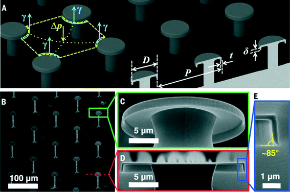
Controlling the wetting (or non-wetting) of a surface can have wide applications in preventing biofouling, maintaining isolated droplets, reducing drag, or self-cleaning. Two important factors for preventing wetting are the surface tension of a fluid in air, and fluid–solid interfacial tension (wettability). For water or an aqueous solution on a hydrophobic material, a simple microstructure can direct the liquid to a suspended (balled-up) state. However, for oil and organic solvents on a hydrophobic material, more complex structural surfaces are needed. Still for low surface tension fluids below 15 to 20 mN m−1 repellency (or superrepellency) had not been previously achieved.Liu and Kim1 designed an array of doubly reentrant structures consisting of microscale posts with nanoscale vertical overhangs to achieve a superomniphobic surface (Fig. 1). Posts were chosen over ridges or holes to minimize liquid–solid contact fraction more easily, and a doubly reentrant structure prevents wetting even for highly wetting or low surface tension fluids. Also, the post array allows the air underneath the droplet to remain connected to the atmosphere so that the liquid is suspended only by surface tension and is not assisted by the pressure of the trapped air. They chose to form the surface structures from SiO2 for the following two reasons: first, clean SiO2 is highly wetted by most liquids. Second, Si micromachining provides sophisticated equipment and techniques to process SiO2.
To evaluate the liquid repellency, they chose 14 different liquids including water, ionic liquid, acid, oils, and numerous polar or nonpolar organic or fluorinated solvents with surface tensions ranging from 72.8 mN m−1 (i.e., water) to the lowest known value of 10 mN m−1 (i.e., FC-72). Their structured SiO2 surface successfully suspended and repelled all of the tested liquids, beading them into droplets, and letting them roll around; that is, behaving superomniphobic in air.
In addition to repelling all 14 liquids, their superomniphobic surfaces are also expected to sustain static and dynamic pressures better than the existing superhydrophobic and superoleophobic surfaces. The doubly reentrant structures allow droplets to bounce on even extremely sparse posts (i.e., tens of micrometers of pitch and a solid fraction of only ~5%). The same superomniphobicity is further confirmed with identical surfaces with varied interfacial tensions (a metal and a polymer).
Unaffected by the surface chemistry, the superomniphobic SiO2 surface also demonstrated prolonged repellency to biological fluids (such as sheep serum or blood), whereas a regular superhydrophobic surface lost the repellency.
In conclusion, the proposed superrepellency depends only on physical attributes. They show how roughness alone, if made of a specific doubly reentrant structure that enables very low liquid–solid contact fraction, can render the surface of any material superrepellent.
Capillarity-guided micropatterning
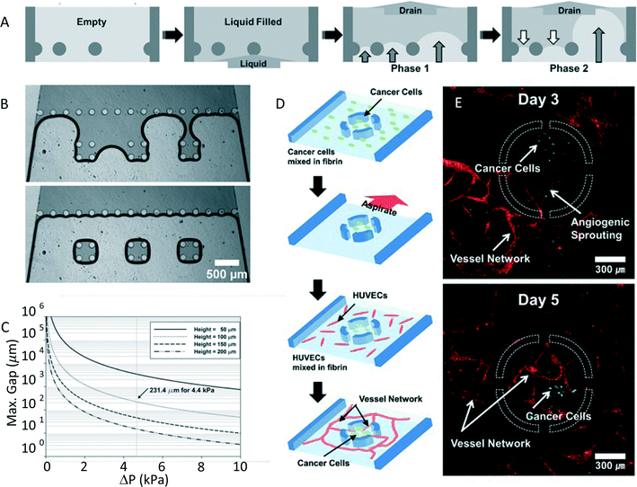
The capability to pattern cells is important for many biological applications, ranging from the capacity to measure cellular properties in well-controlled conditions to the development of in vitro platforms for drug screening. For this reason there has been an increasing interest in this topic. Microcontact printing2 and micromolding in capillaries3 are two of the most used techniques for cell patterning based on a soft lithography approach. These methods, exploiting the selective attachment of cells to a protein or extracellular matrix substrate, can produce small and precise patterns. Multicellular patterning or co-cultures, however, can be difficult to achieve with this approach. Kang et al.4 show an innovative method for rapid patterning based on controlled fluid draining in a microfluidic device named capillarity guided patterning (CGP). In this work they demonstrate a fast and easy technique allowing them to obtain patterns of liquids with different shapes and dimensions. A wide range of biological applications are also envisaged.This technique exploits the dynamics of a liquid meniscus during the drain phase of a microchannel that contains posts. The liquid air interface, that meets these structures, creates a set of menisci. Their shape depends on the surface tension of the liquid and on the pressure difference between liquid and air. The evolution of these menisci, instead, is shown to be dependent on the distance between the posts. In particular they explain through simple geometrical considerations how after a first phase in which all menisci bulge into the liquid region, only the menisci with the larger distance between the posts further develop, while all the others retreat (Fig. 2A). This phenomenon can be used to trap liquid in regions of closely packed posts; as reported in Fig. 2B, where we can observe the formation of liquid patterns in three separated groups of close posts after the draining. This principle allows one to also obtain more complicated liquid patterns in microfluidic channels, by just properly choosing the geometry of the posts. Nevertheless, not all configurations are allowed with this approach. In fact, as Kang et al. underline, the capability to efficiently trap liquid depends on the surface tension, which should be dominant over inertia. The analysis of the dimensionless Weber number permitted study of the value of the maximum gap between posts that still allows the surface tension to be dominant, since it provides the relative importance between inertia and surface tension. Fig. 2C shows the calculated maximum value of the gap between the posts as a function of the difference in pressure (ΔP). As expected, for increasing ΔP, and consequently the inertial forces, the permitted gap between posts should decrease.
As a proof of concept they demonstrated the efficient use of CGP in biological applications that require cell patterning. In particular, this technique has been used to efficiently mimic angiogenesis, which is a process through which new blood vessels form. This is a 3D process that involves cell–cell and cell–ECM interactions, which is difficult to reproduce in a simple 2D culture platform. As reported in Fig. 2D, cancer cells (U87MG) were patterned in close proximity to HUVEC cells, to monitor the growth of the blood vessel network. First the cancer cells were trapped through CGP in a circular environment with four openings. Subsequently, the device was filled with HUVECs in a fibrin matrix, surrounding the previously localized cancer cells. Fluorescence images of the device (Fig. 2E) show the formation of blood vessels and their penetration into the circular trap area, under the influence of U87MG cells.
In conclusion, the authors have developed a simple and robust nonlithographic patterning method, that exploits the presence of strategically placed microstructures in a microchannel to trap liquid in a desired pattern. The study of the dynamics of the liquid–air interface has allowed optimization of this process, giving rise to a technique that appears to be extremely versatile and capable of obtaining patterns of different liquid shape and dimension. Furthermore, the authors demonstrate as a proof of principle some possible biological applications of this device, like the capability to simply reproduce an in vitro model for angiogenesis.
Droplets chasing droplets
Microfluidic techniques are commonly used in the formation of droplets to confine reactions and concentrate molecules into defined volumes, enabling a range of applications. A range of microfluidic droplet generation and manipulation approaches have been demonstrated, using enclosed or open channels (e.g. electrowetting, or digital microfluidics). N. J. Cira and co-authors5 look at how the droplets of a two-component liquid mixture interact via vapour-mediated sensing, and how this sensing impacts droplet motility. In understanding this phenomenon, they demonstrate some passive manipulation techniques.To study this, the authors use a water and propylene glycol (PG) liquid mixture, which were chosen because they are miscible liquids. In addition, their difference in volatility allowed the authors to perform a detailed study of the mechanisms of droplet formation and stabilization (whereby the formed droplet is prevented from spreading into a thin film covering the surface), and postulate how surface tension and vapour pressure are involved in this process. They first observe that when placed on corona-discharge-cleaned glass slides (a high surface energy substrate), this two liquid mixture will form droplets with apparent contact angles (θapp). Furthermore, θapp varies with changes in relative humidity. This likely indicates that local evaporation would affect the local contact angle and gradients in contact angle. Additionally, by assuming a sharp transition of surface tension between the bulk droplet (γLV,droplet) and the surrounding thin film, they construct a simple model to test their proposed mechanism of droplet stabilization, γLV,droplet![[thin space (1/6-em)]](https://www.rsc.org/images/entities/char_2009.gif) cos(θapp) = γLV,film.
cos(θapp) = γLV,film.
Interestingly, when two droplets of the PG–water liquid mixture were deposited on a glass slide, they moved toward one another; this effect remained over a wide range of liquid mixture concentrations, and even across a break in the glass slide. The authors conclude that this effect is mediated by vapour and propose a mathematical model to describe the relationship for the expected distance L between identical droplets as a function of time. They first derive an expression to describe the net force (Fnet) acting on each droplet:
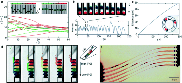
Finally, the authors used what they learned by studying these interactions to create several different droplet based devices which include: a spontaneous droplet aligner, a vertical droplet oscillator, a circular droplet chasing device, a surface tension sorter, and a flexible substrate for droplet chasing (Fig. 3). These so-called self-fueled surface-tension-driven fluidic machines were fashioned out of everyday materials (food coloring, glass slides, and permanent Sharpie® markers). They also introduce devices that consist of parallel glass slides to investigate how long-range droplet interactions can be exploited for various applications. Overall, this work helps to inform our understanding of the physical behavior of two-component miscible liquid droplets on open high energy substrates, where gradients in humidity play a role. It also provides a framework for how we can use this understanding to develop simple devices to manipulate droplets. Further work will be needed to determine for what applications these systems are best suited.
References
- T. L. Liu and C. J. Kim, Science, 2014, 346, 1096–1100 CrossRef CAS PubMed.
- J. L. Wilbur, A. Kumar, H. A. Biebuyck, E. Kim and G. M. Whitesides, Nanotechnology, 1996, 7, 452 CrossRef CAS.
- J. Hong, J. B. Edel and A. J. de Mello, Drug Discovery Today, 2009, 14, 134 CrossRef CAS PubMed.
- M. Kang, W. Park, S. Na, S. M. Paik, H. Lee, H. Lee, J. W. Park, H. Y. Kim and N. L. Jeon, Small, 2015, 11, 2789–2797 CrossRef CAS PubMed.
- N. J. Cira, A. Benusiglio and M. Prakash, Nature, 2015, 519, 446–450 CrossRef CAS PubMed.
| This journal is © The Royal Society of Chemistry 2015 |


