
 Open Access Article
 This Open Access Article is licensed under a Creative Commons Attribution-Non Commercial 3.0 Unported Licence
Applications of three-dimensional (3D) printing for microswimmers and bio-hybrid robotics
M. M.
Stanton
a,
C.
Trichet-Paredes
a and
S.
Sánchez
*abc
aMax-Planck Institute for Intelligent Systems, Heisenbergstr. 3, 70569 Stuttgart, Germany. E-mail: sanchez@is.mpg.de; ssanchez@ibecbarcelona.eu
bInstitute for Bioengineering of Catalonia (IBEC), Baldiri I Reixac 10-12, 08028 Barcelona, Spain
cInstitució Catalana de Recerca i Estudis Avançats (ICREA), Psg. Lluís Companys, 23, 08010 Barcelona, Spain
First published on 29th January 2015
Abstract
This article will focus on recent reports that have applied three-dimensional (3D) printing for designing millimeter to micrometer architecture for robotic motility. The utilization of 3D printing has rapidly grown in applications for medical prosthetics and scaffolds for organs and tissue, but more recently has been implemented for designing mobile robotics. With an increase in the demand for devices to perform in fragile and confined biological environments, it is crucial to develop new miniaturized, biocompatible 3D systems. Fabrication of materials at different scales with different properties makes 3D printing an ideal system for creating frameworks for small-scale robotics. 3D printing has been applied for the design of externally powered, artificial microswimmers and studying their locomotive capabilities in different fluids. Printed materials have also been incorporated with motile cells for bio-hybrid robots capable of functioning by cell contraction and swimming. These 3D devices offer new methods of robotic motility for biomedical applications requiring miniature structures. Traditional 3D printing methods, where a structure is fabricated in an additive process from a digital design, and non-traditional 3D printing methods, such as lithography and molding, will be discussed.
The forces experienced by objects at the microscale are significantly different than those experienced at the macroscale. In a liquid, swimming microorganisms are exposed to viscous fluid forces that are greater than inertial forces for a low Reynolds number (Re) regime. To induce motion, the microorganism must demonstrate non-reciprocal motion and break time-reversible symmetry. In nature, this has been observed in the beating of sperm flagella and rotating helices of cells. Development of artificial 3D microswimmers that mimic the swimming of natural organisms are used to investigate propulsion mechanisms or motion at the microscale in a variety of fluids. 3D printing is a facile method for engineering and designing microswimmers with a variety of material properties that can be guided by external stimuli. 3D microswimmers increase the fundamental understanding of motion at small scales, but also have applications for cargo or drug delivery, cell transport, and tissue repair.
3D microswimmers
For a magnetically guided sperm-swimmer, Khalil et al.1 used photolithography and electron-beam lithography to fabricate a 3D MagnetoSperm swimmer 322 μm in length. The sperm body and head were composed of SU-8 polymer and a 200 nm thick colbalt–nickel (Co80Ni20) layer was deposited on the sperm head for magnetic control. The MagnetoSperm was exposed to an oscillating magnetic field (less than 5 mT) with a frequency range of 0 to 65 Hz in water. Propulsion of the sperm was created by the magnetic torque experienced by the sperm head when exposed to the oscillating magnetic field as shown in Fig. 1a. A maximum swimming speed of 158 μm s−1 (0.5 body lengths s−1) was reached at 45 Hz. Directional control of the sperm was achieved by directing the magnetic field lines to a reference position and oscillating the fields to propel the sperm forward.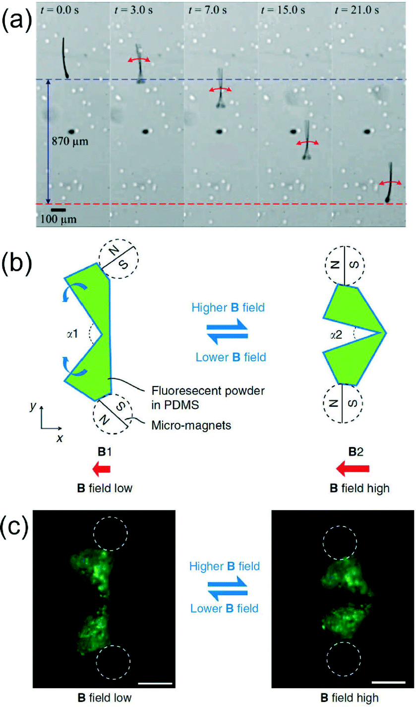 | ||
| Fig. 1 (a) MagnetoSperm moving under the influence of the oscillating (25 Hz) weak magnetic fields (~5 mT). At t = 0 s, zero magnetic field is applied. At t = 1 s, oscillating weak magnetic fields are applied. The dashed blue and red lines indicate the starting and ending positions of the MagnetoSperm. Reprinted from ref. 1 with permission from AIP Publishing LLC. (b) Schematic drawing of the micro-scallop from top view. The green shapes illustrate the opening and closing shape change of the micro-scallop when actuated by an external magnetic field. (c) Top view (microscope image) of the micro-scallop under ultraviolet illumination. The positions of the micromagnets are illustrated by white dashed circles. Scale bar is 200 μm. Reprinted from ref. 2 with permission from Nature Publishing Group. | ||
To investigate a more complex, magnetically activated microswimmer, Qiu et al.2 used a Connex Object260 3D printer to design a high-temperature polymer mold to cast a polydimethylsiloxane (PDMS) scallop capable of an open and close mechanism for propulsion. The scallop, composed of two PDMS shells (300 μm thick) linked by a PDMS hinge (60 μm thick, 200 μm long), was modified with two neodymium magnets attached to each shell. When exposed to an external magnetic field, the two magnets align with the field, closing the scallop. When the magnetic field is decreased, the restoring force of the PDMS hinge allows the scallop to open again.
The opening angle (α) between the two PDMS shells was related to the strength of the applied magnetic field (B) as shown in Fig. 1b and c. The micro-scallop was immersed in shear thickening (fumed silica suspensions) and shear thinning (hyaluronic acid) non-Newtonian fluids and motility was tested with asymmetric and symmetric actuation using the magnetic field. No net displacement of the scallop was observed in either fluid with symmetric actuation, but with asymmetric actuation the scallop achieved an average velocity of 5.2 μm s−1 (3.5% body length cycle−1) and 3.8 μm s−1 (2.5% body length cycle−1) in shear thickening and shear thinning fluid respectively. There have been few investigations of microswimmers in non-Newtonian fluids even though the fluids are commonly found in living organisms including saliva, blood, and mucus. The MagnetoSperm and scallop microrobot demonstrate swimming capabilities that may prove useful in the future design of microswimmers for in vivo applications.
To mimic the revolving helices observed in motile bacteria, a rotating, magnetic swimmer was designed by Tottori et al.3 for controlled cargo transport. The helical design of the swimmer was constructed using two-photon lithography by selectively polymerizing SU-8 or IP-L photoresist on a surface. The non-polymerized photoresist was removed with developer leaving the structure of the 3D helical microrobot swimmer on the surface as shown in Fig. 2a–c. For magnetic control, a 100 or 50 nm nickel layer was deposited with electron beam evaporation followed by a 5.0 nm coating of titanium for increased biocompatibility. To investigate the swimmer's possible cytotoxic effects, arrays of helices attached to a surface were cultured with C2C12 mouse myoblasts. Cells remained attached and continued to proliferate after 72 hours of incubation ensuring the swimmer was compatible with biological tissue. The motility of the helices was tested with multiple swimmer lengths and diameters. The smallest helical structure produced had a length of 8.8 μm and a diameter of 2.0 μm. In a rotating magnetic field, the helical swimmers demonstrated a corkscrew like swimming motion and increased velocity with increased input frequency. The greatest observed velocity, 320 μm s−1 (9.1 body lengths s−1), occurred with a helical structure 35 μm long, 8.0 μm diameter, and with a helix angle of 65° in a rotating magnetic field at 60 Hz. For cargo delivery, in addition to the helical structure, a microholder consisting of six finger-like protrusions was added to one end of an ~50 μm long swimmer as shown in Fig. 2d. In de-ionized water, the helical microholder was capable of approaching a 6 μm diameter polystyrene particle, capturing the particle within the holder, transporting the particle to a desired location, and then releasing the particle back into solution. The biocompatibility, high velocity and precise control of the helical swimmer make it a promising candidate as a micromanipulator for biological applications.
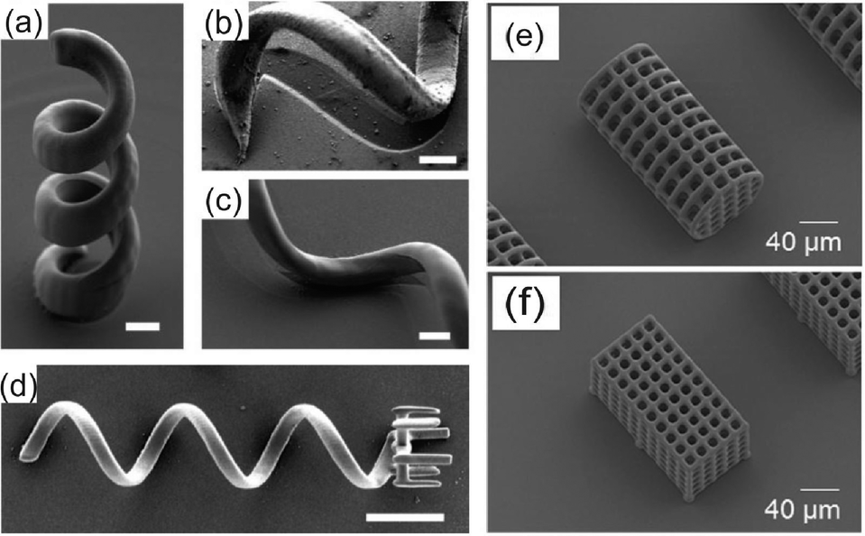 | ||
| Fig. 2 (a) The vertical helical micromachine from SU-8. (b) Shadowing effects of evaporation at a tilt angle of 0 and (c) 15°. Scale bar is 2 μm for a–c. (d) The helical micromachine with a microholder. Scale bar is 10 μm. (e) SEM image of cylindrical-shaped and (f) hexahedral-shaped microrobot. Reprinted from ref. 3 and 4 with permission from John Wiley and Sons. | ||
Using the same two-photon 3D printing method, Kim et al.4 developed an alternative cargo delivery system by designing 3D microrobot hexahedral and cylindrical cages for cell transport as shown in Fig. 2e and f. Building off the biocompatible design of the helical swimmer, Kim et al. fabricated SU-8 microcages ranging from 154 to 160 μm in length, 73 to 81 μm in diameter, with 10 to 21 μm pore sizes. The SU-8 cages were coated in 150 nm of nickel and 20 nm of titanium. After detachment from the surface the microcages were aligned vertically with the z-axis by applying an external magnetic field along the same axis. When an 800 mT m−1 external field gradient was applied in the x-direction, the maximum translational velocity of the hexahedral and cylindrical cage was 33 μm s−1 and 50 μm s−1 respectively. The lower velocity of the hexahedral microcage was attributed to its larger surface area, increasing the resistive forces during manipulation. To demonstrate the feasibility of the microcages as cell transporters, human embryonic kidney (HEK) 293 cells were cultured on the cages after they were coated with a thin layer of poly-L-lysine. After four days of culture, the HEK 293 cells had integrated the pores of the 3D structures indicating the cages could be embedded in in vivo environments. The reports from both Tottori et al. and Kim et al. establish that 3D printing using two-photon lithography is a powerful tool for fabrication of original microscale swimmers and transport mechanisms that have future biomedical robotic applications.
Cell powered motility of 3D bio-hybrid systems
Engineered 3D materials merged with biological systems, known as bio-hybrids, are an exciting step forward for the development of robotics for in vivo applications. Integration of contractile muscle cells with synthetic polymers has led to the development of multiple biologically powered motors and bio-hybrid systems capable of motility. Biologically driven motors offer the opportunity to efficiently convert chemical energy into mechanical work for the propulsion of 3D printed devices. Unlike the non-biologically friendly fuel sources used for catalytic motors,5 such as hydrogen peroxide, bio-hybrid systems are fueled by the surrounding biological fluid. Skeletal or cardiac muscle cells integrated onto biocompatible polymers contract, producing bending or deformation of the polymer to initiate motion. Cardiomyocytes will spontaneously contract and generate a 1–14 μN force while skeletal C2C12 myoblasts have been shown to generate a 15–20 μN force with electrical stimulation. Recent research with these cell types and their integration onto 3D printed materials for bio-hybrid motility is discussed here.For the formation of an untethered, crawling bio-hybrid, Cvetkovic et al.6 fabricated a 5 mm long hydrogel poly(ethylene glycol) diacrylate dual pillar-beam design using a stereolithography apparatus (SLA) for 3D printing as shown in Fig. 3a. The printed scaffold was coated in a gelatin mixture of extracellular matrix (ECM) proteins and C2C12 skeletal muscle myoblasts. After a week of culture, the C2C12 cells formed a dense muscle strip spanning the two pillars (Fig. 3b). Formation of the muscle strip produced an inward force, pulling on the two beams. Thus, the mechanical stiffness of the hydrogel was optimized by varying the energy used for polymerization within the SLA for maximum locomotion of the bio-hybrid crawler. Electrical stimulation of the C2C12 cell strip was provided with a bipolar electrical pulse train to give a consistent maximum cell contraction rate at 4 contractions s−1 at 4 Hz. A symmetric design of the hydrogel structure yielded little or no motion with the electrically stimulated muscle strip, so an asymmetrical pillar system was designed to increase net displacement by extending the height of a single pillar. The asymmetric hydrogel–cell system resulted in a maximum crawling velocity of 117.8 μm s−1 with motion in the direction of the larger pillar as shown in Fig. 3c. A similar dual pillar design integrated with C2C12 cells was developed by Sakar et al.7 for creation of a bioactuator. Instead of a hydrogel, the 3D scaffolding was fabricated with PDMS using standard lithography techniques allowing the dimensions of the system to be in the 500 μm to 1000 μm range, with the pillars anchored to the substrate. The PDMS was coated in Matrigel™ to encourage C2C12 tissue formation across the pillars. Unlike the previous system, the cell powered actuator was not contracted by external electrical stimuli, but by optogenetic control. Here, the C2C12 cells were transfected with the light activated cation channel, Channelrhodopsin-2 (ChR2) before attachment to the polymer pillars. Upon exposure to pulsed blue light, the C2C12-ChR2 cell membranes depolarized and induced cell contractions. Spatial control over cell contraction was regulated by changing the diameter of the light stimuli to contract an individual cell or cell clusters within the tissue. C2C12 cells spanning the two PDMS pillars, exposed to blue light contracted, pulling the flexible pillars inward creating a bio-hybrid actuator. Illuminating one side of the cell–pillar structure would only allow contraction of C2C12 cells on that side, causing a torsional rotation of the caps of the pillars, allowing coordinated contraction (Fig. 3d) that is not observed with electrical stimuli. Both C2C12–pillar systems from Cvetkovic et al. and Sakar et al. demonstrated robotic actuation using an external stimulus useful for investigating biomechanics and developing biologically compatible soft robots.
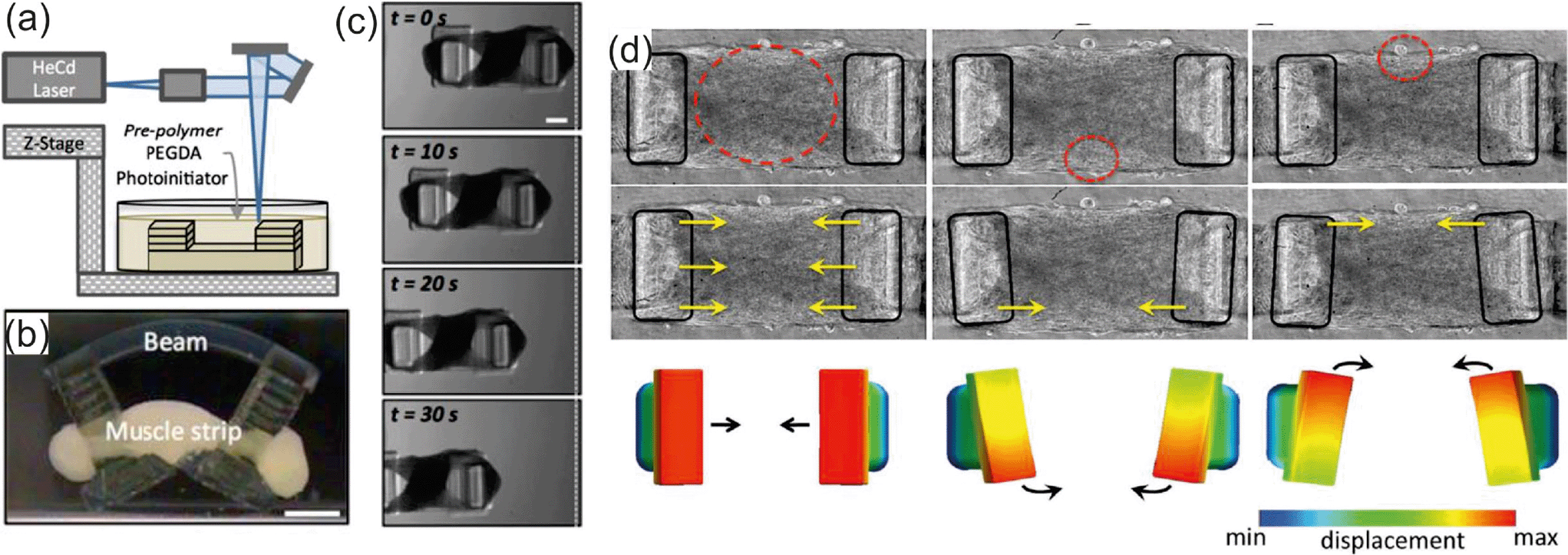 | ||
| Fig. 3 (a) An SLA was used to polymerize hydrogel structures in an additive process. (b) Cells and matrix compacted around the pillars of the bio-bot to form a solid muscle strip. (c) Top-view time-lapse images of the asymmetric bio-bot movement. Scale bars are 1 mm. Reprinted from ref. 6 with permission from the National Academy of Sciences. (d) Multi degree of freedom actuation of a C2C12-ChR2 muscle strip with local stimulation. Heat maps depict the degree of displacement. Reprinted from ref. 7 with permission from the Royal Society of Chemistry. | ||
Other than actuation, contractile cells have also been employed for powering artificial robotic swimmers. In an alternative design to the magnetic artificial sperm or helical swimmers mentioned previously, Williams et al.8 designed a PDMS sperm propelled by the contractile motion of primary cardiomyocytes. For optimal motility, dimensions of the sperm were determined by computational modeling of an elastohydrodynamic system with a free filament driven by a periodic actuator.
Using these parameters, a mold for the PDMS sperm was created using inductively coupled plasma deep reactive ion etching on a silicon wafer for a 22 μm deep pattern. The pattern was filled with uncured PDMS using capillary draw for formation of the 2 mm long body with a 57 μm wide head and 7 μm wide tail. To selectively functionalize the cured PDMS spermatozoa, a bovine gelatin mask was applied to the tail followed by incubation in Pluronic F-127 to restrict cell adhesion. The head and neck of the sperm was coated in fibronectin to encourage cardiomyocyte attachment. The modified PDMS sperm was cultured with primary cardiomyocytes extracted from 2–4 day old Sprague-Dawley rats for 24 to 48 hours before monitoring the bio-hybrid robot swimmer. Contractions of cells on the PDMS sperm neck generated angular deflections of 30–45° and a bending wave that propagated down the tail to thrust the swimmer forward. Cardiomyocyte attachment was restricted to the head and neck of the sperm to prevent cell contraction on the sperm tail. Uniform cell culture on the sperm body would yield simultaneous bending and relaxation of the tail and result in zero net motion of the swimmer. The final sperm–cell bio-hybrid reached an observed speed of 9.7 μm s−1 (0.5% body lengths s−1) with a cell contraction at approximately 3 Hz. The single-tailed sperm swimmer was compared to a two-tailed swimmer without a fabricated head. Here, the cardiomyocytes were attached to the middle of a PDMS filament where synchronized contraction of the cells was propagated to both sides of the filament to increase the swimming velocity to 81 μm s−1 (8.3% body lengths s−1) compared to the single-tailed sperm. These biologically powered sperm demonstrated that robotic swimmers do not need external stimulation and swimmer propulsion mechanisms can be generated by cell contraction.
These publications highlight the importance of small-scale robotic design for biomedical applications. 3D printing techniques allow for the fabrication of complex synthetic materials that can improve robotic motility in in vitro and in vivo systems. Understanding and mimicking the locomotive mechanisms of natural swimming organisms has been essential for the design of artificial 3D microswimmers that could be used for drug delivery or cargo transport. Integrating contractile cells onto 3D printed materials for bio-hybrids represents the next step for incorporating robotics in living tissue. Here, cells are providing mechanical energy for motion or propulsion making the devices biocompatible while still allowing them to function in confined spaces. Ultimately, these 3D printed machines are at the forefront of merging materials science and biology for motile robotics which will be a new field in future medical technologies.
Acknowledgements
The authors thank the European Research Council (ERC) for Starting Grant “Lab-in-a-tube and Nanorobotics biosensors; LT-NRBS” [no. 311529] for financial support.References
- I. S. M. Khalil, H. C. Dijkslag, L. Abelmann and S. Misra, Appl. Phys. Lett., 2014, 104, 223701 Search PubMed.
- T. Qiu, T.-C. Lee, A. G. Mark, K. I. Morozov, R. Munster, O. Mierka, S. Turek, A. M. Leshansky and P. Fischer, Nat. Commun., 2014, 5, 5119–5119 CrossRef PubMed.
- S. Tottori, L. Zhang, F. Qiu, K. K. Krawczyk, A. Franco-Obregon and B. J. Nelson, Adv. Mater., 2012, 24, 811–816 CrossRef CAS PubMed.
- S. Kim, F. Qiu, S. Kim, A. Ghanbari, C. Moon, L. Zhang, B. J. Nelson and H. Choi, Adv. Mater., 2013, 25, 5863–5868 CrossRef CAS PubMed.
- S. Sánchez, L. Soler and J. Katuri, Angew. Chem., Int. Ed., 2015, 54, 1414–1444 CrossRef PubMed.
- C. Cvetkovic, R. Raman, V. Chan, B. J. Williams, M. Tolish, P. Bajaj, M. S. Sakar, H. H. Asada, M. T. A. Saif and R. Bashir, Proc. Natl. Acad. Sci. U. S. A., 2014, 111, 10125–10130 CrossRef CAS PubMed.
- M. S. Sakar, D. Neal, T. Boudou, M. A. Borochin, Y. Li, R. Weiss, R. D. Kamm, C. S. Chen and H. H. Asada, Lab Chip, 2012, 12, 4976–4985 RSC.
- B. J. Williams, S. V. Anand, J. Rajagopalan and M. T. A. Saif, Nat. Commun., 2014, 5, 3081 Search PubMed.
| This journal is © The Royal Society of Chemistry 2015 |