 Open Access Article
Pneumatically-actuated artificial cilia array for biomimetic fluid propulsion†
Benjamin
Gorissen
a,
Michaël
de Volder
*ab and
Dominiek
Reynaerts
a
aDepartment of Mechanical Engineering, Katholieke Universiteit Leuven, Celestijnenlaan 300B, 3001 Leuven, Belgium. E-mail: michael.devolder@mech.kulueven.be
bInstitute for Manufacturing, Dept. of Engineering, University of Cambridge, 17 Charles Babbage Road, Cambridge, CB3 0FS, UK
First published on 23rd September 2015
Abstract
Arrays of beating cilia emerged in nature as one of the most efficient propulsion mechanisms at a small scale, and are omnipresent in microorganisms. Previous attempts at mimicking these systems have foundered against the complexity of fabricating small-scale cilia exhibiting complex beating motions. In this paper, we propose for the first time arrays of pneumatically-actuated artificial cilia that are able to address some of these issues. These artificial cilia arrays consist of six highly flexible silicone rubber actuators with a diameter of 1 mm and a length of 8 mm that can be actuated independently from each other. In an experimental setup, the effects of the driving frequency, phase difference and duty cycle on the net flow in a closed-loop channel have been studied. Net fluid speeds of up to 19 mm s−1 have been measured. Further, it is possible to invert the flow direction by simply changing the driving frequency or by changing the duty cycle of the driving block pulse pressure wave without changing the bending direction of the cilia. Using PIV measurements, we corroborate for the first time existing mathematical models of cilia arrays to measurements on prototypes.
1. Introduction
Biomimicry has been a long standing fascination of mankind.1 Nature's selection principles have often evolved very elegant solutions to complex problems and have been a continuous source of inspiration for engineering design.2 Biologic processes taking place at the microscale are often fascinating, yet these are difficult to mimic because of fabrication challenges. However, with the advent of micro and nanotechnology, we now have a new set of tools to better imitate biologic microorganisms. In particular, this paper reports a new cilia-driven propulsion mechanism. Cilia are beating, thin hair-like structures found, for instance, on the surface of small organisms to propel them in liquids. Examples include bacteria,3 eukaryotes,4 and algae,5 but parts of the human body such as the lungs are also lined with arrays of cilia that are working in unison to produce a wave-like movement to sweep mucus.6 Cilia in nature often operate in laminar regimes where fluid propulsion is only possible if an asymmetrical motion is created. This was pointed out by Purcell and is better known as the scallop theorem:7 scallops are able to propel themselves by opening their shell slowly and closing it rapidly. However, in a laminar flow regime, this would yield no net propulsion since flow inertia is irrelevant at low Reynolds numbers (Re). The same is true for cilia which can only operate in laminar regimes if asymmetry is introduced in the operation. Besides cilia operating at low Re, organisms in nature also use ciliary locomotion at much higher Re. An example of this can be found on the tentacles of ctenophores5 which are lined with cilia that induce fluid flow with Re between 50 and 200.In nature, four types of ciliary asymmetry are found to achieve efficient propulsion. Three of them act on the level of a single cilium:6 spatial asymmetry, where effective and recovery strokes do not follow the same path; orientational asymmetry, where the mean axis of the cilium is spatially tilted away from the surface normal; and temporal asymmetry where effective and recovery strokes have different velocities. At the level of the cilia array as a whole, additional asymmetry can be created by generating metachronal waves where a phase difference in actuation is present between neighboring cilia.8 Cilia in nature usually combine different types of asymmetry to form complex beating patterns.4
Over the past few years, there has been a considerable effort in simulating and fabricating artificial cilia arrays to better understand the locomotion of biological organisms. From a theoretical perspective, numerical studies by Alexeev et al.,9,10 Khaderi et al.,6,11–14 and Vilfan et al.15 showed the effect of the different types of asymmetry on fluid flow. These studies showed that for low Re, spatial asymmetry is absolutely essential for a fluid flow to occur. This fluid flow can be enhanced by introducing orientational asymmetry and metachronal asymmetry. Metachronal asymmetry has a big influence at low Re: even a small phase difference can increase the net fluid flow substantially, with an absolute maximum in fluid flow when the direction of wave propagation is opposite to the stroke of an individual cilium (antiplectic metachrony). As indicated by the scallop theorem, temporal asymmetry has no effect at low Re. For high Re, any type of asymmetry will propel fluid. And even if no asymmetry is present, fluid propulsion normal to the ciliary surface is observed.16 Although actuation at high Re generates higher flow rates than at low Re, similar conclusions could be made in terms of orientational and spatial asymmetry: changing the orientation has an influence on the flow direction and a higher flow rate can be seen at larger spatial asymmetry.
These theoretical investigations have been complemented by experimental studies using electrostatic cilia,17 magnetic cilia,8,18–23 optically-driven cilia,24 electroactive polymer-driven cilia,25 resonance-driven cilia16 or mechanically-driven cilia,26–28 all focusing on the effect of spatial asymmetry and orientational asymmetry. The effect of metachrony with a fixed phase difference between cilia has been experimentally studied by Hussong et al.8 by using a rotational magnetic field. However, the effect of changing phase difference in metachronal waves on the net fluid flow has largely been omitted in the experimental work, mainly because of the difficulties in the changing phase difference between cilia when using the actuation mechanisms described above.
In this paper, we propose a new type of artificial cilia that are driven by flexible pneumatic microactuators.29–31 These actuators, like biologic cilia, can generate large sweeping motions at high bandwidths.32,33 Further, they are fabricated using a single step micromoulding process which allows straightforward fabrication of cilia arrays. Our technology is interesting from a theoretical point of view, because each cilium can be controlled independently, which allows, for the first time to truly study the effect of phase difference on fluid flow. This experimental work corroborates numerical studies performed previously by other groups including that of Khaderi et al.12 who, at low Re, theoretically simulated a system very similar to our experimental test setup.
From an application point of view, we envision the cilia array to be attractive for pumping fluids in microfluidic systems, as well as to mix fluids and propel miniature robots. The latter can find applications in both medical and industrial inspection operations. We believe our cilia are particularly suitable in these domains because pneumatic actuators show advantageous force outputs at the microscale,34 and because our cilia are made out of a soft biocompatible material (polydimethylsiloxane – PDMS), they are unlikely to damage their surroundings.35
2. Experimental
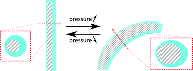
This research for the first time proposes to fabricate cilia based on flexible bending actuators. These actuators were first introduced by Suzumori et al.36 and Konishi et al.,37 and are mainly used in surgical tools,38 robotic grippers,36 large swimming robotic fishes39 and walking robots.40 Essentially, these pneumatic bending actuators consist of a closed hollow tube made out of a highly flexible material that can be pressurized. If the tube cavity (hatched area in the cross sections of Fig. 1) is concentric, as in the case of regular tubes, the tube would simply expand in diameter when pressure is applied. However, as is shown in Fig. 1, an eccentric void causes the actuator to bend when pressurized.The biomimicking actuators used in this paper are hollow eccentric cylinders made out of PDMS, which are produced by a high aspect ratio moulding process,31,33,41 as shown in detail in Fig. 2. The cavity of the actuator is formed by a polished tungsten carbide microrod with a diameter of 0.61 mm placed in one half of the mould. The other half of the mould consists of a microdrilled hole that defines the outer dimensions of the actuator (diameter of 1 mm and length of 8 mm). Alignment of both halves of the mould is achieved using locating pins which are positioned accurately to define the eccentricity (0.14 mm) between the microrod and the drilled hole. After closing the mould, liquid PDMS (Sylgard 184 – ratio 1![[thin space (1/6-em)]](https://www.rsc.org/images/entities/char_2009.gif) :
:![[thin space (1/6-em)]](https://www.rsc.org/images/entities/char_2009.gif) 10) is poured in and cured at 90 °C for 15 minutes. Demoulding of the actuator finishes the production process, which is described in more detail in a previous publication.33 Pressurizing the eccentric void at a pressure of 0.2 MPa results in a large bending deformation, similar to the motion of a single natural cilium, as can be seen on the embedded pictures in Fig. 3. With a failure pressure of 0.25 MPa to 0.28 MPa,33 the actuation pressures in this research are well within safety limits. During the course of this research, despite over 500
10) is poured in and cured at 90 °C for 15 minutes. Demoulding of the actuator finishes the production process, which is described in more detail in a previous publication.33 Pressurizing the eccentric void at a pressure of 0.2 MPa results in a large bending deformation, similar to the motion of a single natural cilium, as can be seen on the embedded pictures in Fig. 3. With a failure pressure of 0.25 MPa to 0.28 MPa,33 the actuation pressures in this research are well within safety limits. During the course of this research, despite over 500![[thin space (1/6-em)]](https://www.rsc.org/images/entities/char_2009.gif) 000 actuation cycles for each actuator, no signs of wear or other failure were observed.
000 actuation cycles for each actuator, no signs of wear or other failure were observed.
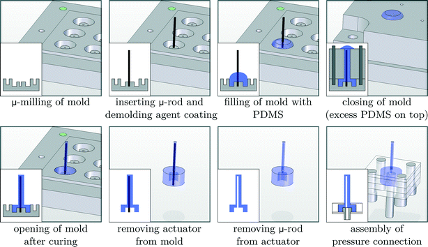 | ||
| Fig. 2 Overview of the production process, with cross-sectional views shown on the inset images in the lower left corner, to fabricate biomimicking pneumatic actuators. | ||
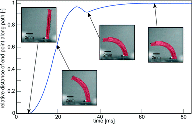 | ||
| Fig. 3 Impulse response of a pneumatic cilium in water with an outer diameter of 1 mm, length of 8 mm, inner diameter of 0.61 mm and eccentricity of 0.14 mm on a pressure step of 0.2 MPa. Embedded pictures show its actual bending deformation. Movie S1 (ESI†) shows a recording of this experiment. | ||
Single cilium test setup
To calculate Reynolds number based on the tip speed of the cilium, a single cilium was placed in a transparent PMMA container filled with water and loaded with a pressure step of 0.2 MPa. High-speed camera pictures were taken at a frame rate of 1500 Hz using a CMOS camera (HighSpeedStar 5 – LaVision) to track the actuator tip position. Movie S1 (ESI†) shows a recording of this experiment.The tip of the cilium follows the same path when being pressurized and when being depressurized, thus having no spatial asymmetry. Because the bending motion is solely towards one side, a single cilium exhibits orientational asymmetry and should induce fluid flow at Re ≥ 1.6 To study the effect of only orientational asymmetry on the fluid flow, a fast switching (<2 ms switching time) solenoid valve (MHE2- Festo) was used to periodically excite a single cilium submerged in water with a block pressure waveform of 0.2 MPa. The fluid flow is visualized by using ink droplets and the images are captured using the same high-speed camera.
Cilia array test setup – net fluid flow
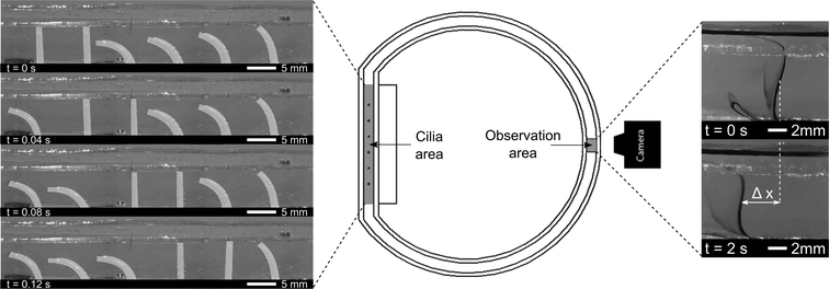
Six pneumatic bending actuators were positioned in line with a spacing of 8 mm to form a ciliated surface. These cilia were put in a transparent PMMA closed-loop flow channel, as shown in Fig. 4. Closed-loop flow channels make the net flow easier to quantify with respect to an open-loop setup, where the equilibrium state is characterized by a pressure difference created by the cilia instead of the net flow. This pressure difference would force backflow within the cilia area, which is minimized by using a closed-loop flow setup.22Six fast switching solenoid valves (MHE2- Festo) are controlled individually, allowing for imposing pressure waves with arbitrary phase shifts. The frequency, phase difference and duty cycle are converted by a controller (CompactRio with FPGA module, programmed by Labview) to six digital output signals (0–24 V), one for each valve. The digital signals are block waves that are converted by the 3/2-way valves to a pressure block wave, with a switching time of less than 2 ms. The actuators are consequently connected to a pressure vessel at a 0.2 MPa gauge pressure when the valve is actuated or to atmospheric pressure when not actuated. To minimize loss in bandwidth, tubing is made as short as possible.
The effective stroke of the cilia is defined as the movement from an upright to a bent state when being pressurized. Positive fluid flow is defined as being in the same direction as the effective stroke, and metachronism of the waves is defined as follows:12 symplectic metachrony where the wave travelling and effective stroke directions are the same, and antiplectic metachrony where the wave travelling and stroke directions are opposite. The duration of the bent state vs. the upright state can be continuously changed by altering the duty cycle of the pneumatic valves. As an example, an antiplectic metachronal wave with a duty cycle of 80% (80% of a period the actuator is bent) and a phase difference of 45° can be seen in Fig. 4 (left). Lastly, the actuation frequency which is independent of duty cycle and phase difference, can also be changed.
A line of ink is used to visualize the net flow on the opposite side of the circular channel, indicated as the ‘observation area’ in Fig. 4 (middle). At this location, laminar flow conditions are observed, and at small time intervals, no diffuse mixing of ink was seen, as is shown by Movie S2 (ESI†). The induced flow varies across the height of the fluidic channel, being zero at the bottom channel wall, and reaching a constant speed from 2 mm to 8 mm above the bottom wall. Maximum flow speeds are observed at the interface between water and air. As will be shown in the PIV results section, this max flow region in the observation area coincides with the region of max flow generation in the cilia area: just above the tips of the cilia. These results corroborate the research of Chen et al.23 where maximum flow speeds are observed in the region of the cilia tips. To characterize the induced net flow speed, all fluid flow speed measurements were taken in the constant speed region at a height of 6 mm above the flow channel bottom. Two consecutive still images of the ink lines were used to determine the advancement of the line of ink, as shown by Δx in Fig. 4 (right). Given the time (Δt) between consecutive images, net flow speeds ‘V’ can be calculated (V = Δx/Δt). To reduce measurement errors, the flow speeds for a specific combination of parameters were averaged out over four measurements.
Cilia array test setup – PIV
Particle image velocimetry (PIV) is used to visualize fluid flow around the six cilia, to see how net propulsion is generated. Using 2D PIV, velocities in the third dimension are not being captured. Previous research8,19,20,26 captured velocities through PIV in a plane perpendicular to the upright cilia, while in this study, the visualization plane coincide with de actuation plane. Numerically, Khaderi et al. showed that velocity profiles in this plane are essential in explaining metachronic fluid propulsion.12Fluorescent tracer particles were used to interact with planar laser light (Dual Cavity Nd:YLF Pegasus-PIV laser from NewWave) that is aligned with the actuation plane of the cilia. Because of diffractive problems, a new closed-loop test setup has been constructed with flat transparent side walls for laser light illumination and high-speed camera recordings. A uniform channel cross section of 10 mm × 3 mm has been made by micromilling of aluminum that was painted black to reduce backscatter. The transparent sidewalls were made out of 3 mm thick sheets of PMMA by means of laser cutting. The top and frontal views of this setup can be seen in Fig. 5a and b. High-speed camera pictures were taken at a frame rate of 250 Hz using a CMOS camera (HighSpeedStar 5 – LaVision) as shown in Fig. 5c and on Movie S3 (ESI†). To compensate for distortion due to the light diffraction of PMMA and water, the acquisition system is calibrated using a 2D calibration plate comprising a precision grid of 1 mm diameter holes with a spacing of 2 mm, made by micromachining. Successive camera images are correlated using the DaVis 7.1 software of LaVision GmbH to calculate velocity vectors, Fig. 5d. To reduce noise, the velocity vectors were averaged by combining results from 40 synchronized actuation periods.
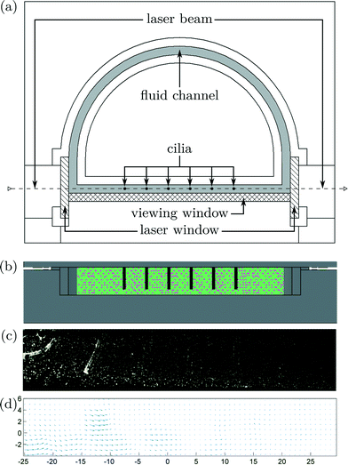 | ||
| Fig. 5 a) Top view of the PIV test setup with a closed-loop fluid channel in grey; hatched surfaces indicate transparent PMMA dividers through which planar laser light (dashed line) can shine. High-speed camera images are taken through another PMMA divider (cross-hatched surface) to visualize the fluid motion. Cilia are depicted by black circles and by black rods in b), the frontal view. c) Image acquired by the high-speed camera at a sampling frequency of 250 Hz, as can be seen in Movie S3 (ESI†). d) Calculated fluid speeds by correlating successive high-speed camera images. | ||
3. Results
Single cilium test setup
To determine Reynolds number, a pressure step of 0.2 MPa is imposed on a single cilium, as illustrated in Fig. 3 and Movie S1 (ESI†). This figure shows the response of the actuator to a pressure step that is characterized by the relative position of the tip of the actuator along its actuation path, with a value of ‘1’, indicating a full stroke. This response shows a time constant (τ) of 0.014 s, which is the time the actuator takes to complete 63% of its full stroke, resulting in a bandwidth in water of 11 Hz (BW = 1/(2πτ)). In this 0–0.014 s time interval, there is an approximately linear relation between time and displacement, meaning that the cilium tip exhibits a nearly constant speed. This was calculated to be 0.435 m s−1. Combining this with the length L of an actuator (8 mm) and kinematic viscosity of water (1.10−6 m2 s−1) yields a Reynolds number (Re = VL/ν) based on the tip speed of the cilium of 3480. This means that inertial effects play an important role in the fluid flow caused by a single cilium and a cilia array in this paper.To show the effect of purely orientation asymmetry on fluid flow at high Re, a single cilium was actuated with a block pulse pressure sequence with a duty cycle of 50% at various frequencies (0–35 Hz). Fig. 6 shows the high-speed camera images of the fluid (water and ink) before actuation at 10 Hz (0 cycles), and after 4, 8 and 12 cycles (Movie S4 (ESI†) shows a recording of this experiment). This sequence clearly shows the net propulsion in the direction of the effective stroke and confirms the conclusion theoretically made by Khaderi et al.:6 at high Re, purely orientation asymmetry causes a positive net propulsion that is fully unidirectional. Fig. 6 also shows the formation of air bubbles on the surface of the actuator after being submerged in water for a long time, due to the permeation of PDMS. To reduce this effect, measurements were done immediately after filling the channel with water, for the remainder of this research. In applications with prolonged submersion, coating the actuators with a non-permeant, flexible material is needed to avoid air bubble formation.
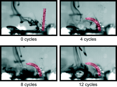 | ||
| Fig. 6 Captured images of single-cilium water propulsion at an actuation frequency of 10 Hz and duty cycle of 50%. Movie S4 (ESI†) shows a recording of this experiment. | ||
Cilia array test setup – net fluid flow
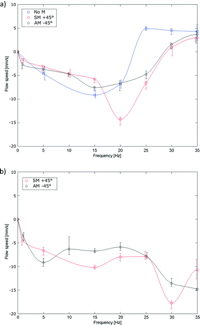
Ciliary propulsion with synchronal beating patterns have been studied in depth both theoretically6,9 and experimentally21,22 for both high and low Re. On the other hand, metachronal beating patterns were only studied at low Re.8,12 To study high Re behavior, metachronal asymmetry was changed by setting the phase difference between cilia to +45° (symplectic metachrony), 0° (no metachrony) or −45° (antiplectic metachrony). In Fig. 7a, metachrony is changed for a duty cycle of 80% and in Fig. 7b for a duty cycle of 20%. For actuation frequencies up to 11 Hz, the effect of only changing metachrony can be seen; at higher frequencies, orientational asymmetry must also be taken into account as will be discussed later. At these low frequencies, a net flow opposing the bending direction of an individual cilium was observed where no clear conclusions could be made in terms of which type of metachrony is best for generating fluid flow. This is different from low Re fluid flow, where theoretically it was shown12 that introducing even a little phase difference between cilia increases the fluid flow substantially, with an absolute maximum for antiplectic metachrony.At high frequencies, orientational asymmetry was changed indirectly by setting the duty cycle to 80% or 20%; at frequencies above the bandwidth of the actuator (11 Hz), it was observed that the actuator isn't able to follow the imposed pressure profile and shows a reduced stroke around a mean bending direction, as can be seen in Fig. 8 and Movie S5 (ESI†). The cilia actuator acts as a low pass filter to the imposed block wave pressure profile, with a DC signal that is proportional to the duty cycle, according to Fourier series analysis. This DC signal is accounted for the mean bending direction that can be characterized by an orientation angle θ which is a measurement of orientational asymmetry. Thus, above the bandwidth of the actuator, this orientation angle varies monotonically with the duty cycle, with its extremities being upright at a duty cycle of 0% and fully flexed at a duty cycle of 100%.
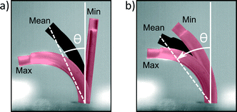 | ||
| Fig. 8 Reduction in stroke when the actuation frequency changes from 1 Hz a) to 35 Hz b) for a duty cycle of 50%. Each picture is a superposition of three high-speed camera still images, indicating the lower limit of the stroke (Min), upper limit of the stroke (Max) and the mean value (Mean). The angle between the normal of surface on which the cilia are implanted and the mean bending direction is indicated by θ, the orientation angle of the bending deformation. Movie S5 (ESI†) shows a recording of this experiment. | ||
When looking at frequencies well above the bandwidth of the actuator (≫11 Hz), flow reversal is observed when duty cycle and thus orientational asymmetry is changed (comparing Fig. 7a to b). This is a remarkable result because the orientation angle doesn't have to change its sign for a flow reversal to occur. A similar flow reversal phenomenon can be seen when increasing the frequency at a fixed duty cycle of 80% regardless of the type of metachrony (see also Movie S6 in the ESI†). This result corroborates the theoretical study of Alexeev et al.9 where a synchronal flow reversal was predicted at low Re due to a frequency-caused stroke reduction. The time needed for the induced flow to stop and flow in the other direction is in the order of 2 s, when changing frequency from 30 Hz to 5 Hz for the fluid propulsion with a duty cycle of 80% and a +45° phase difference.
The absence of the flow reversal at a duty cycle of 20% suggests that in a high Re flow, both stroke reduction and orientational asymmetry are needed to fully explain the flow direction, which will be discussed in the PIV measurement subsection. However, two mechanisms are introduced to change the flow direction: changing the frequency or changing the duty cycle above the bandwidth of the actuator. These mechanisms complement the method of Chen et al.,23 which states that inducing flow reversal by changing the rotational direction of magnetically actuated cilia. The presented methods are important for future small-scale lab-on-a chip applications and small swimming robots as it allows to easily reverse the propulsion direction.
Cilia array test setup – PIV
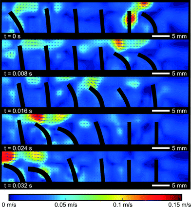
To further investigate the difference between the propulsion caused by a single cilium and cilia arrays, PIV flow analysis is used to visualize the flow in and around a cilia array. A symplectic metachronic wave with a frequency of 20 Hz, a duty cycle of 20%, and a phase difference of 45° was applied, giving a steady net flow of −8 mm s−1, opposite to the bending direction of the cilia. Contours of the cilia were captured by the high-speed camera and superimposed on the velocity fields, as shown in Fig. 9. The colors indicate the magnitude of the velocity field and direction as shown by the arrows.These pictures show how a negative net fluid flow is created in a 2D cross section of the cilia array. In the first frame, the first (rightmost) cilium commences its bending motion. The fluid that was trapped between the first and the second cilium is pushed over the first cilium towards the right, because the void that this cilium is leaving behind needs to be filled. The narrow spacing inside the channel (width 3 mm vs. actuator diameter of 1 mm) forces the fluid to go over the actuator tip. Consequently, a small volume of fluid has been transported from the left side of this actuator to the right side. If no other cilia were present (and in the perfect case of no orientational asymmetry), the reciprocal movement of the actuator would cause the fluid volume to be transferred from right to left again without causing a net fluid propulsion. However, in the next frame, when the second cilium commences its bending motion, another fluid volume will be transferred from the left side of cilium 2 to its right side. And this volume will fill in the void that the first cilium leaves behind when it becomes upright again. This will continue until the last cilium transfers its volume of fluid from left to right, sucking in a new volume of fluid from the left when it comes upright again. Globally after one cycle, one volume of fluid is transferred from the left hand side of the cilia array to the right hand side, giving rise to a net fluid flow similar to the operation of a peristaltic pump.
This PIV measurement also explains why propulsion by a single cilium (Fig. 6) is very different from cilia array propulsion. The force generated by a single cilium is directly transferred to the fluid in the direction of the effective stroke. For cilia arrays, this momentum is blocked by the second cilium that stands in its wake. This blockage forces the fluid to go over the actuated cilia in a direction opposing the effective stroke. A similar mechanism of blocking fluid in metachronic waves has been theoretically predicted by Khaderi et al.12 for low Re. This blocking mechanism is only possible when the fluid flow in the third dimension is negligible, which is the case in a densely packed surface of cilia or in the case of cilia with a large third dimension themselves, the so called plate-like cilia. For other slender-body cilia with a large intercilium space, this blocking effect will be much lower due to the escaping of fluid at the sides of the cilia. This will result in an overall reduction of the fluid flow, as was theoretically shown by Dauptain et al.5
This blocking mechanism also explains why fluid reversal was seen when increasing the frequency at a duty cycle of 80% and not at 20%. At a duty cycle of 80% and at a frequency well above the bandwidth of the actuator, the mean bending direction of all cilia will be close to fully flexed, as was discussed above. This reduces the blocking capabilities of the cilia and thus the fluid momentum can be more easily transferred in the direction of the stroke, resulting in a flow reversal above the bandwidth of the cilia. At a 20% duty cycle and above the cilia bandwidth, the mean bending direction is close to upright, meaning that the cilia still can impose their blocking behavior and consequently, the fluid momentum still will be redirected in an opposing direction. Thus, in addition to a reduction in stroke, the mean bending direction is equally important in explaining the flow reversal at high Re. At a duty cycle of 80%, the loss of blocking capabilities will prevail only at frequencies above the bandwidth of the cilia, which explains why the net flow reversal was observed with increasing frequency.
4. Conclusions
A new type of artificial cilia based on flexible pneumatic actuators was fabricated using high aspect ratio micromoulding of PDMS. These actuators show deformations reminiscent of natural cilia, with a large stroke and fast movement (bandwidth of 11Hz in water). Six of these actuators were combined to form a cilia array where all cilia can be actuated independently using fast switching pneumatic solenoid valves. This is the first system, known to the authors, where cilia can be controlled truly independently, making it possible to study the influence of both orientational and metachronal asymmetry on high Reynolds fluid propulsion, which to date has only been studied theoretically. Using a closed-loop test setup, the maximum net flow speeds recorded were of 19 mm s−1, and the flow direction can be inverted by simply changing the driving frequency or duty cycle. Using the results of a PIV measurement, we propose the interplay of stroke reduction and orientational asymmetry to be essential for this flow reversal to occur.Acknowledgements
Benjamin Gorissen is a Doctoral Fellow of the Research Foundation – Flanders (F.W.O.), Belgium. Furthermore, the authors gratefully thank Stein Naert and Maarten Vanierschot for setting up the net flow and PIV measurements.References
- T.-S. Wong, S. H. Kang, S. K. Y. Tang, E. J. Smythe, B. D. Hatton, A. Grinthal and J. Aizenberg, Nature, 2011, 477, 443–447 CrossRef CAS PubMed.
- M. French, Invention and Evolution, Cambridge University Press, 2nd edn, 1994 Search PubMed.
- P. Satir and M. A. Sleigh, Annu. Rev. Physiol., 1990, 52, 137–155 CrossRef CAS PubMed.
- C. Brennen and H. Winet, Annu. Rev. Fluid Mech., 1977, 9, 339–398 CrossRef.
- A. Dauptain, J. Favier and A. Bottaro, J. Fluids Struct., 2008, 24, 1156–1165 CrossRef PubMed.
- S. N. Khaderi, M. G. H. M. Baltussen, P. D. Anderson, J. M. J. den Toonder and P. R. Onck, Phys. Rev. E: Stat., Nonlinear, Soft Matter Phys., 2010, 82 Search PubMed.
- E. M. Purcell, Am. J. Phys., 1977, 45, 3–11 CrossRef.
- J. Hussong, N. Schorr, J. Belardi, O. Prucker, J. Ruehe and J. Westerweel, Lab Chip, 2011, 11, 2017–2022 RSC.
- A. Alexeev, J. M. Yeomans and A. C. Balazs, Langmuir, 2008, 24, 12102–12106 CrossRef CAS PubMed.
- H. Masoud and A. Alexeev, Soft Matter, 2011, 7, 8702–8708 RSC.
- S. N. Khaderi, M. Baltussen, P. D. Anderson, D. Ioan, J. M. J. den Toonder and P. R. Onck, Phys. Rev. E: Stat., Nonlinear, Soft Matter Phys., 2009, 79, 4 CrossRef.
- S. N. Khaderi, C. B. Craus, J. Hussong, N. Schorr, J. Belardi, J. Westerweel, O. Prucker, J. Ruehe, J. M. J. den Toonder and P. R. Onck, Lab Chip, 2011, 11, 2002–2010 RSC.
- S. N. Khaderi, J. M. J. den Toonder and P. R. Onck, J. Fluid Mech., 2011, 688, 44–65 CrossRef.
- S. N. Khaderi, J. M. J. den Toonder and P. R. Onck, Langmuir, 2012, 28, 7921–7937 CrossRef CAS PubMed.
- M. Vilfan, G. Kokot, A. Vilfan, N. Osterman, B. Kavcic, I. Poberaj and D. Babic, Beilstein J. Nanotechnol., 2012, 3, 163–171 CrossRef PubMed.
- K. Oh, J.-H. Chung, S. Devasia and J. J. Riley, Lab Chip, 2009, 9, 1561–1566 RSC.
- J. den Toonder, F. Bos, D. Broer, L. Filippini, M. Gillies, J. de Goede, T. Mol, M. Reijme, W. Talen, H. Wilderbeek, V. Khatavkar and P. Anderson, Lab Chip, 2008, 8, 533–541 RSC.
- B. A. Evans, A. R. Shields, R. L. Carroll, S. Washburn, M. R. Falvo and R. Superfine, Nano Lett., 2007, 7, 1428–1434 CrossRef CAS PubMed.
- F. Fahrni, M. W. J. Prins and L. J. van Ijzendoorn, Lab Chip, 2009, 9, 3413–3421 RSC.
- A. R. Shields, B. L. Fiser, B. A. Evans, M. R. Falvo, S. Washburn and R. Superfine, Proc. Natl. Acad. Sci. U. S. A., 2010, 107, 15670–15675 CrossRef CAS PubMed.
- M. Vilfan, A. Potocnik, B. Kavcic, N. Osterman, I. Poberaj, A. Vilfan and D. Babic, Proc. Natl. Acad. Sci. U. S. A., 2010, 107, 1844–1847 CrossRef CAS PubMed.
- Y. Wang, Y. Gao, H. M. Wyss, P. D. Anderson and J. M. J. den Toonder, Microfluid. Nanofluid., 2015, 18, 8 Search PubMed.
- C.-Y. Chen, L.-Y. Cheng, C.-C. Hsu and K. Mani, Biomicrofluidics, 2015, 9 Search PubMed.
- C. L. van Oosten, C. W. M. Bastiaansen and D. J. Broer, Nat. Mater., 2009, 8, 677–682 CrossRef CAS PubMed.
- S. Sareh, J. Rossiter, A. Conn, K. Drescher and R. E. Goldstein, J. R. Soc., Interface, 2013, 10 Search PubMed.
- A. Keissner and C. Bruecker, Soft Matter, 2012, 8, 5342–5349 RSC.
- S. Nonaka, S. Yoshiba, D. Watanabe, S. Ikeuchi, T. Goto, W. F. Marshall and H. Hamada, PLoS Biol., 2005, 3, 1467–1472 CAS.
- C. E. Miller and H. Goldfarb, Trans. Soc. Rheol., 1965, 9, 10 CrossRef.
- M. De Volder and D. Reynaerts, J. Micromech. Microeng., 2010, 20 Search PubMed.
- O. C. Jeong, S. Kusuda and S. Konishi, All PDMS pneumatic balloon actuators for bidirectional motion of micro finger, Ieee, Miami Beach, FL, 2005 Search PubMed.
- A. Yamaguchi, K. Takemura, S. Yokota and K. Edamura, Sens. Actuators, A, 2011, 170, 139–146 CrossRef CAS PubMed.
- B. Gorissen, M. De Volder, A. De Greef and D. Reynaerts, Sens. Actuators, A, 2011, 168, 58–65 CrossRef CAS PubMed.
- B. Gorissen, W. Vincentie, F. Al-Bender, D. Reynaerts and M. De Volder, J. Micromech. Microeng., 2013, 23 Search PubMed.
- M. De Volder, J. Peirs, D. Reynaerts, J. Coosemans, R. Puers, O. Smal and B. Raucent, J. Micromech. Microeng., 2005, 15, S15–S21 CrossRef.
- S. Konishi, 2011 International Meeting for Future of Electron Devices (IMFEDK), 2011, pp. 20–21 Search PubMed.
- K. Suzumori, S. Iikura and H. Tanaka, Proceedings. 1991 IEEE International Conference on Robotics and Automation (Cat. No.91CH2969-4), 1991, vol. 1622, pp. 1622–1627 Search PubMed.
- S. Konishi, F. Kawai and P. Cusin, Sens. Actuators, A, 2001, 89, 28–35 CrossRef CAS.
- Y. Watanabe, M. Maeda, N. Yaji, R. Nakamura, H. Iseki, M. Yamato, T. Okano, S. Hori and S. Konishi, Small, soft, and safe microactuator for Retinal Pigment Epithelium transplantation, Ieee, Kobe, JAPAN, 2007 Search PubMed.
- K. Suzumori, S. Endo, T. Kanda, N. Kato and H. Suzuki, A bending pneumatic rubber actuator realizing soft-bodied manta swimming robot, Ieee, Rome, ITALY, 2007 Search PubMed.
- R. F. Shepherd, F. Ilievski, W. Choi, S. A. Morin, A. A. Stokes, A. D. Mazzeo, X. Chen, M. Wang and G. M. Whitesides, Proc. Natl. Acad. Sci. U. S. A., 2011, 108, 20400–20403 CrossRef CAS PubMed.
- D. Copic, S. J. Park, S. Tawfick, M. F. L. De Volder and A. J. Hart, Lab Chip, 2011, 11, 1831–1837 RSC.
Footnote |
| † Electronic supplementary information (ESI) available. See DOI: 10.1039/c5lc00775e |
| This journal is © The Royal Society of Chemistry 2015 |

