
 Open Access Article
 This Open Access Article is licensed under a
 Creative Commons Attribution 3.0 Unported Licence
Hydrogel-driven paper-based microfluidics†
Robert R.
Niedl
and
Carsten
Beta
*
Institute of Physics and Astronomy, University of Potsdam, Karl-Liebknecht-Str. 24-25, 14476 Potsdam, Germany. E-mail: beta@uni-potsdam.de
First published on 21st April 2015
Abstract
Paper-based microfluidics provide an inexpensive, easy to use technology for point-of-care diagnostics in developing countries. Here, we combine paper-based microfluidic devices with responsive hydrogels to add an entire new class of functions to these versatile low-cost fluidic systems. The hydrogels serve as fluid reservoirs. In response to an external stimulus, e.g. an increase in temperature, the hydrogels collapse and release fluid into the structured paper substrate. In this way, chemicals that are either stored on the paper substrate or inside the hydrogel pads can be dissolved, premixed, and brought to reaction to fulfill specific analytic tasks. We demonstrate that multi-step sequences of chemical reactions can be implemented in a paper-based system and operated without the need for external precision pumps. We exemplify this technology by integrating an antibody-based E. coli test on a small and easy to use paper device.
1. Introduction
The past decades have seen enormous advances in miniaturization of fluidic systems. Today, microfluidics has evolved into an omnipresent technology that dominates many fields of the applied sciences ranging from synthetic chemistry to biochemistry, biotechnology, and medicine.1–3 One of the outstanding milestones in this field was the development of soft lithography — a microfabrication technique that allows the rapid and inexpensive manufacturing of complex microfluidic devices based on polydimethylsiloxane (PDMS).4,5 Also some of the associated secondary hardware has been scaled down over the years. However, syringe pumps, tubing, power supplies, and bottles for storage of solutions are typically required to operate a lab-on-chip device. Even though most of these components are available in a well-equipped research environment, the need for high-end peripheral hardware severely limits the use of conventional microfluidics for applications outside of a laboratory context. In particular, point-of-care diagnostics or adverse operational conditions that are encountered in developing countries or conflict and disaster areas may severely hamper the use of classical microfluidics.6,7A first substantial step to successfully cope with these challenges was taken with the development of paper-based microfluidics.8–11 Here, the microfluidic device is fabricated from a paper substrate by structuring via photolithography, ink jet printing, or wax. Capillary forces drive fluid flow though the structured paper. Numerous simple assays have been implemented on such easy to use, low cost microfluidic paper analytic devices (μPADs).12 Several variants have been proposed to adapt μPADs to more sophisticated tasks, for example, layered three-dimensional paper-based devices that can distribute fluids from single inlet points into large arrays of detection zones.13 Also, it was shown that chemicals can be imprinted and stored on the paper scaffold.14 Even enzymes can be introduced and, in some cases, covalently linked to the cellulose fibers.15,16 Moreover hydrogels have been combined with paper-based microfluidics to achieve on-chip separation of analytes.17
Despite the numerous advantages — low cost fabrication, easy handling, and robust operation — paper-based microfluidic devices suffer from several drawbacks that severely limit their range of application. In particular, liquid that drives transport in the structured paper substrate is typically applied by the user from the outside. This limits the complexity of the fluidic protocol. For example, the supply of precise amounts of liquid, a controlled gradual liquid supply, or a sequential supply of specific amounts of liquid will be difficult to achieve by a non-trained user without specialized equipment. Furthermore, the purity of the on-chip processes is limited by the purity of the liquid that is introduced from the outside by the user. To offer a solution to such drawbacks, we extend the original concept of paper-based microfluidics by incorporating responsive hydrogels into the paper device.
Hydrogels consist of a network of polymer chains that are linked together by a crosslinker like methylenebisacrylamide in acrylamide gels.18 The ratio between the monomers and crosslinkers defines the mesh size of the polymerized network.19 Due to the hydrophilic character of the polymer chains, such networks can incorporate large amounts of aqueous solutions.20 By combining monomers with different side chains, the solubility of the polymer can be changed.21–24 In the case of a temperature sensitive hydrogel, this results in a lower or upper critical solution temperature (LCST or UCST, respectively).25–29 For temperatures below the LCST the hydrogel exists in a swollen state, with a large amount of liquid incorporated into the polymer network. Upon an increase of temperature above the LCST, the hydrogel collapses and the stored liquid is released.30–34 Various chemical components, including many biomolecules, can be stored and released from thermoresponsive hydrogels,35 a property that has stimulated numerous efforts to use hydrogels for drug delivery.16,34,36–39
In this article, we describe, how paper-based microfluidic devices can be combined with hydrogels to carry out complex fluidic protocols on a structured paper substrate. First, we will demonstrate how a thermoresponsive hydrogel can be used to drive fluid flow in the paper substrate in a precise and well-controlled fashion. The swollen hydrogel stores a defined volume of liquid on the paper substrate. Through a temperature-induced collapse of the hydrogel, a well-defined amount of liquid is released and moves into the structured paper substrate driven by capillary forces, without any external precision pumps. Only a small, hand-held heat supply is required to induce the hydrogel collapse, e.g., a battery-driven Peltier element. Sensitive chemicals or enzymes that are required for a specific reaction can be deposited in the dry sections of the paper channels and will be dissolved by the liquid from the hydrogel reservoirs. Alternatively, they may be also stored directly in solution inside the swollen hydrogel. In this way, different chemicals can be supplied in a well-controlled fashion to a reaction area, where a specific test assay may be performed. In the following, we will exemplify this approach with a simple, two-step color indicator reaction and with an antibody-based E. coli test assay.
2. Materials and methods
2.1 Reagents and materials
N-isopropylacrylamide 97% (NIPAM), barium peroxide (BPO), ethanol and sulfuric acid in A.C.S. purity was purchased from Sigma Aldrich, Seelze, Germany. Dextran 70 of high purity grade and citrit acid of pure grade was purchased from Carl Roth GmbH, Karlsruhe, Germany. Bisacrylamide at biochemical grade, acrylamide (AcAm) of biochemical grade, sodium hydroxid of pure grade, Munktell filter paper AB (Sweden) type 388 (70 mm diameter) was purchased from neolab Vertriebs GmbH, Heidelberg, Germany. TEMED, ammoniumpersulfate (APS) of molecular biology grade and 3,3',5,5'-Tetramethylbenzidine (TMB) was purchased from AppliChem, Darmstadt, Germany. HRP labeled E. coli-antibody (rabbit, K99, polyclonal) was purchased from antikoerper-online.de, Aachen, Germany. Negative photoresist (SU-8 2010) and developer DEV-600mr was purchased from micro resist technology GmbH, Berlin, Germany. Thymol blue sodium salt in A.C.S. purity was purchased from Alfa Aesar, Ward Hill, USA. Black ink no. 8022162 was purchased from Herlitz PBS AG Berlin, Germany. NUNC Adhesive tape (microtiterplate polyester foil) and Whatman micropore filter (0.2 μm) was purchased from VWR, Darmstadt, Germany. All material and chemicals were used as received.2.2 Fabrication of the microstructured paper tissue
The microstructured paper tissue was fabricated using standard photopolymerization techniques.8–10 Briefly, the Munktell filter paper pads were soaked in SU-8 2010 photoresist and dried at 95 °C in an oven for at least one hour. Afterwards, a photomask was put on top of the paper pad and illuminated at a wavelength of 365 nm for 6 s at 250 mJ cm−2. After the exposure, the pads were developed in DEV-600mr developer, washed with Isopropanol, and dried in an oven at 95 °C for one hour. Before usage, the paper pads were cleaned in a Harrick plasma oven (PDC 002, Ithaca, USA) for 10 minutes. If chemicals were stored in the paper structure, the solutions were applied with an Eppendorf micropipette and dried at room temperature.2.3 Fluid transport driven by capillary forces in a microstructured paper tissue
To determine the distance traveled by the liquid front in a paper microchannel (fluid run length), different volumes of ink colored water (1![[thin space (1/6-em)]](https://www.rsc.org/images/entities/char_2009.gif) :2) were applied by an Eppendorf micropipette to the reservoir area of a microchannel and the colored channel part was measured, see Fig. S1.† In the paper-based microfluidic devices that are combined with hydrogels, the fluid is provided by the collapsing hydrogel. In these cases, hydrogel pads of 4 mm in diameter were punched out of a larger hydrogel slab and placed on top of the reservoir area. The hydrogel pads were fixed by a polyethylene adhesive tape on the paper substrate.
:2) were applied by an Eppendorf micropipette to the reservoir area of a microchannel and the colored channel part was measured, see Fig. S1.† In the paper-based microfluidic devices that are combined with hydrogels, the fluid is provided by the collapsing hydrogel. In these cases, hydrogel pads of 4 mm in diameter were punched out of a larger hydrogel slab and placed on top of the reservoir area. The hydrogel pads were fixed by a polyethylene adhesive tape on the paper substrate.
2.4 Fabrication of a thermoresponsive NIPAM hydrogel
The hydrogels were produced via radical polymerization as follows: 320 mg NIPAM, 40 mg Dextran 70, and 8 mg Bisarylamide were dissolved in 2 ml bidistilled water. 24 μl TEMED and 100 μl of a freshly prepared 65 mM APS solution were added and well mixed. Immediately after mixing, the solution was filled between two glass plates in a casting stand (BioRad, Munich, Germany) and left under the hood for 45 minutes. After this time, the hydrogel was taken from in between the glass plates and soaked in bidistilled water. The hydrogel was then heated up to 45 °C on a hotplate to induce a collapse and, subsequently, placed in bidistilled water at room temperature until it had swollen back to its former volume. This cycle of collapse and swelling was repeated four times in order to remove all unpolymerized chemicals from the hydrogel. After this washing procedure, the gel was stored in bidistilled water until used.2.5 Fabrication of a gradually collapsing thermoresponsive NIPAM-AcAm hydrogel
To fabricate the NIPAM-AcAm hydrogel, NIPAM and AcAm were used at a molar ratio of 9:1. 299 mg NIPAM, 21 mg AcAm, 40 mg Dextran 70, and 8 mg bisacrylamide were dissolved in 2 ml bidistilled water. 24 μl TEMED and 100 μl of the freshly prepared APS solution were added and well mixed. The mixed solution was treated as described above. After the hydrogel was released from the glass plates, it was heated in a water bath to 65 °C, so that it changed into the collapsed state. It was then placed in bidistilled water at room temperature until it had changed back to its former volume. This washing cycle was also performed four times to remove all unpolymerized chemicals. To load a hydrogel with chemicals, the freshly fabricated and cleaned hydrogel was stored in the target solution over night. Before use, the square-shaped gels were “paper dried” by a paper tissue and then cut into pieces of desired size using a scalpel.
2.6 Temperature controlled hydrogel collapse in a tube
To determine the amount of fluid released during hydrogel collapse, both the NIPAM and the NIPAM-AcAm hydrogels were punched in circular pads of 1 cm in diameter and placed inside Eppendorf tubes. Then the tubes were heated to a defined temperature for 10 minutes. After this time, the tubes were opened and the released volume of fluid was removed by wicking with a cotton stick. Then the tube with the hydrogel was weighed on an micro scale (Acculab Atilon, Göttingen, Germany).2.7 Antibody-based E. coli test assay as a hydrogel-driven paper fluidic system
The paperfluidic device for the Escherichia coli (E. coli) test assay was prepared as follows. The layout is displayed in Fig. 4 and 5. First 6 μl of an aqueous solution with 0.6 μg of a HRP-labeled, polyklonal antibody was applied to the inner paper channel. Then 6 μl of a water/aceton solution (1:2) with 30 μg of Tetramethylbenzidine (TMB) were applied side by side with 0.8 μg Bariumperoxide (BPO) suspend in 6 μl ethanol to the outer channel structure downstream of hydrogel reservoirs as marked in Fig. 5. All solutions were applied and positioned manually using a micro-pipette (Eppendorf, Wesseling, Germany). All solutions were dried at room temperature.
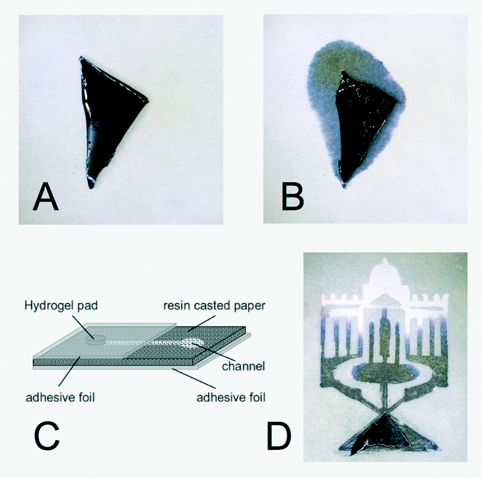 | ||
| Fig. 1 Responsive hydrogels drive fluid flow in paper substates. (A) Swollen thermoresponsive hydrogel on a paper substrate loaded with black ink. (B) The same hydrogel as in (A) after a temperature-induced collapse. The black ink was released and has entered the paper substrate, driven by capillary forces. (C) Cartoon illustrating the combination of a hydrogel with a structured paper substrate. (D) Collapsed hydrogel (bottom) that has released black ink into a paper-based microfluidic structure, shaped to the University of Potsdam logo. | ||
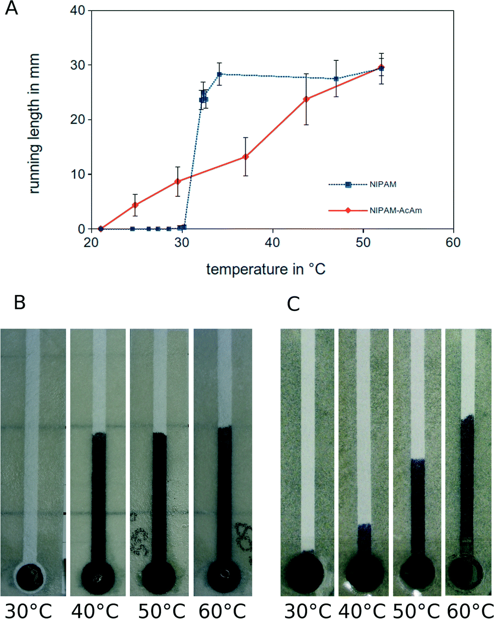 | ||
| Fig. 2 Control of fluid run length in a paper-based microchannel. (A) Fluid run length as a function of temperature for a NIPAM (blue) and a NIPAM-AcAm hydrogel (red). Mean values and standard deviations are shown, measurements were repeated 7 times (blue curve) and 6 times (red curve). (B) Images displaying the switch-like liquid release from a NIPAM hydrogel at different temperatures. (C) Images illustrating the gradual linear release from a composite NIPAM-AcAm hydrogel at different temperatures. | ||
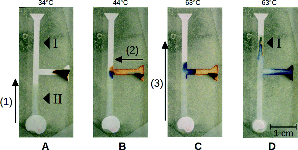 | ||
| Fig. 3 Sequential acid–base reaction performed by hydrogel-driven paper-based microfluidics in a T-channel structure with two reservoirs. The NIPAM-AcAm hydrogel at the bottom is loaded with water and shows a linear collapse behavior. The NIPAM hydrogel at the right is loaded with thymol blue indicator and shows a switch-like collapse. At the positions indicated by triangular arrows in panel (A), citric acid (I) and sodium hydroxide (II) are placed. (A) The hydrogel at the bottom is heated to 34 °C, resulting in a partial release of liquid (1) to dissolve the NaOH at position (II). (B) The NIPAM hydrogel on the right is heated to 44 °C in order to release the thymol blue indicator (2). When coming into contact with the NaOH at the T-junction, a color change to blue clearly indicates the high pH-value of the NaOH solution. (C and D) The NIPAM-AcAm hydrogel at the bottom is heated to 63 °C to induce a second release of liquid that pushes the sodium hydroxide solution further up the channel (3). When coming into contact with the citric acid deposited at position (I), a change of the indicator back to orange is observed at the interface of the blue NaOH front, indicating a drop in pH-value. | ||
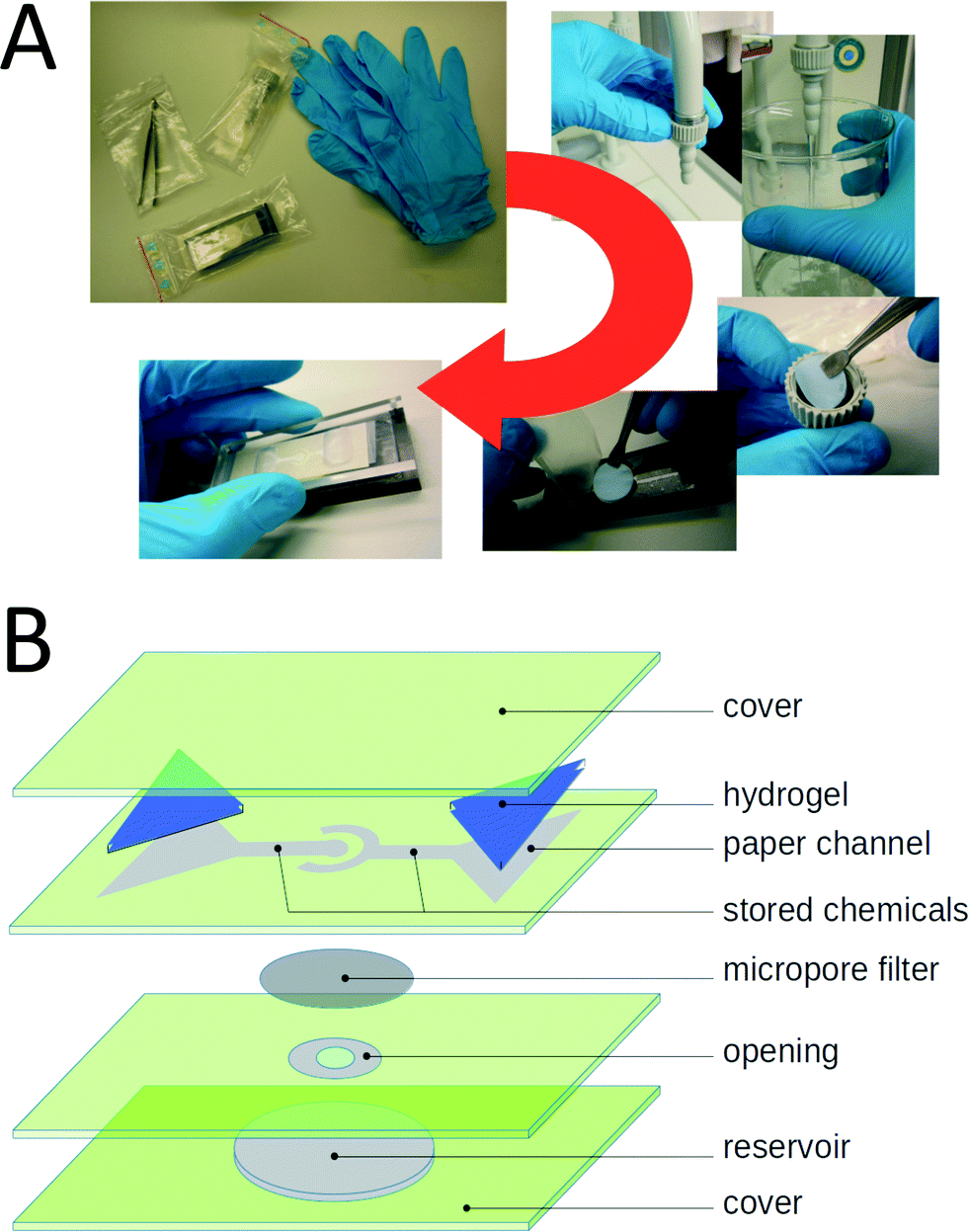 | ||
| Fig. 4 Overview of the antibody-based E. coli test assay, driven by hydrogels on a paper-based microfluidic device. (A) Handling of the test kit, showing the different components, the acquisition of the tap water sample, and the insertion of the micro-pore filter into the paper fluidic chip. (B) Overview of the layer structure of the paper fluidic chip, indicating the hydrogel reservoirs, the channel geometry, and the position of the micro-pore filter. | ||
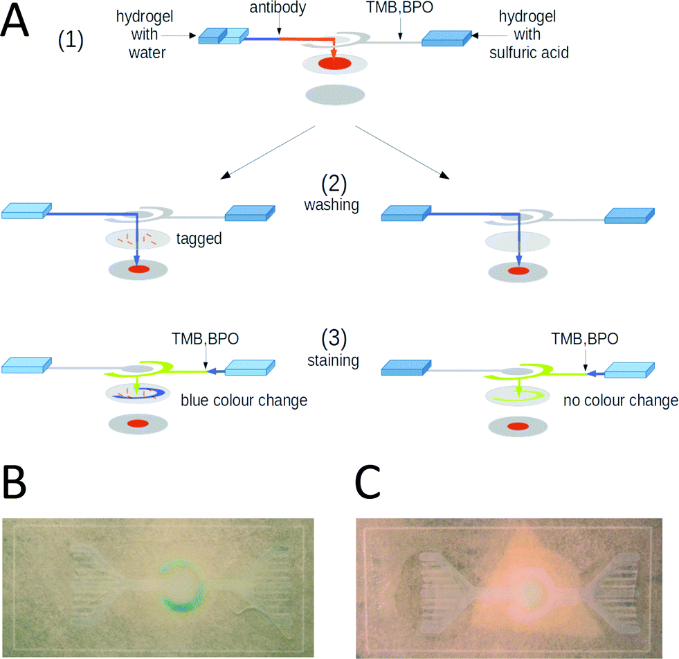 | ||
| Fig. 5 Operation of the hydrogel-driven paper fluidic E. coli test assay. (A) Flow chart illustrating the steps of operation of the device, (1) release of the antibody, (2) washing of the sample, and (3) release of the color indicator. Left and right hand sides show positive and negative tests respectively. (B) Photograph of a paper-based microfluidic E. coli test chip showing a positive response, indicated by the blue ring. (C) Photograph of a paper-based microfluidic E. coli test chip showing a negative response. | ||
Afterwards, a piece of swollen hydrogel was dried on a paper tissue. All water from the surfaces of the hydrogel was removed to make sure that no liquid is released in contract with the paper substrate prior to the collapse. The hydrogel was first cut into squares pads with a side length of 1 cm. Then two triangular pieces of hydrogel were produced from each pad by cutting it in half along its diagonal. The triangular pads were placed on the reservoir areas of the structured paper and fixed with a polyethylene adhesive tape, see Fig. 4B. To release the liquid from the hydrogel pads, they were heated up to 32 °C on a small Peltier-based hot plate.
3. Results and discussion
3.1 Hydrogels are versatile reservoirs to drive paper-based microfluidics
A swollen hydrogel can incorporate considerable amounts of aqueous liquid. In the case of a thermoresponsive NIPAM hydrogel, a fraction of 85% weight percent of aqueous solution is easily obtained in the swollen state. The liquid is tightly encapsulated in the swollen hydrogel. In contact with a dry paper substrate, no liquid is released from the swollen NIPAM hydrogel. For long-term storage hydrogel-based devices need to be wrapped in a water-impermeable sealing. Without sealing, the hydrogels will gradually dry out and will release less water during operation. Alternatively, without perfect sealing, the hydrogels can be stored at reduced temperatures to prevent drying. For example, at 6 °C the swollen hydrogels can be stored for at least three months without any problems.If the temperature is increased above the lower critical solution temperature (LCST) of the thermoresponsive hydrogel, it collapses. For the NIPAM hydrogel used here, an LCST of 31 °C was reported.21 Upon collapse, the encapsulated liquid is released. It will be taken up and transported into the paper by capillary forces. In Fig. 1A and B, this is demonstrated for a NIPAM hydrogel pad that was loaded with black ink. Following the well-established photolithographic techniques that are widely used to create the structured substrates for paper-based microfluidics, the capillary-driven fluid flow in the paper substrate can be localized and guided through arbitrary complex geometries, see Fig. 1C for a schematic representation of the approach and Fig. 1D for an example.
As long as liquid is supplied to the paper, the fluid front is extending into the channels. Once the reservoir is depleted, the capillary-driven fluid flow stops. For a straight channel of 2 mm in width, the distance over which the fluid front moves into the channel depends linearly on the amount of supplied liquid for volumes up to 10 μl. Beyond 10 μl, the dependence of the run length on the liquid volume becomes nonlinear and saturates due to increased liquid evaporation from the inlet area, see Fig. S1 in the ESI† for an example. Liquid evaporation and the resulting saturation of the liquid run length for larger applied volumes limits the channel length over which such fluidic devices can be reliably operated. For a channel width of 2 mm as was used in our experiments, the operational distance is about 3 cm.
By applying different amounts of liquid between 1 and 10 μl, the linear dependence of the distance traveled by the liquid front (fluid run length) and the supplied volume can be clearly seen, see Fig. S1† (note that 0.5 μl are consumed to fill the circular inlet area of the channel, before the fluid entered the actual channel). In the linear regime, the weight of a hydrogel pad required to achieve a defined run length can be calculated. However, as the paper-based microfluidic devices are operated with small amounts of liquid (in the microliter range), care has to be taken to prevent evaporation also when hydrogels are used, in particular at increased temperatures. This can be achieved by sealing the fluidic system with a water impermeable adhesive foil. Finally, we would like to point out that a wide range of responsive hydrogels is available, that can be triggered by different physical and chemical stimuli, for example, changes in the pH value,40,41 UV-irradiation,42,43 or specific ligand concentrations.44,45 Thus, due to the versatile chemistry of responsive hydrogels, many different variants of this principle of hydrogel-driven fluid release can be implemented.
3.2 Composite hydrogels can be tailored to achieve controlled release of liquid
The thermoresponsive NIPAM hydrogel used above shows a complete collapse within a narrow temperature window between 28 and 34 °C. Upon an increase in temperature, the microstructured paper substrate thus experiences an irreversible, switch-like fluid release. Even though this will be of interest for many fluidic tasks, more complex applications may require a gradually controlled release of liquid. This can be achieved by exchanging the pure NIPAM hydrogel for a composite material containing different types of monomers.46,47 Depending on the ratio of monomers, the characteristics of the collapse may be changed from a narrow, switch-like transition to a linear gradual collapse that extends over a wide temperature window.Here, we demonstrate this idea using hydrogels that are made from a mixture of NIPAM and Acrylamide (AcAm) monomers. In contrast to the pure NIPAM hydrogel, the collapse of the NIPAM-AcAm hydrogel extends to higher temperatures and shows a gradual, linear temperature dependence, see Fig. S2 in the ESI† for the results of a bulk experiment. We attribute this behavior to the influence of the acrylamide groups in the hydrogel network. They exhibit an increased number of possibilities for hydrogen bond formation with adjacent water molecules. Thus, more thermal energy is required to expel the water from the network, resulting in a broader temperature range over which the fluid is released. Only at 60 °C, the completely collapsed state is reached, where the weight of the hydrogel is reduced by 85% as compared to the swollen state.
Due to the different collapse characteristics of NIPAM and NIPAM-AcAm, it is possible to switch between an all-or-none and a gradual fluid release, as is demonstrated in Fig. 2 for a linear paper-based microchannel. Because of the linear collapse behaviour it is possible to control the fluid run length in the channel by tuning the temperature of the NIPAM-AcAm hydrogel.
3.3 Structured paper substrates and hydrogel reservoirs can be combined to implement multi-step chemical protocols
By combining structured paper substrates and hydrogel reservoirs, we can design microfluidic devices to implement multi-step chemical protocols. Inside the hydrogel reservoirs, well-defined volumes of different components can be stored and released according to a predefined temporal workflow. Additionally, chemicals or enzymes can be stored under dry conditions in the paper substrate, where they will be dissolved upon a release of liquid from one of the hydrogel reservoirs. In particular, hydrogels that display a gradual linear collapse can be combined in the same device with hydrogels that release liquid in a switch-like fashion to achieve different flow speeds. In this way, we can control the residence time of solutions in different parts of the device to achieve optimal reaction conditions.In the following example, a simple acid–base reaction is implemented to demonstrate the flexible design principles of this approach. Note that this device is not intended for practical use in point-of-care diagnostics but rather serves as an academic test case to demonstrate the performance of our technique. The layout of the channel structure used here can be seen in Fig. 3. Different parts of the structure were loaded with citric acid at position (I) and sodium hydroxide solution at (II) and dried at room temperature. To drive fluid flow inside the paper channel, hydrogel reservoirs were placed on the different inlet regions of the device. On the one hand, we placed a NIPAM-AcAm hydrogel that shows a linear collapse characteristic over a wide temperature range on the bottom inlet region. On the other hand, a NIPAM hydrogel, loaded with thymol blue indicator, was placed on the inlet region of the side channel to the right.
At the beginning (Fig. 3A), we induced a partial collapse of the NIPAM-AcAm hydrogel by heating up to a temperature of 34 °C. In this way, part of the water that was stored inside the swollen hydrogel was released into the paper channel (1). The collapse temperature was chosen such that the channel was filled only up to the T-junction, so that the sodium hydroxide at position (II) was dissolved. In a second step (Fig. 3B), we heated the NIPAM hydrogel at the inlet of the side channel up to a temperature of 44 °C. This resulted in a complete collapse and a release of the entire volume of thymol blue solution into the channel (2). The solution filled the side channel up to the T-junction, where it was mixed with the sodium hydroxide solution from the bottom channel. At this location, a clear color change of the thymol blue from orange to blue was observed, indicating the high pH value of the sodium hydroxide solution. Finally (Fig. 3C and D), the temperature of the NIPAM-AcAm gel was further increased to 63 °C, so that the remaining fluid was released into the channel and pushed the fluid further towards the upper outlet (3). Due to the presence of citric acid at position (I) in the upper part of the channel, the color of the indicator at the edge of the blue sodium hydroxide front changed back to orange, clearly showing a drop in the pH value.
3.4 A hydrogel-driven E. coli test
In the previous section, we demonstrated that chemicals could be stored under dry conditions in a paper channel and taken up into solution again by liquid released from a hydrogel reservoir. Not only simple non-biological substances but also proteins can be safely stored under dry conditions for extended periods of time (typically by lyophilization). Here, we show that these storage properties can be used to create an efficient paper-based E. coli test system.We designed a hydrogel-driven assay to detect E. coli infections in tap water. A micro-pore filter with a pore size of 0.2 μm is inserted at the tap outlet and a given volume of water is run through the filter. Subsequently, the filter is removed from the tap and inserted into the paper fluidic assay, which finally produces a color reaction if E. coli bacteria are present. The handling of the assay is depicted in Fig. 4A. In Fig. 4B, an overview of the layered structure of the paper fluidic device is shown, indicating the channel geometry, as well as the positions of the hydrogel reservoirs and the micro-pore filter.
The assay is based on a polyclonal antibody against the K99 pili of E. coli. The antibody is labeled at the NH-terminus with the enzyme horseradish-peroxidase (HRP). The layout of the paper fluidic device is schematically illustrated in Fig. 5A. The paper channels were loaded with antibody, BPO and TMB as described in section 2.7. A water loaded hydrogel pad was placed on the reservoir field of the inner paper channel and a second hydrogel pad loaded with 100 μM sulfuric acid was placed on the reservoir field of the outer circular paper channel. The micro-pore filter was exposed to the sample liquid and dried at room temperature. For testing the function of the assay 1 ml of an E. coli containing water test sample with a cell density of 2.8 × 10⁻⁵ cells per ml was passed through the micro-pore filter. Afterwards, the filter was loaded into the test assay between the channel layer and the reservoir paper as shown in Fig. 4A.
The operation steps of the paper fluidic chip are illustrated in Fig. 5A. In a first step, the water containing hydrogel was heated up to 38 °C. After 10 s, the hydrogel had released half of its water content and the heating was stopped. The released water was drawn into the paper channel by capillary forces, dissolved the E. coli antibody in the channel, and the fresh antibody solution reached the micro-pore filter as shown in Fig. 5A (1). In a second step, the same hydrogel was heated up to 38 °C again, so that it compacted completely, the remaining water was released, and washed the channel structure and the micro-pore filter as shown in Fig. 5A (2). If the target bacteria were present on the micro-pore filter, the labeled antibody attached to the pili of the microorganisms. In the last step the second hydrogel pad containing the sulfuric acid was heated up to 38 °C, so that the BPO and the TMB were dissolved and also directed to the micro-pore filter via the outer ring-shaped paper channel, see Fig. 5A (3). If microorganisms marked by the antibody were present, the color changed from yellow to blue as shown in Fig. 5B. In the absence of an E. coli contamination (control experiment), i.e. when no bacteria were present on the micro-pore filter, the antibody was washed to the paper pad in the bottom layer below the micro-pore filter and no color reaction was initiated by the release of BPO and TMB, see the right hand side of Fig. 5A. In this case, no color change was visible, see Fig. 5C.
Established assays to probe for bacterial contamination of drinking water also use micro-pore filters to localize the contaminants. However, they rely on subsequent incubation of the samples on nutrient agar and identify the infections via the growth of bacterial colonies. In those assays, typically 250 ml are passed through the micro-pore filter. If more than 100 colonies are found, the water is classified as non-potable. Our assay requires at least 104 bacteria on the micro-pore filter to reliably yield a positive result. Thus, a total volume of 25 L has to pass through the micro-pore filter in order to detect the same critical level of contamination.
We emphasize that the established assays require a fully equipped microbiology laboratory for sample incubation and take up to several days. In contrast, our novel test system provides an immediate answer that is available within minutes and directly on site, without the need of a laboratory environment. We furthermore point out that this test assay can be readily adapted to detect other bacterial contaminants, given that the corresponding antibodies are available.
4. Conclusion
In this article, we demonstrated that swollen thermoresponsive hydrogels can be used as reservoirs to drive microfluidics in structured paper tissues. The distance over which the fluid runs along a given paper channel can be controlled by the amount of released liquid. Using composite hydrogels that are produced by polymerizing a mixed solution of NIPAM and Acrylamide monomers, we can precisely adjust the collapse behavior and thus the liquid release. We showed that with this approach, we can implement chemical protocols consisting of multiple reaction steps on paper substrates, where different chemical components are released to react with each other according to a predefined sequence. Finally, we exemplified this principle by designing an antibody-based paper fluidic assay to test for E. coli contaminations of drinking water. Required chemicals as well as the indicator components were stored on the paper substrate. Immediately before performing the test, liquid was introduced into the structured paper by temperature-induced collapse of two hydrogel reservoirs. The liquid dissolved and premixed the components of the assay, producing a ready to use test system.In summary, by combining structured paper tissues with thermoresponsive hydrogels, versatile low cost and easy to use paper fluidic test systems can be produced for a wide range of analytical tasks. All required chemical components can be stored either on the paper substrate or inside the hydrogel pads. They can be dissolved and mixed to initiate chemical reactions by releasing liquid from the hydrogel reservoirs according to a predefined protocol. We would like to stress that these systems are perfectly suited for operation outside and independent of high-tech laboratories, like point-of-care diagnostics in remote places or developing countries. These systems offer touch-less control and can be encapsulated with robust foil or other coatings. No high-precision fluidic pumps are required to operate such test systems. Instead, we propose the combination with simple, hand-held devices that execute the localized and sequential heating of the different hydrogel reservoirs on the chip. This can be easily achieved by an array of small battery-driven Peltier elements. For hydrogels with a precisely tuned transition temperature, one may even envision that the collaps is induced by the body temperature of the operator upon contact. Moreover, we stress that this approach is not limited to temperature-sensitive hydrogels but may be easily extended to other responsive hydrogels that are sensitive to changes in pH-value or to the presence of certain ligands.
Acknowledgements
We thank the Bundesministerium für Bildung und Forschung (BMBF) for funding in the framework of the Impulszentrum für integrierte Bioanalyse (Taschentuchlabor).References
- Y. Zeng and T. Wang, Anal. Bioanal. Chem., 2013, 405, 5743–5758 CrossRef CAS PubMed.
- S. J. Maerkl, Curr. Opin. Biotechnol., 2011, 22, 59–65 CrossRef CAS PubMed.
- K. Ohno, K. Tachikawa and A. Manz, Electrophoresis, 2008, 29, 4443–4453 CrossRef CAS PubMed.
- D. C. Duffy, J. C. McDonald, O. J. A. Schueller and G. M. Whitesides, Anal. Chem., 1998, 70, 4974–4984 CrossRef CAS PubMed.
- T. Deng, H. Wu, S. T. Brittain and G. M. Whitesides, Anal. Chem., 2000, 72, 3176–3180 CrossRef CAS.
- P. Yager, T. Edwards, E. Fu, K. Helton, K. Nelson, M. R. Tam and B. H. Weigl, Nature, 2006, 442, 412–418 CrossRef CAS PubMed.
- C. D. Chin, V. Linder and S. K. Sia, Lab Chip, 2007, 7, 41–57 RSC.
- A. W. Martinez, S. T. Phillips, B. J. Wiley, M. Gupta and G. M. Whitesides, Lab Chip, 2008, 8, 2146 RSC.
- A. W. Martinez, S. T. Phillips, M. J. Butte and G. M. Whitesides, Angew. Chem., 2007, 119, 1340–1342 CrossRef PubMed.
- A. W. Martinez, S. T. Phillips, E. Carrilho, S. W. Thomas, H. Sindi and G. M. Whitesides, Anal. Chem., 2008, 80, 3699–3707 CrossRef CAS PubMed.
- P. Lisowski and P. K. Zarzycki, Chromatographia, 2013, 76, 1201–1214 CAS.
- W. L. Then and G. Garnier, Rev. Anal. Chem., 2013, 32 Search PubMed.
- A. W. Martinez, S. T. Phillips and G. M. Whitesides, Proc. Natl. Acad. Sci. U. S. A., 2008, 105, 19606–19611 CrossRef CAS PubMed.
- K. Abe, K. Suzuki and D. Citterio, Anal. Chem., 2008, 80, 6928–6934 CrossRef CAS PubMed.
- A. W. Martinez, S. T. Phillips, G. M. Whitesides and E. Carrilho, Anal. Chem., 2010, 82, 3–10 CrossRef CAS PubMed.
- R. Pelton, TrAC, Trends Anal. Chem., 2009, 28, 925–942 CrossRef CAS PubMed.
- P. Kwong and M. Gupta, Anal. Chem., 2012, 84, 10129–10135 CrossRef CAS PubMed.
- S. Raymond and L. Weintraub, Science, 1959, 130, 711 CAS.
- M. L. White, J. Phys. Chem., 1960, 64, 1563–1565 CrossRef CAS.
- S. W. Kim, Y. H. Bae and T. Okano, Pharm. Res., 1992, 9, 283–290 CrossRef CAS.
- M. Heskins and J. E. Guillet, J. Macromol. Sci., Chem., 1968, 2, 1441–1455 CrossRef CAS.
- S. Rimmer, I. Soutar and L. Swanson, Polym. Int., 2009, 58, 273–278 CrossRef CAS PubMed.
- C.-K. Chee, S. Rimmer, I. Soutar and L. Swanson, Polym. Int., 2006, 55, 740–748 CrossRef CAS PubMed.
- I. C. Barker, J. M. G. Cowie, T. N. Huckerby, D. A. Shaw, I. Soutar and L. Swanson, Macromolecules, 2003, 36, 7765–7770 CrossRef CAS.
- D. C. Harsh and S. H. Gehrke, J. Controlled Release, 1991, 17, 175–185 CrossRef CAS.
- H. Kawaguchi, K. Fujimoto and Y. Mizuhara, Colloid Polym. Sci., 1992, 270, 53–57 CAS.
- T. G. Park and A. S. Hoffman, J. Polym. Sci., Part A: Polym. Chem., 1992, 30, 505–507 CrossRef CAS PubMed.
- X. S. Wu, A. S. Hoffman and P. Yager, J. Polym. Sci., Part A: Polym. Chem., 1992, 30, 2121–2129 CrossRef CAS PubMed.
- T. G. Park and A. S. Hoffman, J. Appl. Polym. Sci., 1992, 46, 659–671 CrossRef CAS PubMed.
- D. Walsh, S. R. Hall, A. Moir, S. C. Wimbush and B. Palazzo, Biomacromolecules, 2007, 8, 3800–3805 CrossRef CAS PubMed.
- A. K. Agarwal, L. Dong, D. J. Beebe and H. Jiang, Lab Chip, 2007, 7, 310 RSC.
- B. R. Saunders and B. Vincent, J. Chem. Soc., Faraday Trans., 1996, 92, 3385–3389 RSC.
- C. K. Chiklis and J. M. Grasshoff, J. Polym. Sci., Polym. Phys. Ed., 1970, 8, 1617–1626 CAS.
- Y. H. Bae, T. Okano, R. Hsu and S. W. Kim, Makromol. Chem., Rapid Commun., 1987, 8, 481–485 CrossRef CAS PubMed.
- A. Afrassiabi, A. S. Hoffman and L. A. Cadwell, J. Membr. Sci., 1987, 33, 191–200 CrossRef CAS.
- G. Fu and W. O. Soboyejo, Mater. Sci. Eng., C, 2011, 31, 1084–1090 CrossRef CAS PubMed.
- Y. Okuyama, R. Yoshida, K. Sakai, T. Okano and Y. Sakurai, J. Biomater. Sci., Polym. Ed., 1993, 4, 545–556 CrossRef CAS PubMed.
- A. D'Emanuele and R. Dinarvand, Int. J. Pharm., 1995, 118, 237–242 CrossRef.
- Z.-L. Ding, M. Yoshida, M. Asano, Z.-T. Ma, H. Omichi and R. Katakai, Radiat. Phys. Chem., 1994, 44, 263–272 CrossRef CAS.
- O. E. Philippova, D. Hourdet, R. Audebert and A. R. Khokhlov, Macromolecules, 1997, 30, 8278–8285 CrossRef CAS.
- Y. Tao, J.-X. Zhao and C.-X. Wu, J. Appl. Polym. Sci., 2006, 101, 323–330 CrossRef CAS PubMed.
- H. Komatsu, S. Tsukiji, M. Ikeda and I. Hamachi, Chem. – Asian J., 2011, 6, 2368–2375 CrossRef CAS PubMed.
- L. A. Wells, M. A. Brook and H. Sheardown, Macromol. Biosci., 2011, 11, 988–998 CrossRef CAS PubMed.
- J. Buller, A. Laschewsky, J.-F. Lutz and E. Wischerhoff, Polym. Chem., 2011, 2, 1486 RSC.
- S. Inal, J. D. Kölsch, F. Sellrie, J. A. Schenk, E. Wischerhoff, A. Laschewsky and D. Neher, J. Mater. Chem. B, 2013, 1, 6373 RSC.
- C. K. Chiklis and J. M. Grasshoff, J. Polym. Sci., Part A: Polym. Chem., 1970, 8, 1617 CrossRef CAS PubMed.
- G. Dalkas, K. Pagonis and G. Bokias, Polymer, 2006, 47, 243 CrossRef CAS PubMed.
Footnote |
| † Electronic supplementary information (ESI) available. See DOI: 10.1039/c5lc00276a |
| This journal is © The Royal Society of Chemistry 2015 |