 Open Access Article
Creative Commons Attribution 3.0 Unported Licence
Rapid and simple preparation of thiol–ene emulsion-templated monoliths and their application as enzymatic microreactors†
Josiane P.
Lafleur
*a,
Silja
Senkbeil
a,
Jakub
Novotny
bc,
Gwenaël
Nys
d,
Nanna
Bøgelund
a,
Kasper D.
Rand
a,
Frantisek
Foret
c and
Jörg P.
Kutter
a
aDepartment of Pharmacy, University of Copenhagen, Copenhagen, Denmark. E-mail: Josiane.lafleur@sund.ku.dk; Tel: (+45) 3532 0398
bDepartment of Biological and Biochemical Sciences, University of Pardubice, Pardubice, Czech Republic
cInstitute of Analytical Chemistry of the ASCR, v.v.i., Brno, Czech Republic
dDepartment of Pharmacy, Université de Liège, Liège, Belgium
First published on 27th March 2015
Abstract
A novel, rapid and simple method for the preparation of emulsion-templated monoliths in microfluidic channels based on thiol–ene chemistry is presented. The method allows monolith synthesis and anchoring inside thiol–ene microchannels in a single photoinitiated step. Characterization by scanning electron microscopy showed that the methanol-based emulsion templating process resulted in a network of highly interconnected and regular thiol–ene beads anchored solidly inside thiol–ene microchannels. Surface area measurements indicate that the monoliths are macroporous, with no or little micro- or mesopores. As a demonstration, galactose oxidase and peptide-N-glycosidase F (PNGase F) were immobilized at the surface of the synthesized thiol–ene monoliths via two different mechanisms. First, cysteine groups on the protein surface were used for reversible covalent linkage to free thiol functional groups on the monoliths. Second, covalent linkage was achieved via free primary amino groups on the protein surface by means of thiol–ene click chemistry and L-ascorbic acid linkage. Thus prepared galactose oxidase and PNGase F microreactors demonstrated good enzymatic activity in a galactose assay and the deglycosilation of ribonuclease B, respectively.
Introduction
High surface area materials are essential in many chemical, biological and analytical procedures. They can be used as solid supports for biomolecules in enzymatic microreactors,1–3 as stationary phases in chromatography4,5 and in sample preparation steps such as extraction and pre-concentration.6 Commercially, sorbents are available as micrometer-sized beads made of materials such as silica or agarose, which can either be bought pre-packed into columns or packed manually. Optimal packing is not trivial to achieve and in practice, even the best packed columns contain 30–40% void volume in addition to the internal porosity of the beads.7 Packing columns in microfluidic chips is even more challenging. Porous polymer monoliths offer an attractive alternative to traditional packed beds. The processability of polymers can be used to easily generate porous monoliths and beads from a mixture of monomers, free radical initiators and porogenic solvents. Heterogeneous emulsions consisting of at least one immiscible liquid dispersed in another in the form of droplets can be used as templates for the production of porous materials, so-called emulsion-templated monoliths, where either the dispersed or continuous phase is polymerized.8 In the case of high internal phase emulsion templated monoliths (polyHIPEs), the internal phase (usually forming more than 74% v/v of the emulsion), is dispersed as discrete droplets within a continuous, less abundant external phase.9 These monolithic materials can be prepared using a very simple process carried out within the confines of a closed container, such as a microfluidic channel. However, routine applications in microfluidic devices still face some challenges. Poor adhesion of the monolith inside native unmodified polymeric microchannels and monolith shrinkage are recurring problems. This can cause a formed monolith to detach from the microchannel walls and create, for example, large dead volumes. Therefore, the preparation of porous polymer monoliths and their anchoring inside microfluidic channels is still an active area of research.The attractive surface properties of thiol–ene (TE) polymers combined with their ease of processing have made them an increasingly popular choice in the fabrication of microfluidic devices for bioanalytical applications. Microfluidic devices have been fabricated with commercially available TE-based photo-curable adhesives (NOA, Norland Optical Adhesives, Norland Products Inc, USA)10–16 as well as with custom formulations prepared in-house. Alterations in the nature and/or stoichiometry of reactants in customized formulations provide increased control over elastic modulus17 and surface chemistry.18 Carlborg et al.19 introduced a new class of TE materials, “off-stoichiometry” TE (OSTE), achieved by altering extensively the stoichiometric ratios of the initial reactant monomers. The result is a large excess of functional groups, either thiols or enes, on the polymer surfaces and marked variations in material bulk properties. The functional groups present at the surface of OSTE polymers have been used as anchors for the covalent attachment of biomolecules20,21 and for bonding.22,23
Although TE-based microfluidic devices have received a high level of attention in recent years, the ability of TE polymers to form in-chip porous monoliths remains unexplored. The advantages of TE and OSTE in the preparation of monoliths are numerous. The tunable OSTE surface chemistry can provide for a simple means of covalently anchoring monoliths to microchannel walls without any prior surface activation as well as for a wide variety of photoinitiated functionalization reactions to occur at the surface of the monoliths. Moreover, the TE click chemistry reaction24–26 offers high atom economy, a large thermodynamic driving force and simple/mild reaction conditions27 as well as bio-orthogonality,28 making it an ideal reaction scheme for the immobilization of biomolecules on solid supports.20,21,29
Immobilized enzyme microreactors are especially interesting since these tend to exhibit much higher efficiency compared to the corresponding reactions in solution.2 A wide variety of chemical reactions are available for the immobilization of biomolecules to TE solid supports. TE click chemistry allows for simple and rapid photoinitiated modification of the solid support for the covalent irreversible linkage of proteins through their amino groups. Additionally, many enzymes and proteins possess free thiol groups at their surface, which are available for interactions with the thiol groups present at the surface of OSTE monoliths, allowing their straightforward and reversible immobilization through direct disulfide linkage. Finally, in proteins where cysteine residues form intramolecular disulfide bonds, immobilization can proceed through thiol–disulfide exchange30,31 or photonic activation of disulfide bridges.32 The thiol–disulfide exchange chemistry offers several advantages as covalent disulfide bonds can form efficiently at neutral pH in aqueous solutions and can be easily reversed with a reducing agent33 for the regeneration of the microreactor. TE and thiol–yne (TY) polyHIPEs have been prepared in bulk,34–38 with functional monomers added in situ35,37 or in a post-functionalization step performed on the ground monolith powder.38 Droplet-based microfluidic devices have been used to prepare NOA porous polymer microspheres39 as well as macroporous and non-porous TE/TY polymer beads.40 In both cases, droplets were cured individually and collected as beads from the microfluidic device. Finally, Liu et al. used TE41 and TY42 photoinduced polymerization for the preparation of macroporous monoliths in fused-silica capillaries for liquid chromatography.
The method reported here allows monolith synthesis and anchoring inside TE microchannels in a single and rapid photoinitiated step. We demonstrate that the thus prepared monoliths can be post-functionalized reversibly through the formation of disulfide bonds with enzymes or permanently using further photoinitiated TE click chemistry to establish an irreversible covalent linkage to enzymes via their free amino groups. As a demonstration, enzymatic microreactors featuring immobilized galactose oxidase and PNGase F were prepared and characterized by performing a galactose assay and the deglycosylation of ribonuclease B, respectively.
Experimental
Reagents
Pentaerythritol-tetrakis(3-mercaptopropionate) (“tetrathiol”), triallyl-1,3,5-triazine-2,4,6(1H,3H,5H)-trione (“triallyl”), 2-(boc amino)ethanethiol, L-ascorbic acid (ASA), galactose-oxidase from Dactylium dendroides [50 U ml−1], horseradish peroxidase (HRP, lyophilized powder, 150 U mg−1), PNGase F, ninhydrin, D-galactose, D-(+)-glucose, ribonuclease B (RNase B from bovine pancreas (50 Kunitz units per mg protein)), 10-acetyl-3,7-dihydroxyphenoxazine (ADHP), Tween 20 and 5,5′-dithiobis(2-nitrobenzoic acid) (DTNB) were obtained from Sigma Aldrich (Brøndby, DK). Lucirin TPO-L (ethyl-2, 4, 6-trimethylbenzoylphenyl phosphinate) was obtained from BASF (Hardmatt, CH). Sylgard 184 – poly(dimethylsiloxane) (PDMS) elastomer kit was obtained from Dow Corning (Midland, MI, USA). Hypermer B246 and Span 80 surfactants were obtained from Croda International Plc (Snaith, UK)Device fabrication
A two-step replica molding process was used to fabricate the chips. Chip designs were drawn with computer-aided-design software (Autodesk Inventor Professional 2014, San Rafael, CA, USA). The devices featured channels 500 μm wide by 200 μm deep. Chips used for fluorescence measurements featured an 800 μm deep detection chamber. The internal volume of the chips was 5 μl. Micromilled poly(methylmethacrylate) (PMMA) masters as well as poly(tetrafluoroethylene) chip holders featuring injection ports were manufactured by high precision milling (Minitech 3, Minitech Machinery Corp., Norcross, GA, USA). PDMS molds for TE casting were prepared from the PMMA masters and cured at 80 °C for 2 hours.The TE monomers (tetrathiol and triallyl) were mixed in various stoichiometric ratios and poured into PDMS molds prior to exposure to UV light (25 s, 160 mW cm−2 at 365 nm, Dymax EC 5000 Series UV curing flood lamp, Dymax Corp, Torrington, CT). After curing, the TE parts were peeled off from the soft PDMS molds. No photoinitiator was used to minimize chip auto-fluorescence. The absence of photoinitiator was compensated for by the high output of the UV flood lamp at wavelengths below 300 nm. Microfluidic chips were bonded immediately after production, while a thin layer of uncured TE is still present at the surface of the TE parts due to the short exposure time and slight oxygen inhibition in the absence of photoinitiator. Prior to bonding, the TE parts were warmed up for 10 minutes in an oven at 80 °C and placed in conformal contact. A slight pressure was applied on the assembly to ensure uniform sealing and it was exposed to UV light (2 × 1 min, 160 mW cm−2 at 365 nm) for bonding. The bonded microfluidic chip was placed in an oven under a weight (80 °C for 2 hours) and allowed to cool overnight before use. The final heating step helps keep the parts soft and in contact with each other to further enhance the bonding.
Monoliths preparation
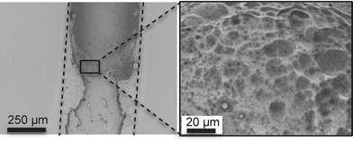
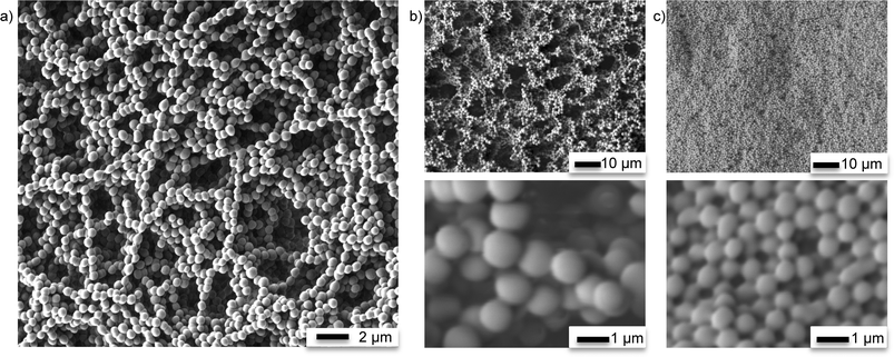
Two different types of emulsions were prepared in order to form various in-chip TE monoliths (Fig. 1). The emulsions were prepared with either water or methanol as the porogen, resulting in markedly different monolith morphologies. The monomeric composition of the organic phase of the emulsions consisted of stoichiometric TE (S-TE), off-stoichiometric TE featuring 40% excess thiol groups (OSTE-thiol) or off-stoichiometric TE featuring 40% excess allyl groups (OSTE-allyl). The monolith formation conditions are summarized in Table 1.| Stirring conditions | Stirring time | Porogen | Surfactant | Polymer phase | Experiments performed |
|---|---|---|---|---|---|
| a Magnetic stirring. b Overhead stirring. c Dropwise addition of water and stirred until the water was fully incorporated into the emulsion. | |||||
| Interconnected beads (polymerized dispersed phase) | |||||
| MSa 40% of max. speed | 1 min | 60% w/w methanol | None | S-TE OSTE-allyl OSTE-thiol | Specific surface area |
| MSa 40% of max. speed | 1 min | 80% w/w methanol | None | S-TE OSTE-allyl OSTE-thiol | Specific surface area, SEM, enzyme immobilization, removal of enzymes bound through thiols with TCEP |
| MSa 60% of max. speed | 1 min | 80% w/w methanol | None | S-TE OSTE-allyl OSTE-thiol | SEM |
| PolyHIPE (polymerized continuous phase) | |||||
| MSa 40% of max. speed | 3–10 minc | 75% w/w water | 10% w/w Span 80 | S-TE + 50% w/w CHCl3 | (Unstable emulsions) |
| MSa 40% of max. speed | 3–10 minc | 80% w/w water | 3% w/w Span 80 | S-TE + 50% w/w CHCl3 | (Unstable emulsions) SEM |
| MSa 40% of max. speed | 3–10 minc | 80% w/w water | 20% w/w Span 80 | S-TE + 50% w/w CHCl3 | (Unstable emulsions) |
| OHb 500 rpm | 3–10 minc | 80% w/w water | 10% w/w Span 80 | S-TE + 50% w/w CHCl3 | (Unstable emulsions) |
| OHb 500 rpm | 3–10 minc | 75% w/w water | 10% w/w Hypermer B246 | S-TE + 50% w/w CHCl3 | (Unstable emulsions) |
| OHb 300 rpm | 3–10 minc | 80% w/w water | 3% w/w Hypermer B246 | S-TE + 50% w/w CHCl3 | (Unstable emulsions) |
Monoliths characterization
Thiol surface density
The surface thiol density was quantitated using DTNB in a protocol adapted from Ellman's procedure for quantifying free sulfhydryl group in solution44 and described elsewhere.20 Briefly, thiol–ene slabs (20 mm × 20 mm × 0.5 mm, 60% excess allyl − 60% excess thiols) were immersed in 5,5′-dithiobis(2-nitrobenzoic acid) (0.08 mg mL−1 in 0.1 M sodium phosphate buffer, pH 8.0). After 10 minutes, the thiol–ene slab was removed and the absorbance of the solution was measured at 412 nm. The number of thiols on the surface of the thiol–ene slabs was evaluated from the molar extinction coefficient of TNB2− (14![[thin space (1/6-em)]](https://www.rsc.org/images/entities/char_2009.gif) 150 M−1 cm−1).45
150 M−1 cm−1).45
Enzyme immobilization
Two different immobilization schemes were used to link the enzymes to the monoliths. Table 2 summarizes the enzyme immobilization experiments performed.| Immobilized enzyme | Monolith curing timea | Monolith composition | Immobilization scheme |
|---|---|---|---|
| a 20.5 mW cm−2 at 365 nm. | |||
| Galactose oxidase | 7 s | OSTE-allyl (40% excess ene) | TE click chemistrya and ASA linkage |
| Galactose oxidase | 7 s | OSTE-allyl (40% excess ene) | Unmodified TE, overnight incubation with enzyme |
| Galactose oxidase | 20 s | OSTE-thiol (40% excess thiol) | Unmodified TE, overnight incubation with enzyme |
| Galactose oxidase | 20 s | S-TE | Unmodified TE, overnight incubation with enzyme |
| PNGase F | 7 s | OSTE-allyl (40% excess ene) | TE click chemistrya and ASA linkage |
Following the photografting step, deprotection of the amine groups to reveal an NH2-functionalized monolith was achieved by flushing the monolith with dilute hydrochloric acid overnight (4 M, 12 hours at 4 μl min−1) using NeMESYS high precision syringe pumps (Cetoni GmBH, Korbußen, Germany). Deprotection conditions were optimized on TE slabs using a procedure adapted from Patton et al.47 A 0.2% ethanolic ninhydrin solution was deposited on the deprotected TE polymer and heated at 110 °C for 7 minutes revealing a blue color in the presence of free amine groups, indicating successful deprotection.
Galactose oxidase and PNGase F were subsequently covalently immobilized on the NH2-monoliths by means of an L-ascorbic acid (ASA) linkage in a procedure adapted from Tiller et al.48 The ASA can work as a di-keto coupling agent between the free amine groups on the surface of the monolith and the free primary amino groups of the enzymes to be immobilized. A solution of ASA (1% w/v in methanol) was applied on the NH2-monolith and the channel was sealed and left to incubate for 30 minutes. Unreacted products were flushed with DDW (5 min, 30 μL min−1). The channels were then filled with enzyme solution (galactose oxidase, 50 U mL−1 in DDW or PNGase F, 50 U mL−1 in DDW), sealed and left to incubate (24 hours at 4 °C). Unreacted enzymes were removed by rinsing thoroughly with DDW using a syringe pump (5 min, 30 μL min−1).
Reduction of disulfide bonds for enzyme removal
The monoliths featuring galactose oxidase were flushed for one hour at 50 μl min−1 with the reducing agent 2 mM tris(2-carboxyethyl)phosphine (TCEP) to remove enzymes immobilized via the formation of disulfide bonds.Enzymatic reactions
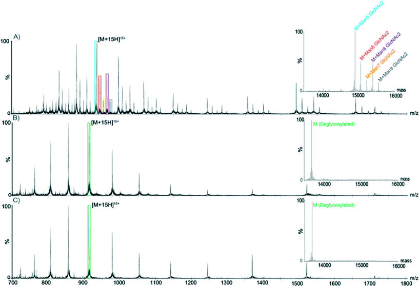
Positive ion-electrospray ionization mass spectra were acquired on a Waters SynaptG2 mass spectrometer (Waters Corporation, Milford, MA, USA) coupled to the HPLC system. Mass spectra were processed using the MassLynx software (Waters Corp, Milford, MA). The activity of PNGase F was assessed by comparing the intensity of RNase peaks ([M + 15H]15+ for glycosylated and deglycosylated species) from a non-deglycosylated sample as well as for samples subjected to off-line and on-chip deglycosylation with PNGase F.
Microreactors were stored 3–13 days in DDW (4 °C) to assess the impact of storage time on performance. The fluorescence intensity of resorufin obtained before and after storage was compared. The ability of the microreactors to be re-used was also evaluated. Microreactors were thoroughly washed (0.05% Tween 20 in DDW) to remove all the fluorescence products between each successive use and re-used up to 5 times at 3 day intervals.
The immobilization and enzymatic reaction schemes performed on the monoliths are summarized in Table 3.
| Step | Reagents | Conditions | Outcome |
|---|---|---|---|
| Immobilization via TE click chemistry and ASA linkage | |||
| Photografting | 200 μL 2-(Boc amino)ethandiol + 0.5% v/v TPO-L | UV exposure, 30 s | The monolith features t-Boc protected amino groups |
| Flushing | 0.05% Tween 20 in DDW | 5 min, 50 μL min−1 | Removal of unreacted products |
| Deprotection | 4 M HCl | 12 h, 4 μL min−1 | Removal of t-Boc protecting group to reveal amino groups at the monolith surface |
| Incubation | 1% w/v ASA in MeOH | 30 min | Coupling of ASA to amino groups on the monoliths |
| Flushing | DDW | 5 min, 30 μL min−1 | Removal of unreacted products |
| Incubation | Galactose oxidase/PNGase F | Overnight, 4 °C | Coupling between immobilized ASA and the free primary amino groups of the enzymes |
| Flushing | DDW | 5 min, 30 μL min−1 | Removal of unreacted groups |
| Immobilization via free thiols (galactose oxidase microreactor) | |||
| Incubation | Galactose oxidase (0.14 mg ml−1, 50 U mL−1) in 50 mM Tris-HCl buffer, pH 8.0 | Overnight, 4 °C | Reversible covalent linkage between cysteine groups on the enzyme and free thiols on the monolith |
| Reduction of disulfide bonds (galactose oxidase microreactor) | |||
| Flushing | 2 mM TCEP | 1 h, 50 μL min−1 | Removal of enzymes immobilized via the formation of disulfide bonds |
| D-Galactose assay (galactose oxidase microreactor) | |||
| Incubation | 50 μM D-galactose, 25 μM ADHP, 0.01 U ml−1 HRP in Tris-HCl buffer (pH 8.0) | 30 min, 37 °C | Oxidation of D-galactose and production of H2O2. Oxidation of ADHP into fluorescent resorufin |
| Deglycosylation of RNase B (PNGase F microreactor) | |||
| Conditioning | 50 mM ammonium bicarbonate buffer | 5 min, 30 μL min−1 | Monolith conditioning |
| Deglycosylation | Ribonuclease B (1 mg ml−1 in 50 mM ammonium bicarbonate buffer) with 5 mM TCEP-HCl heated to 100 °C for 10 min | Gentle suction applied | Collection of the deglycosylated products |
Results and discussion
Monolith characterization
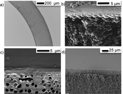
As shown in Fig. 5a), the methanol/TE emulsions filled the channel completely and uniformly and the TE beads fused with the microchannel walls (Fig. 5b)), providing strong anchoring of the monolith. At the interface between the monolith and the TE microchannel walls, a smooth TE film resulting from the fusing of the beads with the wall can be observed (Fig. 5c)). This fusing of the monolith beads with the surrounding TE chip walls was independent of the stoichiometric composition of either the TE monolith, or the TE chip. Therefore, TE monoliths can be covalently anchored to TE microchannel walls without any prior surface activation, independently of which stoichiometric composition is used. Finally, Fig. 5d) shows that the TE monoliths did exhibit shrinkage upon drying, causing cracks and detachment from the channel walls. All monoliths should therefore be filled with DDW and sealed to prevent drying if not used immediately.
Size distribution of bead-liked TE monoliths. Bead uniformity and monodispersity are highly desirable for chromatographic applications. Liu et al. recently demonstrated that enhancing the uniform structure, rather than increasing surface area, could improve chromatographic separation for small molecules on TY globular agglomerates.42Fig. 6 shows a typical size distribution observed for synthesized S-TE monolith beads. The beads are highly regular with a relatively narrow particle size distribution. However, as previously shown in Fig. 4, the size of the beads as well as their packing density was highly dependent on the preparation conditions. Changing the beaker shape, stir bar size or mixing speed can all have an impact on the bead size produced, with a more vigorous stirring resulting in smaller beads. Table 4 shows the average particle size measured for five different S-TE monoliths prepared under similar conditions. Although the distributions are narrow, the means of the 5 populations are statistically different, highlighting the sensitivity of the process.
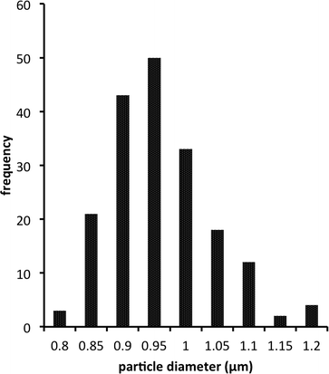 | ||
| Fig. 6 Typical bead size distribution for a bead-like S-TE monolith prepared using 80% w/w methanol as the porogen. | ||
Specific surface area of bead-like TE monoliths. The specific surface area of the monoliths prepared with 80% and 60% methanol were 2.1 ± 0.6 m2 g−1 and 1.8 ± 0.6 m2 g−1, respectively. The small surface area indicates that the material was macroporous, with no or little micro- or mesopores.41 However, since the monoliths were cured in bulk rather than inside a TE microchannel and that they exhibit considerable shrinkage upon drying, the results obtained by Kr BET analysis are not an exact representation of the surface area of the monoliths prepared in much smaller quantities inside TE microfluidic channels. Still, the results are consistent with those obtained by Liu et al.41 for similar organic–inorganic hybrid TE monoliths used successfully in capillary based liquid chromatography.
Galactose assay using the galactose oxidase enzymatic microreactor. Galactose oxidase was immobilized on OSTE-allyl monoliths (40% excess ene) via TE click chemistry and ASA linkage. Additionally, the enzyme was incubated on unmodified OSTE-thiol, OSTE-allyl and S-TE monoliths to promote immobilization via disulfide bridges and to measure the magnitude of adsorption and non-specific interactions between the enzyme and the various TE monoliths. The term “unmodified” is used to describe monoliths without any prior surface treatment or modification, where a simple incubation was used to immobilize the enzyme of interest. As shown in Fig. S1,† the microreactors featuring enzymes immobilized via click chemistry and ASA linkage were significantly more efficient at converting the non-fluorescent ADHP into the fluorescent resorufin product then the unmodified TE microreactors. However, more in-depth investigations are necessary to determine whether the higher efficiency is due to a higher activity or a higher immobilization density of the ASA-immobilized enzyme on the monolith.
The presence of immobilized galactose oxidase on the unmodified TE monoliths is likely due to the formation of disulfide bonds between the free thiol groups present on the galactose oxidase cysteine side-chain and the thiol groups present at the surface of the TE monolith. Similarly, the irreversible adsorption of proteins (trypsin, cytochrome c, lysozyme, myoglobin and β-lactoglobulin) on thiol-functionalized SBA-15 molecular sieves has been reported previously by Yu et al.49,50 The assay results reported in Fig. S1† indicate that a significant amount of enzyme was immobilized at the surface of OSTE-thiol and S-TE monoliths, but also to a smaller extent at the surface of OSTE-allyl monoliths. These results indicate the likely presence of free unconverted thiol groups on S-TE and OSTE-allyl monoliths. Ellman's reagent (DTNB) was used to evaluate the thiol group density at the surface of TE substrates with various stoichiometric compositions. As seen in Fig. S2,† a significant number of free thiol groups are indeed present at the surface of S-TE polymers and even on OSTE-allyl polymers. Typically, in stoichiometric formulations it is expected that the thiol and ene components of the mixture will be consumed at identical rates. However, it is unlikely that monomer conversion is 100%, so some leftover functional groups are expected at the surface of the monoliths. Additionally, homopolymerization of the ene monomers can alter the polymerization stoichiometry, leading to a higher conversion of the ene functional groups compared to the thiol functional groups.51 Cramer et al.51 have demonstrated that the conversion of the ene functional groups can be as much as 15% greater than that of the thiol functional group for the triallyl and tetrathiol monomers used here. These conversion results are consistent with the assay results reported in Fig. S1.†
Reduction of disulfide bonds for enzyme removal TE monoliths. Enzymes that were immobilized on the support only via a disulfide bond can be eluted from the monolith by incubation with TCEP, a reducing agent typically used to break disulfide bonds. After thorough flushing of the reactors with TCEP, most enzymes had been removed from the unmodified TE monoliths, with a conversion of ADHP into the fluorescent resorufin product down by 75–81%. In contrast, the OSTE-allyl monoliths in which the enzymes had been immobilized via click chemistry and ASA linkage could not be regenerated via reduction with TCEP. A fluorescence intensity of 81% of the original value could still be obtained for the conversion of ADHP into the fluorescent resorufin after thorough flushing with TCEP. Therefore, the ASA linkage provides a strong, irreversible covalent immobilization of the enzyme while immobilization via disulfide bonds on unmodified TE monoliths featuring free thiol groups allows for easy regeneration of the monoliths.
Storage stability of the galactose-oxidase enzymatic microreactor. Although enzymatic reactors featuring galactose oxidase immobilized via click chemistry and ASA linkage could be re-used immediately with minimal decrease in activity, even after thorough flushing with TCEP, enzyme activity decreased significantly during storage as shown in Fig. S3.† Similar trends were observed both for never-used and re-used enzymatic microreactors after up to 13 days of storage in DDW at 4 °C. Results indicate that optimally, the microreactors should be used within 4 days of their preparation. However, optimization of the storage conditions could improve the microreactor stability over time.
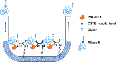
Deglycosylation of RNase B using the PNGase F enzymatic microreactor. PNGase F is a deglycosylation enzyme, which cleaves N-linked carbohydrates. The activity of immobilized PNGase F was assessed using RNase B as a substrate. RNase B contains a single N-linked glycan at residue 60 and MS analysis of a reference sample of native glycosylated RNAse B showed the presence of five high-mannose RNase B glycoforms (with a structure of two N-acetylglucosamines- and five to nine mannose monosaccharides). MS analysis of a reference sample of RNase B deglycosylated off-chip showed a single mass at 13
![[thin space (1/6-em)]](https://www.rsc.org/images/entities/char_2009.gif) 692 Da, corresponding to the fully deglycosylated form of the protein. As shown in Fig. 7, RNase B samples processed with PNGase F both on- and off-chip yielded similar spectra, corresponding to the fully deglycosylated protein and the absence of any of the native glycoforms. Furthermore, similar on-chip deglycosylation was observed for chips employing either strategy for PNGase F immobilization.
692 Da, corresponding to the fully deglycosylated form of the protein. As shown in Fig. 7, RNase B samples processed with PNGase F both on- and off-chip yielded similar spectra, corresponding to the fully deglycosylated protein and the absence of any of the native glycoforms. Furthermore, similar on-chip deglycosylation was observed for chips employing either strategy for PNGase F immobilization.
Conclusions
Thiol–ene microfluidic platforms featuring emulsion-templated porous monoliths show promise for applications such as enzyme microreactors, where a large surface area is necessary and it is paramount that the enzyme is strongly bound to the solid support. Highly uniform and monodisperse bead-like thiol–ene monoliths were prepared inside microfluidic channels. Curing and anchoring inside the microchannel was achieved in a single, rapid photoinitiated step without any prior surface modification. We have shown that immobilization of enzymes on the prepared monoliths via the formation of disulfides is straightforward and reversible. Alternatively, enzymes can be covalently and irreversibly immobilized via the free amino groups in their primary structure by means of ASA linkage. The prepared galactose oxidase and PNGase F microreactors demonstrated good enzymatic activity in a galactose assay and the deglycosilation of RNase B, respectively. The prepared monoliths also offer promise as stationary phases for on-chip separations thanks to their narrow size distribution and the possibility to easily modify their surfaces with chemical groups for various retention modes.Acknowledgements
Funding for this project was provided by the Danish Council for Independent Research – Technology and Production (grant no DFF- 4005-00341). Author S.S. acknowledges funding from Denmark's Advanced Technology Foundation (grant no 144-2013-6). Authors J.N. and G.N. gratefully acknowledge funding by the Erasmus program. Author J.N. acknowledges funding by the Grant Office project (GROFF, CZ.1.07/2.4.00/17.0106) and the Grant Agency of the Czech Republic (project P20612G014). Author K.D.R. acknowledge funding from the Marie Curie Actions Programme of the EU (grant no. PCIG09-GA-2011-294214) and the Danish Council for Independent Research – Natural Sciences (Steno Fellowship no. 11-104058). We acknowledge the Core Facility for Integrated Microscopy, Faculty of Health and Medical Sciences, University of Copenhagen as well as Dorthe Orbæk from the Department of Pharmacy (University of Copenhagen) for her help with SEM imaging. Finally we would like to thank Denis Okhrimenko from the NanoGeoscience Center (University of Copenhagen) for performing the surface area analyses.References
- J. Krenkova and F. Foret, Electrophoresis, 2004, 25, 3550–3563 CrossRef CAS PubMed.
- F. Svec, Electrophoresis, 2006, 27, 947–961 CrossRef CAS PubMed.
- J. Krenkova and F. Svec, J. Sep. Sci., 2009, 32(5–6), 706–718 CAS.
- F. Svec and A. A. Kurganov, J. Chromatogr. A, 2008, 1184, 281–295 CrossRef CAS PubMed.
- J. Krenkova, F. Foret and F. Svec, J. Sep. Sci., 2012, 35, 1266–1283 CrossRef CAS PubMed.
- F. Svec, J. Chromatogr., B, 2006, 841, 52–64 CrossRef CAS PubMed.
- S. Xie, R. W. Allington, J. M. J. Fréchet and F. Svec, Adv. Biochem. Eng./Biotechnol., 2002, 76, 87–125 CrossRef CAS.
- H. Zhang and A. I. Cooper, Soft Matter, 2005, 1, 107 RSC.
- M. S. Silverstein, Polymer, 2014, 55, 304–320 CrossRef CAS PubMed.
- C. Harrison, J. T. Cabral, C. M. Stafford, A. Karim and E. J. Amis, J. Micromech. Microeng., 2004, 14, 153–158 CrossRef.
- P. Wägli, A. Homsy and N. F. de Rooij, Sens. Actuators, B, 2011, 156, 994–1001 CrossRef PubMed.
- L.-H. Hung, R. Lin and A. P. Lee, Lab Chip, 2008, 8, 983 RSC.
- B. Levaché, A. Azioune, M. Bourrel, V. Studer and D. Bartolo, Lab Chip, 2012, 12, 3028–3031 RSC.
- S. H. Kim, Y. Yang, M. Kim, S.-W. Nam, K.-M. Lee, N. Y. Lee, Y. S. Kim and S. Park, Adv. Funct. Mater., 2007, 17, 3493–3498 CrossRef CAS PubMed.
- E. P. Dupont, R. Luisier and M. A. M. Gijs, Microelectron. Eng., 2010, 87, 1253–1255 CrossRef CAS PubMed.
- S. Silvestrini, D. Ferraro, T. Tóth, M. Pierno, T. Carofiglio, G. Mistura and M. Maggini, Lab Chip, 2012, 4041–4043 RSC.
- B. T. Good, S. Reddy, R. H. Davis and C. N. Bowman, Sens. Actuators, B, 2007, 120, 473–480 CrossRef CAS PubMed.
- V. S. Khire, Y. Yi, N. A. Clark and C. N. Bowman, Adv. Mater., 2008, 20, 3308–3313 CrossRef CAS PubMed.
- C. F. Carlborg, T. Haraldsson, K. Öberg, M. Malkoch and W. van der Wijngaart, Lab Chip, 2011, 11, 3136–3147 RSC.
- J. P. Lafleur, R. Kwapiszewski, T. G. Jensen and J. P. Kutter, Analyst, 2013, 138, 845–849 RSC.
- N. A. Feidenhans'l, J. P. Lafleur, T. G. Jensen and J. P. Kutter, Electrophoresis, 2014, 35, 282–288 CrossRef PubMed.
- F. Saharil, C. F. Carlborg, T. Haraldsson and W. van der Wijngaart, Lab Chip, 2012, 12, 3032 RSC.
- T. M. Sikanen, J. P. Lafleur, M.-E. Moilanen, G. Zhuang, T. G. Jensen and J. P. Kutter, J. Micromech. Microeng., 2013, 23, 037002 CrossRef.
- C. E. Hoyle and C. N. Bowman, Angew. Chem., Int. Ed., 2010, 49, 1540–1573 CrossRef CAS PubMed.
- A. B. Lowe, Polym. Chem., 2010, 1, 17 RSC.
- A. B. Lowe, C. E. Hoyle and C. N. Bowman, J. Mater. Chem., 2010, 20, 4745–4750 RSC.
- P. Thirumurugan, D. Matosiuk and K. Jozwiak, Chem. Rev., 2013, 113(7), 4905–4979 CrossRef CAS PubMed.
- Y.-X. Chen, G. Triola and H. Waldmann, Acc. Chem. Res., 2011, 44, 762–773 CrossRef CAS PubMed.
- P. Jonkheijm, D. Weinrich, M. Köhn, H. Engelkamp, P. C. M. Christianen, J. Kuhlmann, J. C. Maan, D. Nüsse, H. Schroeder, R. Wacker, R. Breinbauer, C. M. Niemeyer and H. Waldmann, Angew. Chem., 2008, 120, 4421–4424 CrossRef PubMed.
- V. Grazú, O. Abian, C. Mateo, F. Batista-Viera, R. Fernández-Lafuente and J. M. Guisán, Biotechnol. Bioeng., 2005, 90, 597–605 CrossRef PubMed.
- Y.-H. Rogers, P. Jiang-Baucom, Z.-J. Huang, V. Bogdanov, S. Anderson and M. T. Boyce-Jacino, Anal. Biochem., 1999, 266, 23–30 CrossRef CAS PubMed.
- M. T. Neves-Petersen, T. Snabe, S. Klitgaard, M. Duroux and S. B. Petersen, Protein Sci., 2006, 15, 343–351 CrossRef CAS PubMed.
- W. W. Cleland, Biochemistry (Moscow), 1964, 3, 480–482 CrossRef CAS.
- E. Lovelady, S. D. Kimmins, J. Wu and N. R. Cameron, Polym. Chem., 2011, 2, 559–562 RSC.
- S. Caldwell, D. W. Johnson, M. P. Didsbury, B. A. Murray, J. J. Wu, S. A. Przyborski and N. R. Cameron, Soft Matter, 2012, 8, 10344 RSC.
- B. Sergent, M. Birot and H. Deleuze, React. Funct. Polym., 2012, 72, 962–966 CrossRef CAS PubMed.
- L. Kircher, P. Theato and N. R. Cameron, Polymer, 2013, 54, 1755–1761 CrossRef CAS PubMed.
- C. R. Langford, D. W. Johnson and N. R. Cameron, Polym. Chem., 2014, 5, 6200–6206 RSC.
- X. Gong, W. Wen and P. Sheng, Langmuir, 2009, 25, 7072–7077 CrossRef CAS PubMed.
- R. A. Prasath, M. T. Gokmen, P. Espeel and F. E. D. Prez, Polym. Chem., 2010, 1, 685–692 RSC.
- Z. Liu, J. Ou, H. Lin, Z. Liu, H. Wang, J. Dong and H. Zou, Chem. Commun., 2014, 50, 9288–9290 RSC.
- Z. Liu, J. Ou, H. Lin, H. Wang, Z. Liu, J. Dong and H. Zou, Anal. Chem., 2014, 86, 12334–12340 CrossRef CAS PubMed.
- S. Brunauer, P. H. Emmett and E. Teller, J. Am. Chem. Soc., 1938, 60, 309–319 CrossRef CAS.
- G. L. Ellman, Arch. Biochem. Biophys., 1959, 82, 70–77 CrossRef CAS.
- P. W. Riddles, R. L. Blakeley and B. Zerner, in Enzyme Structure Part I, Academic Press, 1983, vol. 91, pp. 49–60 Search PubMed.
- A. J. D. Magenau, J. W. Chan, C. E. Hoyle and R. F. Storey, Polym. Chem., 2010, 1, 831 RSC.
- A. Patton and P. Chism, Anal. Chem., 1951, 23, 1683–1685 CrossRef CAS.
- J. Tiller, P. Berlin and D. Klemm, Biotechnol. Appl. Biochem., 1999, 30, 155–162 CAS.
- H. H. P. Yiu, C. H. Botting, N. P. Botting and P. A. Wright, Phys. Chem. Chem. Phys., 2001, 3, 2983–2985 RSC.
- H. H. P. Yiu, P. A. Wright and N. P. Botting, J. Mol. Catal. B: Enzym., 2001, 15, 81–92 CrossRef CAS.
- N. B. Cramer and C. N. Bowman, J. Polym. Sci., Part A: Polym. Chem., 2001, 39, 3311–3319 CrossRef CAS PubMed.
Footnote |
| † Electronic supplementary information (ESI) available. See DOI: 10.1039/c5lc00224a |
| This journal is © The Royal Society of Chemistry 2015 |


