Rapid modulation of droplet composition with pincer microvalves
Christopher J.
Ochs
and
Adam R.
Abate
*
Department of Bioengineering and Therapeutic Sciences, California Institute for Quantitative Biosciences, University of California San Francisco, San Francisco, California, USA. E-mail: adam.abate@ucsf.edu
First published on 3rd November 2014
Abstract
Single-layer membrane valves are simple to fabricate and to integrate into microfluidic devices. However, due to their rectangular flow channel geometry, they do not fully seal. Here, we show that liquid flow can be reduced by over 3 orders of magnitude, enabling the contents of forming droplets to be dynamically modulated. We use this precision control to perform combinatorial DNA synthesis in the droplets.
Microfluidic valves have enabled disruptive technologies in gene sequencing, single cell analysis, and structural and synthetic biology.1–5 Numerous techniques have been developed to pump, switch, and isolate fluids in microfluidic channel networks via on-chip or off-chip control, including solenoids,6 various types of injectors,7–9 metal screws and pin-valves,6,10 as well as single-layer11–13 and multilayer membrane valves.14 Amongst these, multilayer membrane valves (MLMV) are the method of choice when rapid and complete sealing of channels is necessary. These valves utilize a rounded geometry and vertical deflection of an elastic membrane to completely seal channels and achieve reliable, repeatable on–off actuation. However, fabricating microfluidic devices with these valves requires specialized photoresists and a mask aligner. Moreover, minor errors in fabrication or alignment of control and flow layers can significantly impact valve performance.15
Single-layer membrane valves (SLMV) integrate the control and fluidic channels into a single layer, allowing both networks to be fabricated simultaneously and obviating the need for specialized photoresists or alignment. In these valves, pressurized control channels deflect the elastic side wall of the flow channel, enabling modulation of the flow rate.12 However, because the flow channels are rectangular in shape, small “gutters” remain open at the corners of the channels even when the valve is fully actuated, causing leaky flow. As a result, these valves have been primarily relegated to use as sieve valves for high throughput particle and cell sorting.11,13,16 If leakiness could be reduced with appropriate changes to design, single-layer valves would be valuable for applications prioritizing both control and simplicity.
In this paper, we characterize the leakiness of SLMVs and demonstrate that with appropriate design, leaky flow can be made negligible for most applications of biological relevance. As an example of their utility, we use them to modulate the concentrations of DNA oligos in droplets by over three orders of magnitude, sufficient to reliably control the sequences of the constructs assembled in each droplet. In addition, we demonstrate the use of these valves to generate a library of droplets labelled with controlled combinations of dyes, a critical first step in the creation of spectrally-encoded particles.17
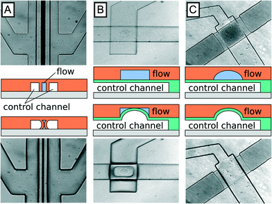
Membrane valves utilize a pressurized chamber to deflect the flexible wall of a flow channel, increasing flow channel hydrodynamic resistance and thereby enabling regulation of flow rate. Three membrane valve types have been developed for lab-on-a-chip applications. Amongst these, SLMV are the simplest to design and to fabricate, but exhibit leaky gutter flow (Fig. 1A), similar to the more complex MLMV based on rectangular channel geometries (Fig. 1B). In both examples, gutter flow results from the use of rectangular channels that do not completely seal in the off state. To completely seal the channels, a rounded geometry can be implemented that prevents the formation of open gutters in the off state, as illustrated in Fig. 1C. MLMV with rounded channels thus afford the best performance of the three valve types but are also the hardest to fabricate, requiring both specialized photoresists to generate rounded channels and precision alignment of flow and control layers.
When deciding which type of valve to integrate into a microfluidic system, it is important to consider trade-offs between simplicity, performance, and robustness. Of the three valve types, SLMV are the simplest, because they can be fabricated in the same layer as the flow channel, obviating the need for alignment, an error prone step in the fabrication process. Furthermore, complete sealing of the flow channel is not essential for many applications. Rather, a marked change in flow rate between on and off states is sufficient, making the simplicity of single layer valves a major advantage.
To investigate single-layer valve performance, we estimate the flow rates anticipated in the on and off states. For a constant pressure drop across a rectangular channel, the flow rate Q is inversely proportional to the hydrodynamic resistance Rh, following Qrect. ~ 1/Rh = wh3/12μL for w ≫ h, where L is the channel length, w the channel width, and h the channel height.18 In the actuated state, flow is restricted to the gutters, which we approximate as two narrow cylinders where Qgutter ~ πr4/8μL. Based on optimised dimensions from our previous paper (w = 30 μm, h = 90 μm, and L = 1000 μm),12 the flow rate is reduced ~1300× by decreasing the channel cross sectional area to ~10% its value in the open state. Actuating the valves further to reduce cross sectional area to ~4% reduces the flow rate ~8000×. When forming droplets from streams controlled by valves, the relative concentrations of reagents loaded into the droplets is equal to the relative flow rates of the reagents; a flow rate reduction of 8000× thus results in a concentration change by the same amount. This dynamic range is sufficient to control most biological reactions.
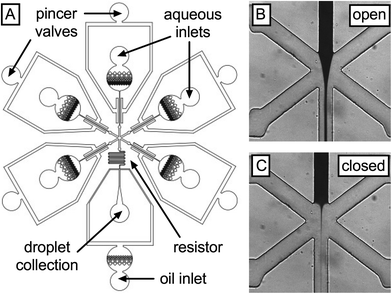
To empirically confirm the performance of the single-layer valves, we create a device that allows modulation of the flow rates of five liquids injected into a droplet generator (Fig. 2A). The five liquids are pressurized to the same values and injected into the inlet ports of the microfluidic device; since the inlet channels of each liquid are identical, their flow rates into the droplet generator are equal unless the valves are actuated. The valves consist of a symmetric pincer geometry deflecting ~15 μm membranes into their respective fluidic channels using pressures ranging from 0 to 67 psi. To facilitate membrane deflection, all devices are fabricated from “soft” PDMS (6% cross linker) and sealed at the bottom with a flexible PDMS layer on glass. To enable visualization of leaky flow, we dye one of the aqueous solutions with 2 mg mL−1 IR dye 783 (central inlet) and inject water into the other inlets (Fig. 2B). By measuring the area accommodated by the dye downstream of the intersection of the five inlets, we estimate the flow rate of this liquid and observe how it changes with actuation of the valve on the central channel before and after full valve actuation (Fig. 2B and C, respectively).
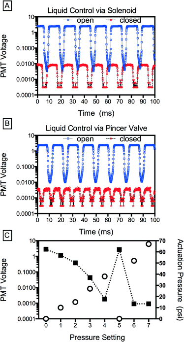
The IR dye allows us to qualitatively assess valve performance, but to quantify leakage as a function of valve actuation, we replace this dye with a fluorescent dye (100 μM fluorescein in PBS), injecting buffer (PBS) into the other inlets; consequently, the droplets generated contain a volume of fluorescent dye proportional to the flow rate of the central inlet. By sensitively measuring dye concentration using a photomultiplier tube, we can accurately detect even minute valve leakiness. To generate droplets with the device, we pressurize the aqueous solutions with a custom manifold (12.7 psi) and supply fluorinated oil containing 2 wt% of a biocompatible surfactant (RAN Technologies) at 600 μL h−1 using a syringe pump. We also compare the pincer valves to commercially available off-chip solenoid valves (Western Analytical Products). When the central solenoid is closed, shutting off the dye flow, fluorescence reduces ~300× but it does not go to zero (Fig. 3A). This implies that, even when the solenoid is closed, a small flow rate remains. This could be due to leakage through the solenoid mechanism or, alternatively, the relatively large capacitance of the dead volume connecting the solenoid to the microfluidic device, which remains pressurized even after valve closure and may continue to pump dye solution into the droplet generator. Consequently, as is well known when using off-chip valves, it is often not possible to completely stop flow on a reasonable experimental time scale (minutes). By contrast, the pincer valves achieve an instantaneous reduction in droplet fluorescence of >3000×, significantly outperforming the solenoid valve; this corresponds to an estimated 94% constriction in cross-sectional area of the channel with actuation.
Pincer valves are analogue: the degree of deflection of the membrane and the change in flow rate in the channel are proportional to the pressure applied to the valve; this allows not only on-off control but continuous modulation of the flow rate (Fig. 3C). An additional advantage of the pincer valves is that the volume displaced by the valve membrane under actuation is small, so that a relatively small flux is required to equilibrate the pressure downstream of the valve; this allows rapid modulation of the flow rate, as illustrated by the reversibility of flow to actuation in points 4, 5, and 6 in Fig. 3C.
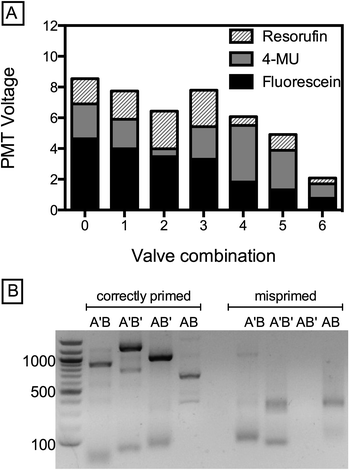
The ability to generate droplets with defined concentrations of reagents over a large dynamic range is valuable for numerous biological applications utilizing microfluidic droplets. For example, by loading different solutions into the five inlets and controllably modulating the relative ratios of the solutions, it is possible to scan large concentration spaces quickly. A potential application of this is the optimization of metabolic pathways or gene circuits requiring precise combinations of inducers, cofactors, DNA constructs, and other components.19,20 To illustrate the power of this method for creating droplets with controlled combinations of reagents, we introduce three dye solutions (fluorescein, resorufin, 5-methylumbelliferone (5-MU) and 2 PBS reservoirs) into the device and modulate their relative concentrations using the valves. The amount of a particular reagent in the droplet is proportional to its flow rate and inversely proportional to actuation pressure, allowing us to generate droplets of different, defined types, as shown by the combinations plotted (Fig. 4A).
Generating combinatorial droplet libraries is useful for a broad array of biological applications, including spectral encoding of beads and performing biological screens.17,20 Another example is the synthesis of defined DNA constructs. The ability to modulate a DNA oligo's concentration by 3000× is sufficient to determine whether or not it will integrate into the construct created by Golden Gate Assembly (GGA). Indeed, if the ratio between two compatible DNA fragments A and B is offset by just 10×, ligation efficiency decreases significantly and DNA assembly fails.21 To demonstrate the utility of pincer valves for this application, we perform combinatorial DNA assembly using two GGA-compatible DNA fragments of type A (A = 250 bp, A′ = 500 bp), which are exclusively compatible with two fragments of type B (B = 350 bp or B′ = 700 bp). We PCR-amplify the fragments from a lambda phage genome to introduce GGA-specific 4 bp overhangs, and introduce each fragment through an individual channel with the central channel supplying enzymes and reaction buffer (BsaI and T4 ligase). By opening or closing the respective valves, we emulsify the four possible assembly products (A′B, A′B′, AB′, AB), collected into separate tubes. After thermocycling off-chip, we extract the constructs by breaking the emulsions and PCR-amplify with matching primers for agarose gel analysis; for example A′B is amplified using Arev and B′rev. All correct assembly products are amplified, resulting in product bands at the expected positions of A′B = 850 bp, A′B′ = 1200 bp, AB′ = 950 bp and AB = 600 bp, as shown in Fig. 4B. As expected, neither the control PCR reactions (wrong primers for respective construct, Fig. 4B, far right) nor a control emulsion of AA′ yield product. Evidently, the small leakage does not impact successful ligation of the desired product, demonstrating the potential of pincer valves for synthetic biology applications like construct assembly and combinatorial gene library synthesis.
Materials and methods
Unless otherwise indicated, chemicals were purchased from Sigma-Aldrich (St. Louis, MO, USA). The microfluidic devices are fabricated using standard photolithography.22 PDMS replicas are cast by pouring PDMS at 16![[thin space (1/6-em)]](https://www.rsc.org/images/entities/char_2009.gif) :
:![[thin space (1/6-em)]](https://www.rsc.org/images/entities/char_2009.gif) 1 ratio of base
1 ratio of base![[thin space (1/6-em)]](https://www.rsc.org/images/entities/char_2009.gif) :
:![[thin space (1/6-em)]](https://www.rsc.org/images/entities/char_2009.gif) curing agent (Sylgard 184, Dow Chemical, MI, USA) and baked at 80 °C for 1 hour. Fabricated channel width are as follows: resistor (20 μm), flow channels in valve area (30 μm), regular flow channels (60 μm), droplet generator nozzle (20 × 40 μm), PDMS membranes (20 μm). After peeling the replicas from the wafer master, we punch access holes with a 0.75 mm biopsy punch and bond PDMS-coated glass slides (10 μm) to the bottom of the devices using oxygen plasma treatment. All devices are treated with Aquapel (PPG Industries) to reduce wetting during droplet generation and dried for 1 hour at 80 °C prior to use. We use HFE-7500 fluorinated oil with 2 wt% triblock surfactant (RainDance Technologies) for all experiments at a flowrate of 600 μL per hour. Pincer valves are operated between 0–67 psi using T900X Electric-Pneumatic transducers (ControlAir Inc). To avoid bleed over between detection channels, we detect droplet fluorescence using offset laser spots (405, 473, 532 nm excitation wavelength) and analyse the data using custom LabView software.
curing agent (Sylgard 184, Dow Chemical, MI, USA) and baked at 80 °C for 1 hour. Fabricated channel width are as follows: resistor (20 μm), flow channels in valve area (30 μm), regular flow channels (60 μm), droplet generator nozzle (20 × 40 μm), PDMS membranes (20 μm). After peeling the replicas from the wafer master, we punch access holes with a 0.75 mm biopsy punch and bond PDMS-coated glass slides (10 μm) to the bottom of the devices using oxygen plasma treatment. All devices are treated with Aquapel (PPG Industries) to reduce wetting during droplet generation and dried for 1 hour at 80 °C prior to use. We use HFE-7500 fluorinated oil with 2 wt% triblock surfactant (RainDance Technologies) for all experiments at a flowrate of 600 μL per hour. Pincer valves are operated between 0–67 psi using T900X Electric-Pneumatic transducers (ControlAir Inc). To avoid bleed over between detection channels, we detect droplet fluorescence using offset laser spots (405, 473, 532 nm excitation wavelength) and analyse the data using custom LabView software.
The sequences of the primers used to amplify Golden Gate compatible DNA fragments from lambda phage genome are as follows: A (250 mer) forward: ACG TTG GTC TCA GCT TCG TTC CGT GCT GTC C; A (250 mer) reverse: GAT ATC TTT AAT GTG GGG CTG GTT GCC TCC T; A′ (500 mer) forward: GGT ATG GTC TCA GCT TCG GCC CTT GTG ACT G; A′ (500 mer) reverse: GGA ATT GAG GCC GTC CCC GTT GAC GCA CTC C; B (350 mer) forward: TTA GTG GTC TCA AAG CGC AGC TTG GCC TGA A; B (350 mer) reverse: GTT AAT TTC CCT TGC AGC GCT GGG CTT TGT A; B′ (700 mer) forward: GGC TCG GTC TC AAA GCT CGG CGT CAC AGG TT; B′ (700 mer) reverse: GTA TAC CAG GTG TCC TCC ACG CAT CCA GCT C. For Golden Gate assembly (GGA), a 15 μL reaction is set up by combining equimolar amounts of DNA fragment A and B (~100 ng), 1.5 μL 10× NEB T4 Buffer, 1.5 μL 10× BSA, 1 μL BsaI, and 1 μL T4 ligase at 2 million units mL−1 (New England Biolabs).21 For each reaction, we collect 50 μL of emulsion, remove the fluorinated oil (HFE-7500, 3M Novec) using a 1 mL syringe and replace the oil with FC-40 (Sigma-Aldrich) containing 5 wt% surfactant. Reactions are run in a thermocycler at 10 cycles of 2 min/37 °C, 3 min/20 °C, 1 cycle 5 min/50 °C, 5 min/80 °C. After assembly, we add 20 μL perfluoro-1-octanol to break the emulsion and extract the aqueous phase for analysis. Products from the PCR reactions (KAPA Hifi mix, Kapa Biosystems) and Golden Gate Assembly are run on 1.5% agarose gels (1× TE buffer, 150 V, 12 min).
Conclusions
Single-layer pincer valves provide precision control over flow rate and exhibit negligible leakiness in the closed state, allowing modulating of flow rate and droplet concentration over three orders of magnitude. The simplicity of these valves, the ease at which they can be integrated into microfluidic devices, and their reliability, robustness, and performance make them valuable for a range of biological applications, including for generating spectrally-encoded droplets and beads, performing DNA synthesis, and screening large, combinatorial chemical and biological parameter spaces.Acknowledgements
The authors thank Dr. Adam Sciambi for helpful discussions regarding device design and laser detection setup. This work is supported by DARPA grant number 84389.01.44908, an NSF CAREER Award (DBI-1253293), a grant from the NIH (HG007233-01), a New Frontiers Research Award from the UCSF/Sandler Foundation Program for Breakthrough Biomedical Research, and a grant from the University of California Proof of Concept Program.Notes and references
- C. Hansen and S. R. Quake, Curr. Opin. Struct. Biol., 2003, 13, 538–544 CrossRef CAS PubMed.
- D. B. Weibel and G. M. Whitesides, Curr. Opin. Chem. Biol., 2006, 10, 584–591 CrossRef CAS PubMed.
- P. M. Fordyce, D. Gerber, D. Tran, J. Zheng, H. Li, J. L. DeRisi and S. R. Quake, Nat. Biotechnol., 2010, 28, 970–975 CrossRef CAS PubMed.
- M. S. Ferry, I. A. Razinkov and J. Hasty, in Methods in Enzymology, ed. V. Chris, Academic Press, 2011, vol. 497, pp. 295–372 Search PubMed.
- S. J. Tan, H. Phan, B. M. Gerry, A. Kuhn, L. Z. Hong, Y. Min Ong, P. S. Y. Poon, M. A. Unger, R. C. Jones, S. R. Quake and W. F. Burkholder, PLoS One, 2013, 8, e64084 CAS.
- S. Elizabeth Hulme, S. S. Shevkoplyas and G. M. Whitesides, Lab Chip, 2009, 9, 79–86 RSC.
- A. R. Abate, T. Hung, P. Mary, J. J. Agresti and D. A. Weitz, Proc. Natl. Acad. Sci. U. S. A., 2010, 107, 19163–19166 CrossRef CAS PubMed.
- K. Churski, M. Nowacki, P. M. Korczyk and P. Garstecki, Lab Chip, 2013, 13, 3689–3697 RSC.
- J. Tang, A. M. Jofre, R. B. Kishore, J. E. Reiner, M. E. Greene, G. M. Lowman, J. S. Denker, C. C. C. Willis, K. Helmerson and L. S. Goldner, Anal. Chem., 2009, 81, 8041–8047 CrossRef CAS PubMed.
- M.-E. Brett, S. Zhao, J. Stoia and D. Eddington, Biomed. Microdevices, 2011, 13, 633–639 CrossRef PubMed.
- N. Sundararajan, D. S. Kim and A. A. Berlin, Lab Chip, 2005, 5, 350–354 RSC.
- A. R. Abate and D. A. Weitz, Appl. Phys. Lett., 2008, 92, 243509 CrossRef PubMed.
- H. Kim and J. Kim, Microfluid. Nanofluid., 2014, 16, 623–633 CrossRef CAS.
- M. A. Unger, H.-P. Chou, T. Thorsen, A. Scherer and S. R. Quake, Science, 2000, 288, 113–116 CrossRef CAS.
- P. M. Fordyce, C. A. Diaz-Botia, J. L. DeRisi and R. Gomez-Sjoberg, Lab Chip, 2012, 12, 4287–4295 RSC.
- A. R. Abate, J. J. Agresti and D. A. Weitz, Appl. Phys. Lett., 2010, 96, 203509 CrossRef PubMed.
- R. E. Gerver, R. Gomez-Sjoberg, B. C. Baxter, K. S. Thorn, P. M. Fordyce, C. A. Diaz-Botia, B. A. Helms and J. L. DeRisi, Lab Chip, 2012, 12, 4716–4723 RSC.
- H. Stone, in CMOS Biotechnology, ed. H. Lee, R. Westervelt and D. Ham, Springer, US, 2007, ch. 2, pp. 5–30 Search PubMed.
- M. Quach, N. Brunel and F. d'Alché-Buc, Bioinformatics, 2007, 23, 3209–3216 CrossRef CAS PubMed.
- Y. Dharmadi, A. Murarka and R. Gonzalez, Biotechnol. Bioeng., 2006, 94, 821–829 CrossRef CAS PubMed.
- Z. Z. Sun, E. Yeung, C. A. Hayes, V. Noireaux and R. M. Murray, ACS Synth. Biol., 2013, 3, 387–397 CrossRef PubMed.
- Y. Xia and G. M. Whitesides, Angew. Chem., Int. Ed., 1998, 37, 550–575 CrossRef CAS.
| This journal is © The Royal Society of Chemistry 2015 |


