Carbon nanotube-immobilized super-absorbent membrane for harvesting water from the atmosphere†
Sagar
Roy
,
Chaudhery Mustansar
Hussain
and
Somenath
Mitra
*
Department of Chemistry and Environmental Science, New Jersey Institute of Technology, Newark, New Jersey 07102, USA. E-mail: mitra@njit.edu; Fax: +1 973 596 3586
First published on 4th August 2015
Abstract
This paper describes the development of a carbon nanotube (CNT)-immobilized membrane for harvesting pure water from air. The CNTs were incorporated into a layer of super-absorbing poly(acrylamide-co-acrylic acid) which was cast over a porous hydrophilized polypropylene support. The super-absorbing polymer tended to bind to the water molecules to form water clusters. The incorporation of CNTs led to the interruption of specific water–polymer as well as water–water interactions to generate more free water which permeated more easily through the membrane. The CNTs were functionalized with carboxylic groups to improve the dispersibility into the polymer matrix. The water vapor extraction efficiency reached over 50%, and the presence of CNTs led to an enhancement in water vapor removal by as much as 45% and in the mass transfer coefficient by 44%.
Water impactRecent climatic changes, fairly widespread drought and extensive water use are drawing the world into a state of water scarcity. This forces us to look for engineered water sources by conventional methods such as desalination, and also to look for unconventional sources. On-site water generation by extracting water vapor from air via permeation through a polymeric membrane is an attractive alternative approach for generating pure water. Carbon nanotubes (CNTs) immobilized in a membrane containing a super-absorbent polymer are presented as an effective method to sorb water and then break up water clusters for high permeation flux. Besides addressing the important application of generating drinking water from air, this development opens the door for many other humidity control applications. |
Introduction
The supply of potable water all over the world is a growing challenge. To help alleviate this burden, on-site water treatment methods such as distillation, reverse osmosis (RO) and waste water recycling systems are being developed.1–7 Besides the methods mentioned above, on-site water generation systems that extract water vapor from air have been developed. The removal of water vapor from gaseous streams also has many industrial applications which include dehydration of natural and flue gases, drying of compressed air and storage of fruits and vegetables under protective atmosphere.8,9 In addition, humidity control in closed spaces such as air conditioning in buildings, aviation and space flight is of major importance.10Several approaches for water vapor extraction from air to produce clean water have been studied.11–14 Typical methods of water extraction include cooling and refrigeration, use of liquid and solid desiccants, and compression. However, these conventional techniques possess inherent disadvantages; for example, the condensed water can be contaminated, and desiccant systems involve energy-inefficient regeneration steps and may have to be discarded after several uses.15–17
Selective water vapor transport through polymeric membranes is an attractive approach because it provides continuous operation, has a relatively small footprint, is easy to operate and reduces energy costs.18–21 Membrane-based dehumidification processes have used a wide variety of membranes that include cellulosic polymers, polyamides, polyimides, polyacrylonitrile, polyethylene, polypropylene, polysulfones, and polydimethylsiloxane.8,22–25 However, the overall performance in terms of flux as well as water removal is still relatively poor and such processes are not competitive at this time.23,26,27
The unique sorbent properties of CNTs have been utilized in different membrane separation processes including water treatment.28 CNTs deposited on ceramic matrices via chemical vapor deposition have shown high permeation rates for water29 and theoretical studies have shown that the permeation rates for certain liquids and gases through CNTs surpass those expected from classical diffusion models.30,31 This enhancement has been attributed to the smooth CNT surface, frictionless rapid transport, molecular ordering32 and increase in diffusivity.29,33 CNTs incorporated into polymer matrices have been effectively used in diverse chemical separation processes such as solvent extraction, nanofiltration, pervaporation and membrane distillation.34–37
While CNTs are potentially good sorbents that can allow rapid mass transfer to increase the yield of water during extraction from air, they need to be incorporated into a mechanically stable, highly hydrophilic environment. The introduction of functionalized CNTs into a super-absorbent polymer (SAP) membrane provides the dual benefits of high water sorption along with nano-structured sorption–desorption sites for rapid mass transport.37 In this present study, we demonstrate a highly hydrophilic carbon nanotube-immobilized SAP membrane for generation of water from the atmosphere.
Experimental details
Chemicals and materials
Poly(acrylamide-co-acrylic acid), potassium dichromate (K2Cr2O7), sulphuric acid (95.7% purity, ACS reagent), and acetone (99% purity) were obtained from Sigma-Aldrich (St. Louis, MO). High purity N2 (Airgas, NJ) and deionized water were used in the experiments. Raw multi-walled carbon nanotubes (CNTs) were purchased from Cheap Tubes Inc., Brattleboro, VT. The average diameters of the CNTs were ~30 nm with a length of up to 15 μm.The raw CNTs were functionalized to their carboxylated form in a microwave accelerated reaction system (mode: CEM Mars) using methods published before.38 The CNTs were treated with a mixture of concentrated sulfuric acid and nitric acid solution at 140 °C for 20 min in the microwave to form their carboxylated analogs. These were washed, filtered and dried under vacuum at 80 °C. The CNTs were carboxylated to be more hydrophilic so that they could interact with water vapor and be compatible with the SAP phase.
Membrane modules
The hollow fiber membrane module used in these experiments was prepared within a 30 cm long stainless steel casement with a male tee connector placed at each end of the module. The casement and hollow fiber strands were sealed using a fast drying epoxy resin (Resin Technology Group, LLC, South Easton, MA). The sealed “T” units prevented the intermixing of the lumen and permeated contents. They also served as the inlet/outlet for the sample and the permeate. The effective surface area of the module was calculated to be 94.03 cm2.Fabrication of the carbon nanotube-immobilized membrane (CNIM)
In our study, 0.1 wt% carboxylated CNTs were dispersed in water via sonication for 3 h. The –COOH functional groups provided good dispersibility. The poly(acrylamide-co-acrylic acid) SAP was dissolved separately in water under stirring conditions overnight. This copolymer solution was then added to the CNT dispersion and was mechanically stirred for 3 h. Celgard X-20 PP hollow fibers are highly hydrophobic in nature, and therefore, they were hydrophilized by chromic acid treatment to make a compatible surface and for better adhesion with the SAP film. After hydrophilization, the aqueous solution of SAP-CNT was passed through the bore of the hydrophilized membrane at a low flow rate. The excess solution was removed by flushing with air at a very low flow rate through the module. The module was then placed in an oven at 60 °C overnight for further annealing. The composite membrane structure developed in this research is shown in Fig. 1a.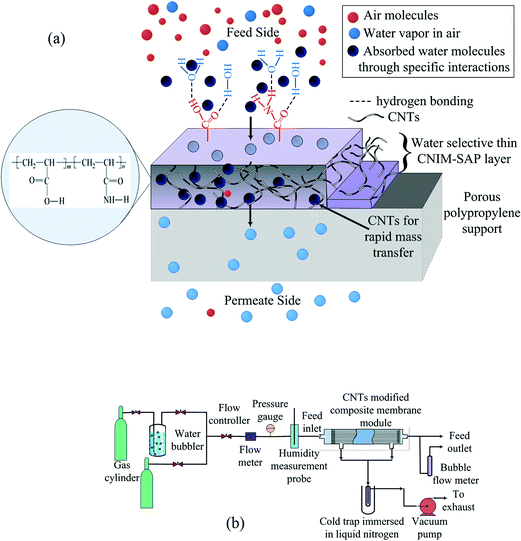 | ||
| Fig. 1 (a) Schematic diagram of the CNIM-SAP membrane and (b) the schematic representation of the experimental system used for water harvesting. | ||
Membrane characterization
The CNIM-SAP membrane was characterized by using scanning electron microscopy (SEM), thermogravimetric analysis (TGA) and differential scanning calorimetry (DSC). Details are presented in the ESI.† Contact angle measurements were performed to study the hydrophilic nature of the CNIM-SAP. These were carried out using a digital video camera mounted at the top of the stage.The sorption isotherms were measured as follows. A flat CNIM-SAP membrane was prepared from its aqueous solution by casting over a Teflon sheet. The dried and pre-weighed membrane was placed in a temperature control box. Water vapor at different concentrations was generated from the water sample and circulated with constant low-flow nitrogen to maintain a particular RH in the system. The weight of the membrane was measured at different time intervals until saturation. Sorption experiments were also conducted at three different temperatures, i.e., 30, 40 and 50 °C.
The schematic representation of water vapor removal from the simulated air stream is shown in Fig. 1b. A N2 gas stream was passed through a water-filled bubbler, and was mixed with another dry N2 gas stream to deliver the water vapor feed with a certain concentration to the module inlet. The flow rates of the N2 streams were adjusted carefully to obtain the desired water vapor concentration. The feed flow rates were varied from 1–5 ml min−1 and the water vapor concentrations were varied between 4000 to 40![[thin space (1/6-em)]](https://www.rsc.org/images/entities/char_2009.gif) 000 ppm. A vacuum pump was connected to the shell-side of the module end through a cold trap immersed in a liquid nitrogen container. The highly hydrophilic membranes allowed only water vapor to pass through the membrane. These water vapors were collected into the cold trap kept in liquid nitrogen. The concentration of water vapor in the feed and collected samples was calculated. Each experiment was repeated at least three times to ensure reproducibility and the average of these data is presented. The relative standard deviation was found to be less than 1%. The error bars represent the variability of one standard deviation.
000 ppm. A vacuum pump was connected to the shell-side of the module end through a cold trap immersed in a liquid nitrogen container. The highly hydrophilic membranes allowed only water vapor to pass through the membrane. These water vapors were collected into the cold trap kept in liquid nitrogen. The concentration of water vapor in the feed and collected samples was calculated. Each experiment was repeated at least three times to ensure reproducibility and the average of these data is presented. The relative standard deviation was found to be less than 1%. The error bars represent the variability of one standard deviation.
Results and discussion
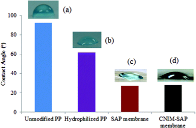
The change in hydrophilicity of the unmodified and modified PP supports is presented in Fig. 2. The contact angle value of the unmodified PP membrane (93 ± 1°) clearly demonstrates the hydrophobic nature of the membrane. After hydrophilization, the contact angle decreased to well below 90° for the modified PP support. The SAP and CNIM-SAP coatings over the modified PP support exhibit a similar type of enhanced hydrophilicity and the contact angle decreased further to 28 ± 2°.Performance of CNIM-SAP
The transport of gas through a dense polymeric membrane is usually governed by the solution diffusion mechanism.39 Here, the gas molecules preferentially sorb onto the membrane surface which is followed by diffusion under a concentration gradient. The rate of transport of the solute across the membrane can be expressed in terms of flux, which can be expressed as:| Jw = k(pw,f − pw,p) | (1) |
 | (2) |
The partitioning of water vapor on the membrane and its desorption on the permeate side may be considered instantaneous and the vapor phase boundary layer on the permeate side may be assumed to offer negligible mass transfer resistance.40 Therefore, the maximum mass transfer resistances are attributed to the boundary layer at the membrane–air interface and diffusion through the membrane. The liquid boundary layer resistance depends upon the feed flow rate, viscosity and diffusivity, whereas the membrane resistance is a function of the membrane thickness, temperature and permeability of a specific compound.40
As the concentration of water vapor in the permeate side is negligible, the overall mass transfer coefficient (k) can be described as:
 | (3) |
The extraction efficiency of the process was quantified based on the removal of water vapor from the air stream and was expressed as percent water vapor removal (% R):
 | (4) |
The rate of water vapor transport across the membrane can be expressed in terms of flux Jw (gm mol cm−2 min−1):
 | (5) |
Fig. 3 shows the specific sorption capacity for water of CNIM-SAP as a function of relative humidity at different temperatures. The presence of a small amount of CNTs did not alter the sorption characteristics of the SAP. From the figure, it is also observed that the increase in temperature did not significantly alter the sorption capacity of the CNIM-SAP. This is an interesting feature because under normal circumstances, the sorption capacity decreases with an increase in temperature,41–43 but that was not observed in the temperature range studied. The ideal and linear sorption behavior as described by Henry's law of adsorption can be altered dramatically by specific interactions with the polymer and among the solute molecules. It is evident from the figure that the sorption isotherms closely resemble Rogers type-III sorption. This type of isotherm is observed when water molecules serve as swelling agents for the polymer, and follows the Flory–Huggins principle where the solubility coefficient increases with pressure.44,45 Here, the mutual interaction of the sorbed water molecules leads to the formation of clusters within the membrane matrix.46
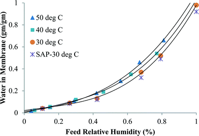 | ||
| Fig. 3 The variation of water sorption in CNIM-SAP at different water vapor concentrations and temperatures. | ||
Water vapor removal was studied as a function of feed concentration at different temperatures and the results are shown in Fig. 4a and b. The water vapor flux and the percent removal increased with relative humidity. This was attributed to the enhanced driving force for mass transfer. In the temperature range studied, the increase in flux and water vapor removal was attributed to the increase in the diffusion coefficient. In a typical solution diffusion model, the permeability is given as a product of solubility in the membrane and the diffusion coefficient. Under normal circumstances, the former is known to decrease with an increase in temperature, but as seen in Fig. 4, that was not the case.47 Therefore, permeation was directly related to the diffusion coefficient. As already mentioned, the sorbed water molecules formed clusters within the membrane matrix and this prevented their rapid permeation. However, in the CNIM-SAP, the transport of water vapor could take place in the CNT domains where the CNTs allow the water vapor molecules to adsorb–desorb easily and migrate to the permeate side. In short, the CNTs can break up the water clusters and facilitate faster water vapor transport. The enhancement in the percentage of water extracted by the CNTs is presented in Fig. 4c. A significant improvement in water vapor removal was observed and the enhancement increased with temperature and was as high as 45%. At high humidity, more water clusters were formed in the SAP and the CNTs were more effective in breaking them up which led to higher enhancements.
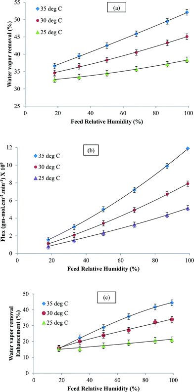 | ||
| Fig. 4 (a) Water vapor removal, (b) water vapor flux and (c) enhancement in water vapor removal (at 1 mL min−1) as a function of the inlet feed concentration. | ||
Fig. 5a shows the water vapor flux as a function of the inlet air flow rate. It was observed that the flux increased with the feed flow rate. However, the percent removal of water vapor reduced with an increase in the flow rate due to shorter residence time (Fig. 5b). It was also observed that at a given flow rate, the flux and percent water removal increased with an increase in temperature. Fig. 5c shows the variation in enhancement in the presence of CNTs at different feed flow rates and temperatures. The CNIM-SAP exhibited higher enhancement at increased temperatures. The increase in the flow rate led to a reduction in boundary layer formation on the membrane surface. Since the CNTs were embedded in the matrix, they did not affect the boundary layer formation. Consequently, the enhancement in water removal in the presence of CNTs was not affected by the feed flow rate.
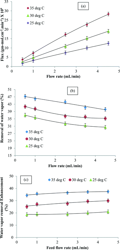 | ||
| Fig. 5 (a) Water vapor flux, (b) water vapor removal and (c) enhancement in water vapor removal (at 68% RH) as a function of the inlet flow rate at different temperatures. | ||
Tables 1a and b present the mass transfer coefficients across the membrane as functions of the water vapor concentration and feed flow rate, respectively. At low flow rates, the overall mass transfer was controlled by diffusion through the boundary layer. Turbulence increased with the increase in the flow rate that reduced the boundary layer at the membrane interface leading to higher mass transfer coefficients. There was only a slight increase in the mass transfer coefficient with relative humidity. The overall mass transfer coefficients also increased with an increase in temperature as the diffusion coefficients increased. The tables also present the enhancement in mass transfer coefficients for the CNIM-SAP in comparison to the membrane without CNTs.
| (a) | ||||||
| Feed concentration (RH %) | k at 25 °C (10−7 m s−1) | k at 30 °C (10−7 m s−1) | k at 35 °C (10−7 m s−1) | Enhancement at 25 °C (%) | Enhancement at 30 °C (%) | Enhancement at 35 °C (%) |
| 18 | 5.8 | 6.1 | 6 | 15 | 16 | 15.5 |
| 33 | 5.9 | 6.5 | 7 | 15.4 | 19.8 | 22.2 |
| 50 | 6.1 | 6.8 | 7.6 | 17.3 | 23.9 | 29.9 |
| 68 | 6.3 | 7.2 | 8.1 | 19 | 26.9 | 35.7 |
| 87 | 6.6 | 7.7 | 8.8 | 20.7 | 32 | 41.8 |
| 99 | 6.8 | 8 | 9.2 | 21.2 | 33.8 | 44.4 |
| (b) | ||||||
| Feed flow rate (mL min−1) | k at 25 °C (10−6 m s−1) | k at 30 °C (10−6 m s−1) | k at 35 °C (10−6 m s−1) | Enhancement at 25 °C (%) | Enhancement at 30 °C (%) | Enhancement at 35 °C (%) |
| 0.5 | 0.3 | 0.4 | 0.4 | 18.4 | 25.4 | 34.3 |
| 1 | 0.6 | 0.7 | 0.8 | 18.9 | 27.4 | 35 |
| 2.5 | 1.4 | 1.6 | 2 | 19.2 | 30.9 | 36.1 |
| 3.5 | 1.9 | 2.2 | 2.5 | 20.4 | 29.5 | 37.1 |
| 4.5 | 2.4 | 2.8 | 3.2 | 21 | 30.1 | 37.3 |
The stability of the membrane in terms of water vapor flux and % water vapor removal was plotted against time in Fig. 6. It is clear from the figure that the membrane was quite stable for long-term use.
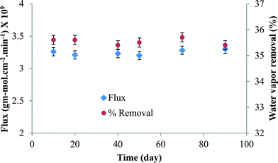 | ||
| Fig. 6 The membrane performance in terms of water vapor flux and % water vapor removal with time (at 25 °C and 68% RH). | ||
Mechanism of water permeation in CNIM-SAP
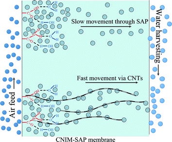
Mechanistically speaking, the permeation of water vapor molecules through a polymeric membrane is proposed to occur in several successive steps. This is shown in Fig. 7. Initially, the moisture in the feed was absorbed on the membrane surface and in the free spaces within the membrane. These absorbed molecules then diffused across the membrane to the permeate side. The strong interaction between water and the SAP is an important consideration. The water in the SAP membrane can be classified as bound, semi-bound and free water.48 The SAP molecules strongly interact with the ‘bound water’ and physically restrict its permeation by creating a gel. The portion of water molecules that does not participate in hydrogen bonding with the polymer is termed as ‘free water’. The amount of free water depends upon the water–polymer interactions49 and the ability of the water to form clusters within the free space of the membrane.50The CNTs likely interact with water via multiple mechanisms. The presence of hydrophobic CNTs reduces hydrogen bonding among the water molecules and with the SAP.51 It is also well known that the CNTs show high hydraulic conductivity due to liquid slip at the solid–liquid boundary, subcontinuum alteration of dipole orientation and apparent reduction in liquid viscosity on the CNT surface.52,53 In short, the enhancement of flux in CNIM-SAP is due to the ability of the CNTs to influence water–polymer interactions54,55 leading to the generation of more free water that can be easily transported along frictionless CNTs which have been referred to as the ‘fast lanes’ for water flow.56
Conclusions
The highly hydrophilic CNIM-SAP was successfully employed to harvest water vapor from air. This approach is a viable alternative to existing water supply systems. The presence of CNTs led to higher amounts of water vapor being extracted which increased with relative humidity. The CNIM-SAP demonstrated several advantages over a membrane without CNTs including enhancement in water vapor removal by as much as 52%, and 44% enhancement in mass transfer coefficients. The water vapor flux and the mass transfer coefficient of the membrane reached as high as 28.31 × 10⁻⁹ gm mol cm−2 min−1 and 8.14 × 10⁻⁷ m s−1, respectively. Some of these features make the CNIM-SAP an excellent membrane for harvesting pure water from air.References
- D. Breschi, Desalination, 1999, 122, 247–254 CrossRef CAS.
- A. L. A. Malik, N. G. Younan, B. J. R. Rao and K. M. Mousa, Desalination, 1989, 75, 341–361 CrossRef CAS.
- L. D. Nghiem, C. Elters, A. Simon, T. Tatsuya and W. Price, Sep. Purif. Technol., 2015, 146, 94–100 CrossRef CAS PubMed.
- F. Macedonio, A. Ali, T. Poerio, E. El-Sayed, E. Drioli and M. Abdel-Jawad, Sep. Purif. Technol., 2014, 126, 69–81 CrossRef CAS PubMed.
- A. Scrivani, T. El Asmar and U. Bardi, Desalination, 2007, 206, 485–493 CrossRef CAS PubMed.
- S. Roy, M. Bhadra and S. Mitra, Sep. Purif. Technol., 2014, 136, 58–65 CrossRef CAS PubMed.
- F. Macedonio, E. Drioli, A. A. Gusev, A. Bardow, R. Semiat and M. Kurihara, Chem. Eng. Process.: Process Intesif., 2012, 51, 2–17 CrossRef CAS PubMed.
- H. Sijbesma, K. Nymeijer, R. Marwijk, R. Heijboer, J. Potreck and M. Wessling, J. Membr. Sci., 2008, 313, 263–276 CrossRef CAS PubMed.
- R. Ahvenainen, Trends Food Sci. Technol., 1996, 7, 179–187 CrossRef CAS.
- J. Haas and A. Sauterleute, US Pat., 7,017,365, March 28, 2006 Search PubMed.
- A. Scrivani and U. Bardi, Desalination, 2008, 220, 592–599 CrossRef CAS PubMed.
- R. V. Wahlgren, Water Res., 2001, 35, 1–22 CrossRef CAS.
- B. Bolto, M. Hoang and Z. Xie, Water Res., 2012, 46, 259–266 CrossRef CAS PubMed.
- W. E. Alnaser and A. Barakat, Appl. Energy, 2000, 65, 3–18 CrossRef CAS.
- L. Jia, X. F. Peng, J. D. Sun and T. B. Chen, Heat Tran. Asian Res., 2001, 30(7), 571–580 CrossRef PubMed.
- Y. H. Zurigat, M. K. Abu-Arabi and S. A. Abdul-Wahab, Energy Convers. Manage., 2004, 45(1), 141–155 CrossRef CAS.
- A. Ito, J. Membr. Sci., 2000, 175(1), 5–42 CrossRef.
- L. Z. Zhang, Sep. Sci. Technol., 2006, 41(8), 1565–1582 CrossRef CAS PubMed.
- K. L. Wang, S. H. McCray, D. D. Newbold and E. L. Cussler, J. Membr. Sci., 1992, 72(3), 231–244 CrossRef CAS.
- Z. G. Wang, T. L. Chen and J. P. Xu, Macromolecules, 2001, 34(26), 9015–9022 CrossRef CAS.
- N. Hengl, A. Mourgues, E. Pomier, M. P. Belleville, D. Paolucci-Jeanjean, J. Sanchez and G. Rios, J. Membr. Sci., 2007, 289(1–2), 169–177 CrossRef CAS PubMed.
- B. Bolto, M. Hoang and Z. Xie, Water Res., 2012, 46, 259–266 CrossRef CAS PubMed.
- S. M. Allen, M. Fujii, V. Stannett, H. B. Hopfenberg and J. L. Williams, J. Membr. Sci., 1977, 2, 153–164 CrossRef CAS.
- S. J. Metz, W. J. C. van de Ven, J. Potreck, M. H. V. Mulder and M. Wessling, J. Membr. Sci., 2005, 251(1–2), 29–41 CrossRef CAS PubMed.
- L. Jia, X. F. Xu, H. J. Zhang and J. P. Xu, J. Polym. Sci., Polym. Phys. Ed., 1997, 35, 2133–2140 CrossRef CAS.
- J. A. Barrie, Proceedings of the Fourth BOC Priestly Conference, 1986, pp. 89–113 Search PubMed.
- Q. Zhao, P. Majsztrik and J. Benziger, J. Phys. Chem. B, 2011, 115, 2717–2727 CrossRef CAS PubMed.
- C. M. Hussain, C. Saridara and S. Mitra, Analyst, 2008, 133, 1076–1082 RSC.
- J. K. Holt, H. G. Park, Y. Wang, M. Stadermann, A. B. Artyukhin, C. P. Griporopolous, A. Noy and O. Bakajin, Science, 2006, 312, 1034–1037 CrossRef CAS PubMed.
- G. Hummer, J. C. Rasaiah and J. P. Nowortya, Nature, 2001, 414, 188–190 CrossRef CAS PubMed.
- B. J. Hinds, N. Chopra, T. Rantell, R. Andrews, V. Gavalas and L. Bachas, Science, 2004, 303, 62–65 CrossRef CAS PubMed.
- A. Noy, H. G. Park, F. Fornasiero, J. K. Holt, C. P. Grigoropoulos and O. Bakajin, Nano Today, 2007, 2, 22–29 CrossRef.
- H. Chen and D. S. Sholl, J. Membr. Sci., 2006, 269, 152–160 CrossRef CAS PubMed.
- O. Sae-Khow and S. Mitra, Anal. Chem., 2010, 82(13), 5561–5567 CrossRef CAS PubMed.
- S. Roy, S. A. Ntim, S. Mitra and K. K. Sirkar, J. Membr. Sci., 2011, 375(1–2), 81–87 CrossRef CAS PubMed.
- O. Sae-Khow and S. Mitra, J. Phys. Chem. C, 2010, 114, 16351–16356 CAS.
- M. Bhadra, S. Roy and S. Mitra, Sep. Purif. Technol., 2013, 120, 373–377 CrossRef CAS PubMed.
- Y. Chen, Z. Iqbal and S. Mitra, Adv. Funct. Mater., 2007, 17, 3946–3951 CrossRef CAS PubMed.
- J. G. Wijmans and R. W. Baker, J. Membr. Sci., 1995, 107, 1–21 CrossRef CAS.
- B. K. Dutta and S. K. Sikdar, Environ. Sci. Technol., 1999, 33, 1709–1716 CrossRef CAS.
- W. J. Thomas and B. D. Crittenden, Processes and Cycles, Adsorption Technology and Design, Butterworth-Heinemann, Oxford, 1998, pp. 96–134 Search PubMed.
- M. J. Carmo and J. C. Gubulin, Braz. J. Chem. Eng., 1997, 14, 217–224 CAS.
- H. A. A. Farag, M. M. Ezzat, H. Amer and A. W. Nashed, Alexandria Eng. J., 2011, 50, 431–439 CrossRef CAS PubMed.
- P. J. Flory, Principles of Polymer Chemistry, Cornell University Press, Ithaca, NY, 1973 Search PubMed.
- E. E. Shafee and H. F. Naguib, Polymer, 2003, 44, 1647–1653 CrossRef CAS.
- C. E. Roger, Permeation of gases and vapors in polymersPolymer Permeability, ed. J. Comyn, Elsevier Applied Science, New York, 1985, p. 32 Search PubMed.
- E. F. Castro, E. E. Gonzo and J. C. Gottifredi, J. Membr. Sci., 1996, 113, 57–64 CrossRef CAS.
- X. Liu, X. Li, Z. Lu, X. Miao and Y. Feng, J. Polym. Res., 2011, 18, 897–905 CrossRef CAS.
- X. Qu, A. Wirsen and A. C. Albertsson, Polymer, 2000, 41, 4589–4598 CrossRef CAS.
- A. Carlsson, B. Lindman and P. G. Nilsson, Polymer, 1986, 27, 431–436 CrossRef CAS.
- E. Bekyarova, Y. Hanzawa, K. Kaneko, J. Silvestre-Albero, A. Sepulveda-Escribano, F. Rodriguez-Reinoso, D. Kasuya, M. Yudasaka and S. Iijima, Chem. Phys. Lett., 2002, 366, 463–468 CrossRef CAS.
- H. Verweij, M. C. Schillo and J. Li, Small, 2007, 3, 1996–2004 CrossRef CAS PubMed.
- S. Kar, R. C. Bindal and P. K. Tiwari, Nano Today, 2012, 7, 385–389 CrossRef CAS PubMed.
- S. Y. Hu, Y. Zhang, D. Lawless and X. Feng, J. Membr. Sci., 2012, 417–418, 34–44 CrossRef CAS PubMed.
- A. M. Sajjan, B. K. Jeevan Kumar, A. A. Kittur and M. Y. Kariduraganavar, J. Membr. Sci., 2013, 425–426, 77–88 CrossRef CAS PubMed.
- D. Mattia, H. Leese and K. P. Lee, J. Membr. Sci., 2015, 475, 266–272 CrossRef CAS PubMed.
Footnote |
| † Electronic supplementary information (ESI) available. See DOI: 10.1039/c5ew00098j |
| This journal is © The Royal Society of Chemistry 2015 |

