Reduction of microbial contamination from drinking water using an iron oxide nanoparticle-impregnated ultrafiltration mixed matrix membrane: preparation, characterization and antimicrobial properties
Received
26th November 2014
, Accepted 6th January 2015
First published on 7th January 2015
Abstract
Iron oxide nanoparticles were prepared and mixed in polyacrylonitrile to produce an ultrafiltration flat sheet mixed matrix membrane with high flux and adequate antimicrobial properties. Membranes with a molecular weight cut-off in the range of 48 to 65 kDa were obtained by varying the concentration of iron oxide nanoparticles. The cast membranes were characterized by scanning electron microscopy, permeability, molecular weight cut-off, contact angle, porosity, pore size distribution, surface area and mechanical strength. The antibacterial activity of the iron oxide nanoparticles on Escherichia coli was explored and confirmed by using confocal microscopy and scanning electron microscopy. The efficacy of the mixed matrix membrane to remove the total microorganisms and coliforms was analyzed using tap water. Adsorption of microorganisms (Escherichia coli) on the mixed matrix membrane was quantified. A minimum dose of 0.4 wt% of iron oxide nanoparticles completely inhibited the growth of microorganisms. Effects of operating conditions, namely transmembrane pressure and cross flow rate, on the system performance were also investigated.
Water impact
Millions of people suffer from water-borne diseases due to microbial contamination in the surface and groundwater. According to the World Health Organization, there should not be any coliform present in drinking water. To address this critical issue, the present work provides a novel mixed matrix membrane (MMM) using iron oxide nanoparticles impregnated in polyacrylonitrile. The paper demonstrates the high bacterial killing potential of the developed MMM compared to the membrane without nanoparticles. The study reveals the strong anti-fouling properties of the MMM and no leaching of nanoparticles in treated water.
|
1. Introduction
Microbiological contamination of water sources has been a major concern.1 Millions of people in various parts of the world suffer from water-borne diseases.1,2 A variety of bacterial species are available in raw water as well as in wastewater.1,3 Chlorination, ozonation and ultraviolet (UV) treatment are the most common techniques for water disinfection.4 However, chlorination may lead to release of toxic and carcinogenic derivatives of chloramines.4 Existence of resistant microorganisms and high cost of the reactors are the limitations for UV treatment.5 Ozonation may produce undesirable toxic by-products like formaldehyde, bromate and other assimilable organic carbon. In this regard, membrane-based technology is a promising disinfection method where microorganisms are retained without any harmful chemical treatment.6 Microfiltration (MF) is useful in water purification due to its efficiency to remove microorganisms and dissolved organic matter (DOM).6 Ultrafiltration (UF) has been reported to represent 74% of the total membrane installations for water purification in order to meet the stringent quality of potable water.7 However, biofouling is a critical issue that is encountered during the membrane filtration process due to deposition of microbial cells or other organic matter present in the feed stream.8 Biofouling leads to the decline of permeate flux and hence low throughput of the membrane.9,10
Many studies have been performed to overcome membrane fouling due to accumulation and subsequent growth of microorganisms.9,10 To address the issue of biofouling of the membrane, the explored techniques include membrane modification and low flux operation.11 Incorporation of inorganic particles in a polymeric matrix, known as the mixed matrix membrane (MMM), is one of the latest developments in the field of membrane modification.11,12 MMMs exploit the adsorption properties of inorganics and filtration capability of the porous polymeric matrix. Various inorganic fillers, namely, zeolite, silica and metal oxides, have contributed to enhance membrane performance, specifically in addressing flux decline and selectivity.13,14 Vicentini et al. (2010) cast the MMM using zinc oxide nanoparticles and chitosan–polyvinyl alcohol.2 They observed enhanced mitigation of Staphylococcus aureus bacteria species in spiked solution.
Recently, a number of studies indicated that impregnation of silver nanoparticles (AgNPs) as a potential antibacterial agent in the polymer matrix to form a MMM with antifouling property.15 An et al. (2009) studied the capability of an electrospun chitosan–polyethylene oxide membrane impregnated by silver for removal of E. coli. The study revealed complete inhibition of E. coli within 10 hours. Taurozzi et al. (2008) proposed the antibiofouling nature of a polysulfone–silver nanocomposite membrane due to ionic silver release.16 Cao et al. (2010) investigated the antibacterial effect of AgNPs in a polyethersulfone membrane using Staphylococcus aureus, Staphylococcus albus and E. coli as experimental organisms.17 The study demonstrated strong antimicrobial properties of the membrane. Diagne et al. (2012) modified a commercially available polyethersulfone membrane by a polyelectrolyte multilayer modification method using poly(styrenesulfone), poly(diallyldimethylammonium chloride) and AgNP.18 Experimental results showed that the membrane modified with AgNPs was resistant to biofouling and also inhibited bacterial growth. Basri et al. (2010) reported 100% removal of Staphylococcus aureus and E. coli using a silver-filled polyethersulfone membrane.19 However, leaching of silver to the filtrate is the major issue.15–19 In addition, AgNPs are expensive and their synthesis techniques involve toxic, hazardous chemicals which may cause an environment risk.20 Besides, AgNPs tend to penetrate the circulatory system and translocate the blood–brain barrier within the human body. Studies also suggest that it is difficult to remove AgNPs once deposited in the body causing adverse health hazard to humans.21
Exploration of iron oxide (Fe3O4) nanoparticles in a mixed matrix membrane is a recent research trend due to their adsorption properties, cost-effectiveness and non-toxicity.22 Shinde et al. (2012) prepared an Fe3O4–polypropylene flat sheet membrane to remove arsenic(V) from water.23 Zhang et al. (2009) cast and characterized Fe3O4–polyacrylonitrile (PAN) electrospun-fiber media.24 Daraei et al. (2012) prepared an Fe3O4–polyethersulfone–polyanile MMM and showed its efficacy to remove Cu(II).25 However, none of the above studies addressed the antimicrobial and antifouling properties of the membrane.
The antibacterial properties of Fe3O4 nanoparticles are well known as these are nontoxic and show strong antimicrobial activity for a number of bacteria and viruses.26 Lee et al. (2008) demonstrated the oxidative stress-mediated inactivation of E. coli cells, exploiting zero-valent iron nanoparticles.27 Dallas et al. (2010) reported the enhanced antibacterial activity of a silver/iron nanocomposite.28 Prucek et al. (2011) showed the antimicrobial efficacy of silver/iron binary nanoparticles against ten bacterial strains and four Candida species.29 Durmus et al. (2013) demonstrated that Fe3O4 nanoparticles can penetrate an antibiotic resistant biofilm in the presence of fructose metabolites.30 According to previous research, Fe3O4 nanoparticles have strong antimicrobial properties, although these are nontoxic to mammalian cells and cost effective.22–30 Thus, it is expected that a MMM prepared with an Fe3O4-doped polymer like PAN would have strong antimicrobial properties.
Therefore, an attempt has been made in the present work to exploit the antimicrobial properties of amine-stabilized Fe3O4 nanoparticles in a PAN MMM for water treatment. To the best of the authors' knowledge, this is the first ever attempt to explore the possibility of Fe3O4 in a PAN-based MMM as an antibacterial agent. The membranes were characterized in terms of surface morphology, porosity, permeability, contact angle, molecular weight cut-off, pore size distribution, surface area and mechanical strength. The adsorption of E. coli by the MMM was also quantified. The appropriate composition of the MMM was identified, and the efficacy of this membrane towards the removal of microorganisms from tap water (6.9 × 10⁴ CFU ml−1) was investigated as a function of the operating parameters, namely, transmembrane pressure drop (TMP) and cross flow rate. The improvements in leaching and antifouling nature of the MMM were also studied.
2. Experimental
2.1 Materials
Polyacrylonitrile (PAN) (with an average molecular weight of 50 kDa, homopolymer) from M/s, Technorbital, Kanpur, India, was used as the base polymer. Solvent N-methyl-2-pyrrolidone (NMP), ferrous sulphate (heptahydrate), ammonia solutions (25%), nutrient broth and nutrient agar (pH 7.0) were purchased from M/s, Merck (India) Ltd., Mumbai, India. Ferric chloride (hexahydrate), glutaraldehyde and ethanolamine (purity 99%) were purchased from Loba Chemie, Mumbai, India. Polyethylene glycol (PEG) (with molecular weights of 0.4, 4, 6, 10, 20, 35 and 100 kDa), lauryl tryptose broth and brilliant green lactose bile broth were supplied by M/s, S R Ltd., Mumbai, India. Neutral solutes of PEG were used to find the molecular weight cut-off (MWCO) of the cast membranes.
2.2 Synthesis of iron oxide nanoparticles (Fe3O4)
Typically 2 g of ferric chloride and 1 g of ferrous sulphate were dissolved into 50 ml of distilled water. Ammonia solution was added to this mixture under vigorous stirring. 10 ml of ethanolamine was used as a capping agent. The mixture was heated at 80 °C. The black precipitate was thoroughly washed several times with distilled water and then with acetone. The nanoparticles were dried at room temperature and ground into powder.
2.3 Characterization of nanoparticles
High-resolution transmission electron microscopy (JEOL 3010, Japan) was used to characterize the microstructure of the nanoparticles. The size and zeta potential of the nanoparticles were measured using a zetasizer (model: Zetasizer nano ZS 90) supplied by M/s, Malvern Instruments, Worcestershire, England. The Brunauer–Emmett–Teller (BET) surface area was measured using a BET instrument, supplied by Quantachrome Instruments, Florida, USA (model: AUTOSORB-1). The presence of surface functional groups on the nanoparticles was investigated by Fourier transform infrared (FTIR) spectroscopy (supplied by M/s, Perkin Elmer, Connecticut, USA; model: Spectrum 100). The FTIR study was conducted in the range of 400–4000 cm−1.
2.4 Antibacterial properties of iron oxide nanoparticles
E. coli (ATCC 10![[thin space (1/6-em)]](https://www.rsc.org/images/entities/char_2009.gif) 536) cells were cultured in nutrient agar medium by a spread plate method.17 A single isolated colony was inoculated in 20 ml of nutrient broth medium and incubated for 24 hours at 37 °C. The bacterial culture was centrifuged at 10000 rpm for 15 minutes and the cells were washed thrice with phosphate buffer solution (0.01 M, pH 7). The E. coli cells were grown until it reached 105 CFU ml−1. To this bacterial suspension, 1 mg of iron oxide nanoparticles was added and incubated for 24 hours. It may be worth mentioning that cellular inactivation/morphological alteration of E. coli (105 CFU ml−1) was not attained when the dose of Fe3O4 was less than 1 mg.
536) cells were cultured in nutrient agar medium by a spread plate method.17 A single isolated colony was inoculated in 20 ml of nutrient broth medium and incubated for 24 hours at 37 °C. The bacterial culture was centrifuged at 10000 rpm for 15 minutes and the cells were washed thrice with phosphate buffer solution (0.01 M, pH 7). The E. coli cells were grown until it reached 105 CFU ml−1. To this bacterial suspension, 1 mg of iron oxide nanoparticles was added and incubated for 24 hours. It may be worth mentioning that cellular inactivation/morphological alteration of E. coli (105 CFU ml−1) was not attained when the dose of Fe3O4 was less than 1 mg.
Two typical studies, i.e., SEM and confocal microscopy (model: FV1000, Olympus, USA), of healthy E. coli cells and nanoparticle-treated cells were carried out to explore the efficacy of iron oxide nanoparticles as an antibacterial agent. For SEM analysis, bacterial cells were fixed with 2% glutaraldehyde and stained with 1% osmium tetroxide (supplied by Sigma Aldrich Chemicals, USA). The sample was then dehydrated with increasing concentrations of ethanol (25%, 50%, 75%, 95% and 100%) before gold coating.31 For confocal microscopy, a 10 μl green fluorescent dye (CellLight® Actin-GFP, supplied by Merck India Pvt. Ltd., Mumbai, India) was added to the bacterial suspension and incubated at 37 °C for 16–18 hours. It may be mentioned that the excitation and emission of the dye were 488 and 510 nm, respectively.
2.5 Membrane preparation
Flat sheet Fe3O4–PAN membranes were prepared by a phase inversion method and hand casting. Six sets of solutions were prepared by dissolving 15 wt% PAN in NMP separately at 60 °C. The solution was stirred with a mechanical stirrer for at least 8 hours to ensure complete dissolution of the polymer. Thereafter, Fe3O4 at different percentages (0.2 to 1 wt%) was added to the polymer solution, leaving one as blank (0 wt% Fe3O4). In the first step of casting of membranes, non-woven polyester fabric of 118 ± 22.8 μm thickness (product number TNW006013, supplied by M/s, Hollytex Inc., New York, USA) was attached to a clean glass plate using adhesive tape. The solution was drawn on the fabric using a casting knife with an adjustable gate height fixed at 200 μm. The cast solution was immediately immersed in a precipitation bath containing distilled water at room temperature to initiate the non-solvent induced phase separation. The membrane was allowed to be in the precipitation bath for 10 min, and then, it was transferred to another container with fresh distilled water and left for 24 hours to remove the excess solvent. After that, the membrane was ready to be characterized.
2.6 Characterization of membranes
2.6.1 Surface morphology.
The skin of the membrane was carefully removed from the substrate. The surface morphology of the membranes was observed using a scanning electron microscope (model: ESM-5800, JEOL, Japan) on the cross-section, top and bottom surfaces of the membrane.11
2.6.2 Membrane permeability.
Membrane permeability was measured in a batch filtration cell.11 The effective area of the membrane in the module was 34 cm2. First, the cell was filled with 500 ml of distilled water and the membrane was compacted at 690 kPa for 4 hours. The permeate flux was calculated as follows:where Jw is the pure water flux, Q is the volumetric flow rate of permeating water, A is the membrane area, and ΔT is the sampling time. Next, the value of the steady state permeate flux was noted at five TMP. A plot of Jw with TMP resulted in a straight line through the origin. From the slope of this curve, the membrane permeability was obtained.
2.6.3 Molecular weight cut-off (MWCO) of the membrane.
Solute rejection measurements were carried out in a stirred batch cell.11 Solutions of 20 kg m−3 using different neutral solutes, namely, polyethylene glycol (PEG) of molecular weights 0.4, 4, 6, 10, 20, 35 and 100 kDa, were prepared. The experiments were conducted at 276 kPa pressure and 1000 rpm. The permeate samples were analyzed using a digital refractometer (model no. 300034, manufacturer: SPER Scientific, supplied by Cole-Parmer, Kolkata, India). The rejection was computed as follows:| | | R = (1 − Cp/Cf) × 100% | (2) |
where Cp and Cf are the concentrations of the solutes in the permeate and feed, respectively. MWCO of the membrane was the molecular weight corresponding to 90% solute rejection.
2.6.4 Pore size distribution and surface area analysis.
Pore radius and surface area of MMMs were measured using a BET surface area analyzer.
2.6.5 Porosity (ε) and contact angle (CA).
Membrane porosity was measured by the mass loss of the wet membrane after its drying. The membrane, soaked in distilled water, was weighed after wiping surface water using a filter paper. The wet membrane was then placed in an air-circulating oven at 60 °C for 24 hours and further dried in a vacuum oven before measuring the dry weight until a constant mass was obtained.11 From the weights of the wet (w0) and dry samples (w1), the porosity of the membranes was calculated using the following equation:| |  | (3) |
where ε is the porosity, A is the average area of the membrane samples, l is the thickness of the membrane and ρw is the water density. The membrane porosity of each sample was measured three times, and the average values were reported. The contact angle was measured using a goniometer (M/s, Rame-Hart Instrument Co., New Jersey, USA; model number 200-F4) using a sessile drop method. The contact angle was measured at six different locations of the membrane, and the average value was reported.
2.6.6 Breaking stress and elongation at break.
Breaking stress and elongation at break of different membranes were determined using a universal testing machine (M/s, Tinius Olsen Ltd., Redhill, England; model: H50KS). Measurements were carried out at room temperature and at a strain rate of 15 mm min−1. The reported value was the average of three samples.
2.6.7 Atomic force microscopy (AFM).
An atomic force microscope (model: 5500 AFM, Agilent Technologies, USA) was used to measure the surface roughness pattern of the membranes. Membrane samples were cut into small pieces (area: 0.25 cm2) and were fixed on a glass plate (area: 0.5 cm2) with the help of double-sided tape. Imaging was done on a scan size of 10 μm × 10 μm in tapping mode.
2.7 Bacterial adsorption on the membrane
2.7.1 Equilibrium study.
E. coli cells were cultured in 100 ml of nutrient broth medium for 12 hours at 37 °C. After that, 1 ml of the culture was transferred to each of 6 different conical flasks containing the same medium. The conical flasks containing the bacterial culture was then incubated at 37 °C for another 24 to 36 hours until the cell number reaches 105 CFU ml−1. 100 ml of bacterial culture solutions of different concentrations (4.2 × 10⁵, 5.1 × 10⁵, 5.9 × 10⁵, 6.7 × 10⁵, 7.4 × 10⁵ and 8.1 × 10⁵ CFU ml−1) were transferred to six conical flasks. 0.5 g of the membrane (0.4 wt% Fe3O4–PAN MMM) was dipped into each flask, and the conical flasks were gently shaken at 37 °C for 24 hours at 150 rpm. A control experiment was also carried out with 0 wt% Fe3O4–PAN. It may be worth mentioning that 100 μl of bacterial solution was withdrawn and analyzed every hour. The equilibrium time was determined when there was no change in concentration of bacteria in consequent readings. The adsorption efficacy of the membrane was calculated by the difference between the initial and the final concentrations of bacteria, and the adsorption capacity was expressed as number per gram of the membrane.
2.7.2 Scanning electron microscopy imaging of the membrane after adsorption.
After adsorption, the membrane sample (0.4 wt% Fe3O4–PAN MMM) was prepared for SEM by a previously reported technique.31 Briefly, samples were fixed with 2% glutaraldehyde, washed and treated with 1% osmium tetroxide. The sample was then dehydrated with a graded ethanol series before gold coating. Bacterial morphology was studied on the membrane surface and compared with fresh E. coli cells.
2.7.3 Applicability of MMMs to remove microbes from water.
Two different experimental set-ups, i.e., unstirred batch cell and continuous cross flow cell, were used for this study. A batch cell was used to identify the suitable membrane among different Fe3O4–PAN MMMs in terms of microorganism removal. Continuous cross flow filtration was conducted under various operating conditions using the identified MMM.
2.7.4 Batch filtration setup.
Membranes were compacted for 4 hours at 690 kPa using distilled water. The feed for the experiment was collected from tap water in a sterilized narrow necked bottle. The experiments were conducted at 276 kPa. For each membrane, the duration of the filtration experiment was one hour. The pressure in the cell was maintained by using a nitrogen cylinder. The filtrate was collected carefully in a sterilized narrow necked bottle.
2.7.5 Cross flow experiment.
An indigenously designed rectangular cross-flow cell, made of stainless steel, was used for cross flow experiments. Two neoprene rubber gaskets were placed over the membrane forming the flow channel. The channel height after tightening the two flanges was found to be 3.0 × 10⁻³ m. The effective dimensions of the membrane were 14.5 cm in length and 5.5 cm in width. The cell consisted of two rectangular matching flanges. The inner surface of the top flange was mirror polished. The bottom flange was grooved, forming the channels for the permeate flow. A porous stainless steel plate was placed on the bottom flange providing mechanical support to the membrane. Two flanges were tightened to create a leak proof channel for conducting experiments in cross flow mode. The details of the cell were available.32
Cross flow experiments were performed with 0.4 wt% Fe3O4–PAN MMM. A fresh membrane was compacted at a pressure higher than the maximum operating pressure (552 kPa) for 4 hours using distilled water and then its permeability was measured. Three experiments were performed including variations of TMP and cross flow rate. These were 276 kPa and 40 l h−1, 276 kPa and 60 l h−1 and 414 kPa and 40 l h−1. The feed was placed in a feed tank of 5 l capacity. The duration of the experiment was ten hours. Values of permeate flux were determined from a cumulative volume versus time plot. A 10 ml sample was collected in a sterilized container every hour for microbial analysis. The permeate stream after collecting the required amount of sample was recycled to the feed tank to maintain a constant concentration.
2.7.6 Analysis of colony forming unit (CFU) and most probable number (MPN).
Feed and permeate samples were immediately analyzed for the CFU and MPN count. To calculate the colony forming unit, a 1 ml water sample (feed and permeate) was diluted 100 times in a test tube. From the dilution tube, 0.1 ml of the diluted solution was aseptically transferred to agar plates and carefully spread using a spreader. The plates were incubated at 37 °C for 24 h. This process was repeated for three plates. Each plate was observed for growth and colonies were counted visually. The average values of CFU ml−1 were reported. The following equation was used to calculate the number of colony forming units (CFU ml−1):33| |  | (4) |
An MPN test was also carried out in the feed and permeate samples to investigate the effectiveness of cast membranes on the removal of coliforms. Separate analyses were conducted on five parts of each of three serial dilutions of feed and permeate. The individual portion was used to inoculate tubes of lauryl tryptose broth culture medium and incubated at 35 ± 2 °C for 48 hours. The presence of coliforms was indicated by turbidity, pH change or the presence of gas in the culture medium. All positive tubes were recorded and inocula from each positive tube were carefully transferred to brilliant green lactose bile broth and incubated for another 48 hours at 35 ± 2 °C. The MPN index was determined by comparing the pattern of positive results (the number of tubes showing growth at each dilution) with statistical tables. The obtained value was reported as MPN per 100 ml of the sample.34 Tests for fecal coliforms in the feed gave negative results, and thus, it was not performed for permeate samples. It may be mentioned that CFU and MPN values indicated the total microorganisms and coliforms in the water sample.
2.7.7 Bacterial growth on the membrane.
The viability of bacteria retained on the membrane surface was quantified by a membrane agar test.35 After filtration, the membrane was kept on the nutrient agar plate placed upside down and incubated overnight at 37 °C. The number of visible colonies was counted. A similar study was carried out using a control membrane.
2.8 Water quality parameter
The following water quality parameters were analyzed with MMMs in the feed and filtrate: pH, conductivity, total dissolved solids (TDS), total salts as equivalent sodium chloride, potassium, sodium, chloride and iron. pH, conductivity and TDS were measured using a multi-parameter tester (model: PCSTestr 35, M/s, Eutech Instruments, Germany). Concentrations of potassium, sodium and chloride ions were measured using an ion selective electrode (supplied by M/s, Thermo Electron Corporation, Beverly, USA). Iron concentration was measured using an atomic absorption spectrophotometer (model: Analyst 700, M/s, Perkin Elmer, Connecticut, USA).
2.9 Assessment of iron leaching
To measure the amount of iron leached from the MMM during filtration, distilled water was filtered through the membrane for 10 hours under various operating conditions, i.e., 276 kPa and 40 l h−1, 276 kPa and 60 l h−1 and 414 kPa and 40 l h−1. A 10 ml sample was then collected in a container at the end of the experiment. Solutions with concentrations varying from 0.5 mg l−1 to 5 mg l−1 of iron were prepared by diluting a standard iron solution with a concentration of 1001 ± 2 mg l−1 in 2% nitric acid using double distilled water, for atomic absorption (procured from Merck, India Ltd., Mumbai, India). The absorbance values of these solutions were measured using an atomic absorption spectrophotometer (model: Analyst 700, M/s, Perkin Elmer, Connecticut, USA). The plot of concentration of iron and absorbance was a straight line through the origin and was used as a calibration curve. The permeate samples were then analyzed for iron concentration using an atomic absorption spectrophotometer.
3. Results and discussion
3.1 Characterization of iron oxide nanoparticles
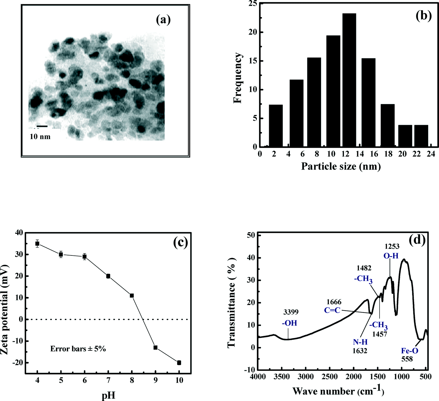
The transmission electron micrograph of iron oxide nanoparticles is presented in Fig. 1(a). It is observed in this figure that the nanoparticles have a spherical morphology. The particle size distribution of the nanoparticles is shown in Fig. 1(b). In this figure, it is observed that the range of size of nanoparticles is from 2 to 24 nm, with an average size of 13 nm. The zeta potential of the nanoparticles was measured after diluting the sample in 0.01 M phosphate buffers using a zetasizer. The zeta potential of the nanoparticles was estimated as a function of solution pH, and the results are shown in Fig. 1(c). It is clear in the figure that the pH (pHzpc) where the nanoparticles are neutral is 8.5. Thus, at normal pH of drinking water in the range of 6 to 7, the nanoparticles are positively charged. At pH beyond 8.5, the surface of the iron oxide nanoparticles is negatively charged. The surface area of the nanoparticles was 150 m2 g−1. Fourier transform infrared (FTIR) spectroscopy of iron oxide nanoparticles presented in Fig. 1(d) shows a broad band around 3399 cm−1, indicating the presence of –OH groups on the nanoparticle surface.36 The strong band around 558 cm−1 is a characteristic of the Fe–O vibration present in the magnetite core.36 A broad peak around 1666 cm−1 signifies a C![[double bond, length as m-dash]](https://www.rsc.org/images/entities/char_e001.gif) C bond.37 However, the peak at 1632 cm−1 is due to the bending of N–H, indicating the presence of the NH2 group.38 Peaks at 1482 cm−1 and 1457 cm−1 are associated with –CH3 stretching.39 The band at 1253 cm−1 corresponds to bending of the O–H group.40
C bond.37 However, the peak at 1632 cm−1 is due to the bending of N–H, indicating the presence of the NH2 group.38 Peaks at 1482 cm−1 and 1457 cm−1 are associated with –CH3 stretching.39 The band at 1253 cm−1 corresponds to bending of the O–H group.40
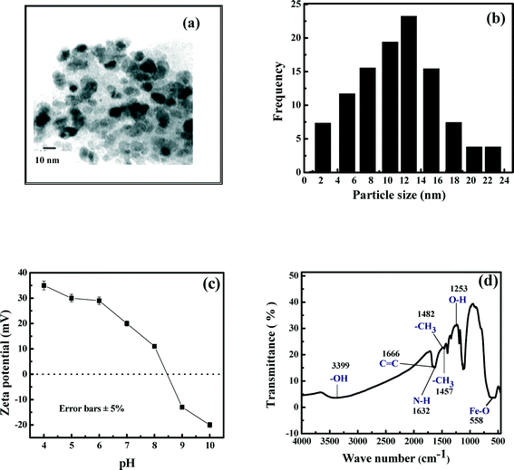 |
| | Fig. 1 Characterization of iron oxide nanoparticles. (a) TEM image; (b) particle size distribution; (c) zeta potential; (d) FTIR image. | |
3.2 Antibacterial properties of iron oxide nanoparticles
A scanning electron microscopy (SEM) image of freshly grown E. coli shows uniformly distributed cells with 1 μm thickness and 2 μm length (Fig. 2a). The outer membrane of the bacterial cell was intact before treatment with nanoparticles. However, after treatment, E. coli cells lose their cellular integrity with prominent disruption of the cell membrane (Fig. 2b). The bacterial cells seem to have corrugated due to the electrostatic interaction between positively charged nanoparticles and negatively charged E. coli cells (Fig. 2a and b), demonstrating antibacterial activity of iron oxide nanoparticles.
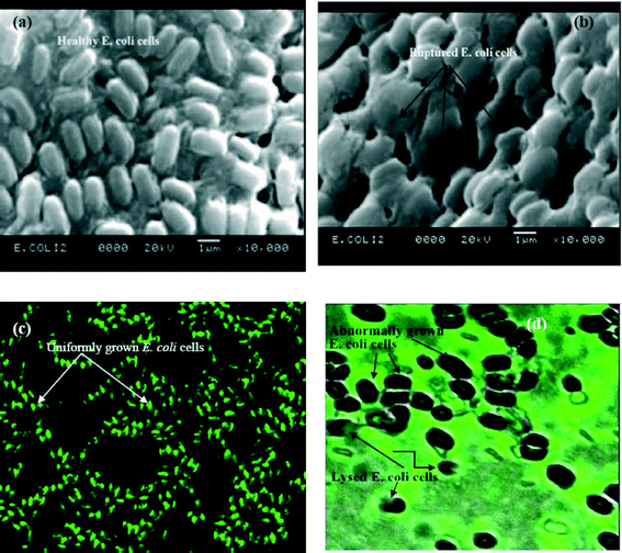 |
| | Fig. 2 Antimicrobial properties of iron oxide nanoparticles. (a) SEM image of E. coli cells before nanoparticle treatment; (b) SEM image of E. coli cells after nanoparticle treatment; (c) confocal microscopic image of E. coli cells before nanoparticle treatment; (d) confocal microscopic image of E. coli cells after nanoparticle treatment. | |
Confocal microscopy results show uniform distribution of bacterial cells with fluorescence properties before treatment with nanoparticles, indicating the viability of cells (Fig. 2c). However, the cellular morphology changes and they become bigger in size with an irregular shape after treatment with nanoparticles. The treated cells also become black and the fluorescence properties are almost absent as evident in Fig. 2d. It may be noted that the green fluorescent dye labels the cellular materials. Therefore, a close look at Fig. 2d reveals that the cellular material of bacteria may be released outside the cell, as nanoparticles get incorporated within it. Consequently, the cells lose their viability in the absence of the cellular material, thereby suppressing fluorescence properties. Thus, instead of labeling the cell, the dye gives fluorescence outside the cell. Hence it may be interpreted that iron oxide nanoparticles may lead to inactivation of bacteria by cellular disruption.26–30
3.3 Characterization of the PAN–iron oxide mixed matrix membrane
3.3.1 Surface morphology.
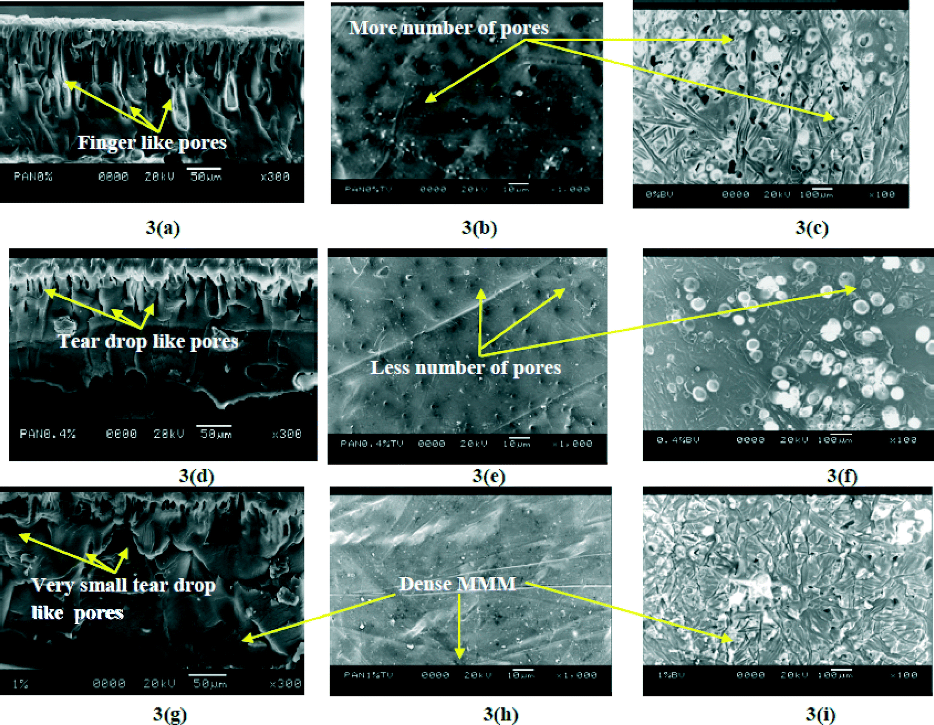
The surface morphology of the prepared membranes was analyzed using cross-sectional, top and bottom view SEM images of the membranes. These are presented in Fig. 3. Fig. 3(a), (d) and (g) show the cross-sectional views of the membranes with 0, 0.4 and 1 wt% Fe3O4 nanoparticles at the same magnification (300×). Fig. 3(b), (e) and (h) present the top views, and the bottom views of the corresponding membranes are shown in Fig. 3(c), (f) and (i). It is observed in Fig. 3(a) that the membrane is composed of a thin and dense skin layer, followed by a porous substructure in the middle and a spongy thick layer at the bottom, when there is no nanoparticle. The top layer of the MMM becomes denser with increasing nanoparticle concentration. The porous substructure shown in Fig. 3(a) consists of finger-like pores with an average diameter of 9.6 μm. It can be observed that there is a greater number of pores with a circular cross section. This morphology is a result of the quick demixing mechanism of the solvent–non-solvent interaction.41,42 The effect of addition of nanoparticles is observed in the subsequent figures. At 0.4 wt% Fe3O4 nanoparticles, it is observed in Fig. 3(d) that the finger-like pores have been changed to teardrop-like pores. The number of pores has also been reduced compared to 0 wt% Fe3O4. As the concentration of nanoparticles increased further to 1 wt%, the porous substructures are greatly suppressed (Fig. 3g). It is clear from the top and bottom views in Fig. 3(h) and (i) that the number of pores and their sizes have also reduced drastically with an increase in nanoparticle concentration. As the concentration of nanoparticles increases in the polymer matrix, pores are blocked, thereby reducing the porosity of the membranes. It is also possible that at higher concentration, nanoparticles agglomerate and pore constriction occurs to a greater extent. Thus, from the morphological analysis, it can be concluded that the membranes become denser with the concentration of Fe3O4 nanoparticles.
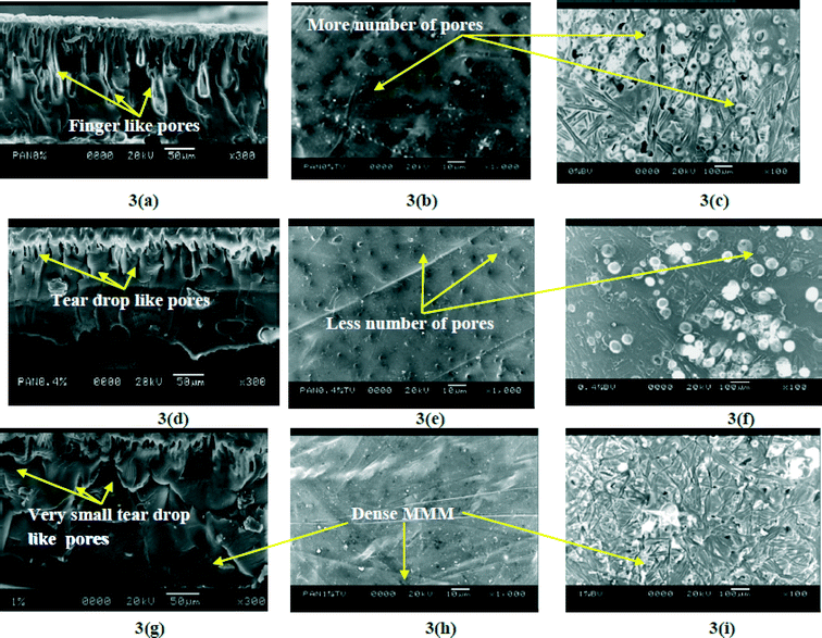 |
| | Fig. 3 SEM images of Fe3O4–PAN MMMs. (a, d, and g) Cross-sectional views of 0 wt%, 0.4 wt% and 1 wt% MMMs; (b, e, and h) top views of 0 wt%, 0.4 wt% and 1 wt% MMMs; (c, f, and i) bottom views of 0 wt%, 0.4 wt% and 1 wt% MMMs. | |
3.3.2 Porosity, contact angle and permeability.
Porosity, contact angle and permeability of the membranes are presented in Fig. 4 as a function of concentration of Fe3O4 nanoparticles. As observed in the figure, porosity and permeability decrease and contact angle increases with nanoparticle concentration. These observations are in perfect agreement with the morphological study presented in the preceding section. The membranes become denser with concentration of nanoparticles. For example, porosity of the membranes decreases from 74% to 48% as the concentration of the nanoparticles increases from 0 to 1 wt%. The corresponding decrease in permeability is from 10 × 10−11 to 4 × 10⁻¹¹ m Pa−1 s−1. As the membranes become denser, the hydrophilicity decreases as expected. This is reflected in an increase in the contact angle from 57° to 72°.
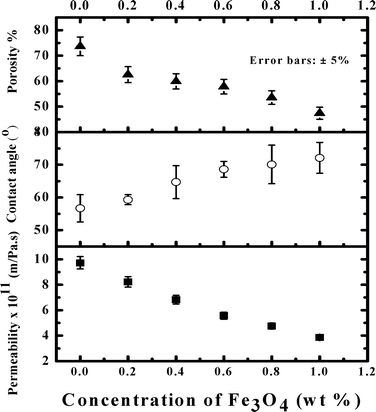 |
| | Fig. 4 Permeability, porosity and contact angle of various membranes. | |
3.3.3 Molecular weight cut-off.
Molecular weight cut-off (MWCO) of various membranes is presented in Fig. 5. As expected, MWCO of the membrane decreases with nanoparticle concentration as the membrane becomes denser. MWCO values of various membranes are 65, 62, 60, 58, 54 and 48 kDa for 0, 0.2, 0.4, 0.6, 0.8 and 1 wt% Fe3O4 concentrations.
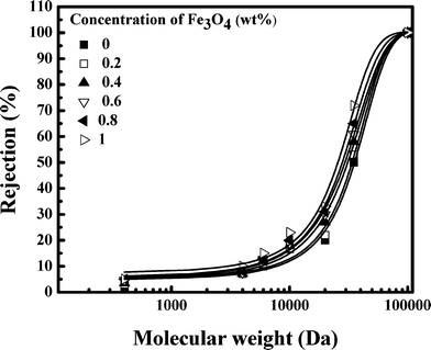 |
| | Fig. 5 Molecular weight cut-off (MWCO) of various membranes. | |
3.3.4 Pore size distribution and surface area.
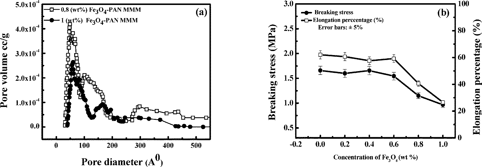
As described earlier, pore size distribution and surface area of the membranes were measured using a Brunauer–Emmett–Teller (BET) surface area analyzer. Two typical pore size distributions corresponding to 0.8 and 1.0 wt% Fe3O4 are presented in Fig. 6(a). Two trends are clear in this figure. First, for a fixed composition of the membrane, the majority of the pores are less than 100 Å with a peak at 50 Å for both cases. Second, the peak at 50 Å is reduced, indicating that the average pore size decreases as the concentration of Fe3O4 increases from 0.8 wt% to 1 wt%. There exist some pores with a diameter beyond 420 Å for the membrane with 0.8 wt% Fe3O4. The observation that the membranes become denser with the concentration of nanoparticles is in agreement with the SEM images. The average pore diameter of the membrane reduces from 112.5 Å to 72 Å as the concentration of Fe3O4 increases from 0 to 1 wt%. The specific surface areas of membranes with 0.4 and 1 wt% Fe3O4 are 12 m2 g−1 and 15 m2 g−1, respectively.
 |
| | Fig. 6 (a) Pore size distribution; (b) breaking stress and elongation percentage of Fe3O4–PAN MMMs. | |
3.3.5 Variation of breaking stress.
Variation of breaking stress and percentage elongation for various membranes are presented in Fig. 6(b). It is observed that the breaking stress remains almost unchanged at 1.6 MPa up to 0.4 wt% of Fe3O4 concentration and it decreases slightly thereafter. This observation indicates that beyond 0.4 wt%, the membrane becomes brittle and its breaking stress is reduced to 1 MPa at 1 wt% of Fe3O4. The elongation shows the corresponding behaviour. A similar trend is reported in the literature. Vicentini et al. (2010) found that the addition of zinc oxide nanoparticles significantly decreased the tensile strength of the chitosan–polyvinyl alcohol MMM.2
3.3.6 Atomic force microscopy (AFM).
AFM images of the membrane samples are presented in Fig. 7. The surface roughness values were also reported in terms of the mean absolute value of the difference (Ra). Different feature heights are given in the contour scale provided with the image. It was observed that with impregnation of nanoparticles, roughness gradually decreased and MMMs became smoother. The maximum roughness was found in the control membrane without nanoparticles. The roughness of 1 wt% Fe3O4–PAN MMM was least among all membranes, as contours were almost absent. In addition, the membrane became dense with impregnation of nanoparticles. The results directly corroborate with the SEM morphology of MMMs.
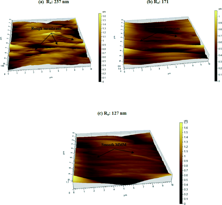 |
| | Fig. 7 Atomic force microscopy (AFM) images of MMMs. (a) 0 wt% MMM; (b) 0.4 wt% MMM; (c) 1 wt% MMM. | |
Several studies support that a rough membrane is more susceptible to biofilm formation by clogging. Bacterial cells can easily be deposited within the valleys of the membrane surface which may further increase the formation of a gel type layer. As a result, productivity as well as longevity of the membrane gradually decreases.41–46 On the contrary, biofilm formation is hindered in a smooth membrane due to the absence of contours.46 Our experimental results indicate that MMMs may possess antifouling properties and may prove effective in the long run as an antibacterial membrane as compared to a control membrane (0 wt% Fe3O4–PAN MMM).
3.4 Adsorption of E. coli on a mixed matrix membrane
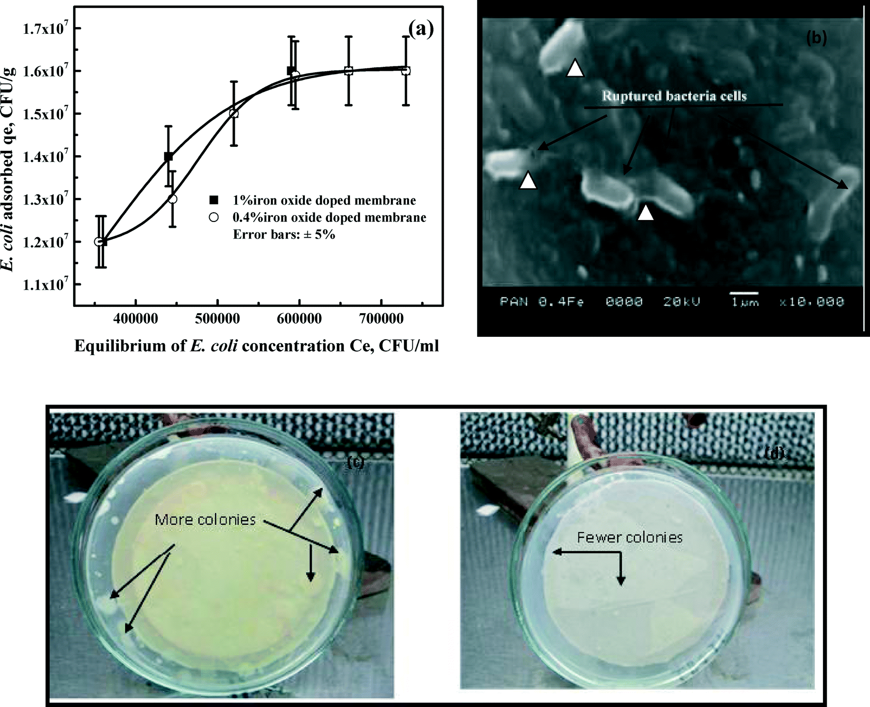
Equilibrium adsorption of E. coli on 0.4 wt% and 1 wt% of Fe3O4 MMMs was conducted, and the results are shown in Fig. 8(a). We found that the control sample was unable to adsorb bacteria as there was no difference between the initial and the final concentrations of bacteria. It was found that beyond 24 hours, the E. coli concentration does not change significantly. Thus, the equilibrium time of E. coli was considered as 24 hours. The adsorption isotherm for both membranes is quite close (R2 ≥ 0.98) and can be represented by a single equation in the form of a Langmuir isotherm:| |  | (5) |
 |
| | Fig. 8 Antimicrobial properties of MMMs. (a) Adsorption of E. coli on Fe3O4–PAN MMM (conc. of 1 wt% and 0.4 wt% Fe3O4); (b) SEM image of E. coli cells on MMM after the adsorption study; (c) bacterial growth on the control membrane; (d) bacterial growth on Fe3O4–PAN MMM (conc. of 0.4 wt% Fe3O4). | |
The maximum adsorption capacities (Vm) and adsorption constants (k) of both MMMs (0.4 wt% and 1 wt%) are calculated from the above equation and the average value is reported. The average values of Vm and k are 2.5 × 10⁷ colony forming unit g−1 (CFU g−1) and 2.03 × 10⁻⁶ ml CFU−1, respectively.
The positive charge of Fe3O4 nanoparticles facilitates electrostatic disruption of bacteria. Being anionic, bacterial cells are strongly adsorbed to the MMM by electrostatic attraction. This interaction with nanoparticles may lead to cellular disruption,47–49 thereby reducing the concentration of bacteria. However, results in Fig. 8(a) clearly shows that the performance of the MMM with 0.4 wt% Fe3O4 is close to that with 1 wt% Fe3O4.
3.5 Scanning electron microscopy imaging of the membrane after adsorption
Immediately after adsorption, a microscopic image of the MMM was taken. A SEM image of a healthy E. coli (1000×) culture showed uniformly grown elongated cells with normal size (thickness 1 μm and length 2 μm) and shape. However, after adsorption, the SEM image showed disruption and change in cellular integrity of E. coli on the membrane surface (Fig. 8b). Some of the cells are found to be damaged after adsorption (denoted by triangles). The possible mechanism for adsorption is that anionic cells of bacteria are electrostatically attracted to cationic Fe3O4 nanoparticles impregnated in the MMM. This interaction may lead to disruption of the outer membrane of bacteria causing morphological alteration as evident in the SEM image (Fig. 8b). The study directly corroborates with the reported literature.26 In addition, the SEM image does not show accumulation of bacterial cells on the membrane surface confirming that the MMM is resistant to biofilm formation.
3.6 Bacterial growth on the membrane
The membrane agar test showed that about 100 ± 5 colonies were formed in the plate with the control (Fig. 8c) membrane, whereas only 10 ± 2 colonies were grown in the plate with 0.4 wt% Fe3O4–PAN MMM (Fig. 8d). Most of the retained bacteria on the MMM lose their viability due to disruption of the cell and fail to re-grow. However, the majority of bacteria in the control membrane remain under viable conditions and re-grow. The results further confirm the potential of the MMM as a strong antibacterial membrane as well as its resistance to biofouling. In contrast, the control membrane is more vulnerable to biofouling. The finding is in agreement with the AFM and SEM images (Fig. 7 and 8b).
3.7 Selection of a suitable membrane for removal of the microorganism
Among five MMMs, the most suitable one was selected based on the experiments conducted in an unstirred batch cell in terms of rejection of the microorganism and permeate flux using tap water with prior report of the microorganism. The performance of various membranes is presented in Fig. 9(a). It is observed in Fig. 9(a) that the rejection (at the end of one hour) of the microorganism increases with Fe3O4 concentration up to 0.4 wt% and it remains invariant thereafter. Interestingly, 60% removal of the microorganism is achieved by the membrane without nanoparticles. Similarly in the most probable number (MPN) study, 80% removal of the total coliforms is achieved by the 0 wt% membrane. These observations indicate that the membrane without nanoparticles can separate microorganisms to some extent by size exclusion. With an increase in concentration of Fe3O4 nanoparticles, the removal of microorganism increases due to surface adsorption. However, the rejection is 100% for both the total coliforms (MPN/100 ml) and total microorganisms (CFU ml−1) at 0.4 wt% and higher concentration of Fe3O4. This simply shows that a MMM with 0.4 wt% Fe3O4 is sufficient to remove 100% microorganism of concentration in the feed (6.9 × 10⁴ CFU ml−1).
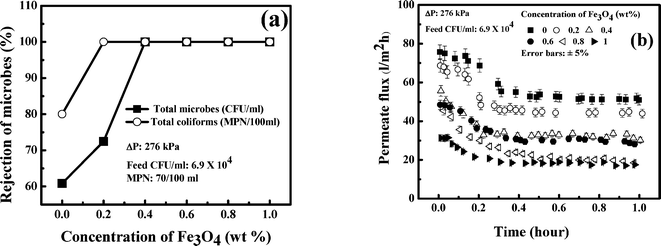 |
| | Fig. 9 Selection of a suitable membrane among various MMMs. (a) Microbe rejection in a batch cell; (b) flux decline in a batch cell. | |
The corresponding profiles of permeate flux are presented in Fig. 9(b). It is observed in this figure that an almost steady state permeate flux is attained after 10 minutes of operation. The quasi-steady values of permeate flux is according to the permeability of various membranes. The flux is maximum at 50 l m−2 h for the membrane without nanoparticles. It decreases with the concentration of nanoparticles in the membrane and attains a value of 30 l m−2 h for 0.4 wt% MMM. For 1 wt% MMM, the quasi steady state flux is 18 l m−2 h. A close look at Fig. 9, therefore, reveals that the MMM with 0.4 wt% Fe3O4 results in 100% removal of the microorganism with a reasonable permeate flux of 30 l m−2 h. Thus, 0.4 wt% Fe3O4 MMM is selected for removal of microorganisms with parametric variation of the operating conditions in a continuous cross flow filtration unit.
3.8 Effects of the operating conditions for cross flow experiments
In order to observe the effects of the operating conditions, namely, TMP and cross flow rate, the experiments are conducted in continuous mode of operation for 10 hours using tap water.
The rejection profile of the microorganism is shown in Fig. 10(a). It is observed in this figure that 100% removal is attained at 276 kPa. However, the results remain the same as the cross flow rate is increased from 40 to 60 l h−1. As TMP increases to 414 kPa, the rejection decreases continuously, and at the end of 10 hours, it is 87%. With an increase in TMP, convective flux dominates, leading to permeation of more microorganisms, thereby decreasing the rejection. It is reported that at higher TMP, increased drag force leads to reduction of the cell volume of bacteria. As a result, bacterial cells may easily permeate through the membrane retaining its pathogenicity.43,50–52 Thus, low pressure operation would be more favorable.
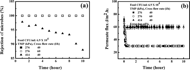 |
| | Fig. 10 Effects of operating conditions. (a) Microbe rejection by 0.4 wt% Fe3O4 MMM in a cross flow cell; (b) flux decline by 0.4 wt% Fe3O4 MMM in a cross flow cell. | |
The profiles of permeate flux under corresponding operating conditions are shown in Fig. 10(b). It is observed in this figure that the steady state permeate flux is 30 l m−2 h at 276 kPa and it is 60 l m−2 h at 414 kPa and 40 l h−1 cross flow rate. This trend is expected due to an increase in driving force. However, the effect of cross flow rate is marginal. The permeate flux remains at 30 l m−2 h if the cross flow rate increases from 40 to 60 l h−1. In the tap water, there is no higher molecular weight solute to foul the membrane, leading to the insignificant effect of the cross flow rate. By considering rejection of the microorganism and throughput of the membrane, 276 kPa TMP and 40 l h−1 cross flow rate can be selected as the desired operating conditions for microorganism-free drinking water. It is also clear in this figure that the life of this membrane is beyond 10 hours with an area of 0.01 m2. The life of the membrane is, therefore, much longer for a higher surface area in a scaled-up filter.
3.9 Water quality parameter
As outlined in section 2.8, various water quality parameters in the feed were given as follows: pH, 6.47; conductivity, 197 μs cm−1; total dissolved solids (TDS), 142 mg l−1; potassium, 0.7 mg l−1; sodium, 0.6 mg l−1; chloride, 27 mg l−1; and iron, 0.11 mg l−1. However, after filtration by 0.4 wt% Fe3O4 MMM, TDS decreased by 5% and iron decreased by 25%. Changes in the rest of the parameters were marginal.
3.10 Assessment of iron leaching
The iron concentration in the permeate was always below the detection limit for each operating condition. These observations suggests that the MMM is suitable for long term performance.
3.11 Removal mechanism of microorganisms by the MMM
The two prevalent mechanisms for removal of microorganisms by the MMM are size exclusion and adsorption. As observed in Fig. 9(a), 60% removal of the total microorganisms and 80% removal of the total coliform were attained by the membrane without nanoparticles. This indicates that majority of the microorganisms have sizes larger than the pore size of the membrane (with an average pore diameter of 84 Å). Thus, size exclusion is the major mechanism for removal of microorganisms in the control membrane.53 The role of Fe3O4 nanoparticles as a strong antimicrobial agent is also evident (Fig. 2a–d). The zeta potential of E. coli was measured as −40 mV using a zetasizer. At pH 6.7, the nanoparticles were positively charged due to immobilization of the amine group on their surface (Fig. 1c). Thus, negatively charged E. coli cells are attracted towards the nanoparticles on the membrane surface and readily get adsorbed, due to electrostatic interaction.26 The reactive oxygen species and hydroxyl radicals that may be generated by Fe3O4 could lead to oxidation of biomolecules such as lipopolysaccharide and DNA.26 This phenomenon leads to disruption of the cell (Fig. 2 and 8b) and ultimately causes bacterial inactivation. The antibacterial properties of the MMM is also evident in Fig. 8(a)–(d) and the adsorption isotherm presented in eqn (5). The electrostatic interaction between the microorganisms and Fe3O4 nanoparticles facilitates adsorption of microorganisms on the MMM, as evident from the SEM image (Fig. 8a to b). These findings are in agreement with the literature.47,48,50 However, the control membrane does not show any antibacterial properties, confirming that only size exclusion is the prevailing mechanism for those without nanoparticles. Thus, nanoparticles offer a unique disinfection feature in the MMM. The AFM study also confirms that impregnation of Fe3O4 nanoparticles makes the MMM smoother. As a result, biofilm formation is hindered and biofouling can be inhibited by the Fe3O4 nanoparticle-incorporated MMM.43–46,53 Therefore, MMMs prepared in this study have remarkable potential in antimicrobial activity and, hence, in water purification.
4. Conclusions
Antimicrobial properties of iron oxide-impregnated PAN mixed matrix membranes were investigated in the present work. Fe3O4 nanoparticles exhibited strong antibacterial activity and possess a zero point of charge at pH 8.5. An increase in concentration of Fe3O4 made the MMM denser. Porosity and permeability of the membranes decreased from 74% to 48% and 10 × 10−11 to 4 × 10⁻¹¹ m Pa−1 s−1 as Fe3O4 concentration increased from 0 to 1 wt%. Correspondingly, MWCO of the membranes decreased from 65000 to 48000 Da. BET surface area analysis showed that the average pore diameter of the MMM decreased from 112.5 Å to 72 Å as concentration of Fe3O4 increased from 0 to 1 wt%. The adsorption study indicated that the maximum adsorption capacity of the microorganism by the MMM was 2.5 × 10⁷ CFU g−1. This was further confirmed by SEM and membrane agar test. Our experimental results demonstrated that 0.4 wt% of Fe3O4 in a 15 wt% PAN homopolymer was good enough to remove the total microorganisms and coliforms completely. Impregnation of Fe3O4 also reduced the roughness of the MMM making it resistant to biofouling. Leaching of iron oxide nanoparticles from the membrane matrix was not detected, suggesting that the MMM is suitable for long term use. Lower operating TMP (less than 276 kPa) was desirable for complete removal of the microorganisms and the MMM with an area of 0.01 m2 had a life of more than 10 hours. Both adsorption and disinfection by Fe3O4, as well as size exclusion by the MMM, were dominant mechanisms for removal of microorganisms.
Nomenclature
|
A
|
Membrane surface area, m2
|
|
C
e
|
Equilibrium concentration of E. coli, CFU ml−1
|
|
C
f
|
Concentration of feed, kg m−3
|
|
C
p
|
Concentration of permeate, kg m−3
|
|
J
w
|
Pure water flux, m3 m−2 s−1
|
|
k
|
Adsorption constant, ml CFU−1
|
|
l
|
Membrane thickness, m
|
|
Q
|
Volumetric flow rate, m3 s−1
|
|
q
e
|
E. coli adsorbed, CFU g−1
|
| mV |
Millivolt
|
| nm |
Nanometer
|
|
R
|
Rejection, %
|
| rpm |
Rotation per minute
|
|
v
m
|
Maximum adsorption capacity, CFU g−1
|
|
w
0
|
Wet sample weight, k.
|
|
w
1
|
Dry sample weight, k.
|
Greek symbols
| ΔP |
Transmembrane pressure drop, kPa
|
| ΔT |
Sampling time, s
|
|
ε
|
Porosity
|
|
μ
|
Viscosity of water, Pa s
|
|
ρ
w
|
Density of water, kg m−3
|
Acknowledgements
This work is partially supported by a grant from The Board of Research in Nuclear Sciences, Department of Atomic Energy, Government of India, Mumbai, under scheme no. 2012/21/03-BRNS, Dt. 25-07-2012 and SRIC, IIT Kharagpur under scheme no. IIT/SRIC/CHE/SMU/2014-15/40, dated April 17, 2014. Any opinions, findings and conclusions expressed in this paper are those of the authors.
References
- N. J. Ashbolt, Toxicology, 2004, 198, 229–238 CrossRef CAS PubMed.
- D. S. Vicentini, A. Smania Jr and M. Laranjeira, Mater. Sci. Eng., C, 2010, 30, 503–508 CrossRef CAS PubMed.
- E. Prest, F. Hammes, S. Kötzsch, M. Van Loosdrecht and J. Vrouwenvelder, Water Res., 2013, 47, 7131–7142 CrossRef CAS PubMed.
- K. Gopal, S. S. Tripathy, J. L. Bersillon and S. P. Dubey, J. Hazard. Mater., 2007, 140, 1–6 CrossRef CAS PubMed.
- P. S. Mukherjee and A. K. Ray, Chem. Eng. Technol., 1999, 22, 253 CrossRef CAS.
- H. Li, A. Fane, H. Coster and S. Vigneswaran, J. Membr. Sci., 2003, 217, 29–41 CrossRef CAS.
- J.-M. Laîné, D. Vial and P. Moulart, Desalination, 2000, 131, 17–25 CrossRef.
- F. Meng, S.-R. Chae, A. Drews, M. Kraume, H.-S. Shin and F. Yang, Water Res., 2009, 43, 1489–1512 CrossRef CAS PubMed.
- A. Asatekin, S. Kang, M. Elimelech and A. M. Mayes, J. Membr. Sci., 2007, 298, 136–146 CrossRef CAS PubMed.
- L.-Q. Shen, Z.-K. Xu, Z.-M. Liu and Y.-Y. Xu, J. Membr. Sci., 2003, 218, 279–293 CrossRef CAS.
- R. Mukherjee and S. De, J. Hazard. Mater., 2014, 265, 8–19 CrossRef CAS PubMed.
- Y.-J. Jeon and S.-K. Kim, Carbohydr. Polym., 2000, 41, 133–141 CrossRef CAS.
- I.-S. Chang, P. Le Clech, B. Jefferson and S. Judd, J. Environ. Eng., 2002, 128, 1018–1029 CrossRef CAS.
- S. L. Khor, D. D. Sun, Y. Liu and J. O. Leckie, Process Biochem., 2007, 42, 1641–1648 CrossRef CAS PubMed.
- J. An, H. Zhang, J. Zhang, Y. Zhao and X. Yuan, Colloid Polym. Sci., 2009, 287, 1425–1434 CAS.
- J. S. Taurozzi, H. Arul, V. Z. Bosak, A. F. Burban, T. C. Voice, M. L. Bruening and V. V. Tarabara, J. Membr. Sci., 2008, 325, 58–68 CrossRef CAS PubMed.
- X. Cao, M. Tang, F. Liu, Y. Nie and C. Zhao, Colloids Surf., B, 2010, 81, 555–562 CrossRef CAS PubMed.
- F. Diagne, R. Malaisamy, V. Boddie, R. D. Holbrook, B. Eribo and K. L. Jones, Environ. Sci. Technol., 2012, 46, 4025–4033 CrossRef CAS PubMed.
- H. Basri, A. Ismail, M. Aziz, K. Nagai, T. Matsuura, M. Abdullah and B. Ng, Desalination, 2010, 261, 264–271 CrossRef CAS PubMed.
- T. Prathna, N. Chandrasekaran, A. M. Raichur and A. Mukherjee, Colloids Surf., B, 2011, 82, 152–159 CrossRef CAS PubMed.
- S. Prabhu and E. K. Poulose, Int. Nano Lett., 2012, 2, 1–10 CrossRef.
- D. Stanicki, S. Boutry, S. Laurent, L. Wacheul, E. Nicolas, D. Crombez, L. Vander Elst, D. L. Lafontaine and R. N. Muller, J. Mater. Chem. B, 2014, 2, 387–397 RSC.
- R. N. Shinde, S. Das, R. Acharya, N. Rajurkar and A. K. Pandey, J. Hazard. Mater., 2012, 233, 131–139 CrossRef PubMed.
- D. Zhang, A. B. Karki, D. Rutman, D. P. Young, A. Wang, D. Cocke, T. H. Ho and Z. Guo, Polymer, 2009, 50, 4189–4198 CrossRef CAS PubMed.
- P. Daraei, S. S. Madaeni, N. Ghaemi, E. Salehi, M. A. Khadivi, R. Moradian and B. Astinchap, J. Membr. Sci., 2012, 415, 250–259 CrossRef PubMed.
- H. Schwegmann, A. J. Feitz and F. H. Frimmel, J. Colloid Interface Sci., 2010, 347, 43–48 CrossRef CAS PubMed.
- C. Lee, J. Y. Kim, W. I. Lee, K. L. Nelson, J. Yoon and D. L. Sedlak, Environ. Sci. Technol., 2008, 42, 4927–4933 CrossRef CAS.
- P. Dallas, J. Tucek, D. Jancik, M. Kolar, A. Panacek and R. Zboril, Adv. Funct. Mater., 2010, 20, 2347–2354 CrossRef CAS.
- R. Prucek, J. Tuček, M. Kilianová, A. Panáček, L. Kvítek, J. Filip, M. Kolář, K. Tománková and R. Zbořil, Biomaterials, 2011, 32, 4704–4713 CrossRef CAS PubMed.
- N. G. Durmus, E. N. Taylor, K. M. Kummer and T. J. Webster, Adv. Mater., 2013, 25, 5706–5713 CrossRef CAS PubMed.
- S. Kang, M. Pinault, L. D. Pfefferle and M. Elimelech, Langmuir, 2007, 23, 8670–8673 CrossRef CAS PubMed.
- S. Mondal, G. Majumdar and S. De, Sep. Purif. Technol., 2012, 89, 125–134 CrossRef PubMed.
- D. Perera, S. Nataraj, N. Thomson, A. Sepe, S. Hüttner, U. Steiner, H. Qiblawey and E. Sivaniah, J. Membr. Sci., 2014, 453, 212–220 CrossRef CAS PubMed.
-
W. H. Organization, Guidelines for drinking-water quality: First addendum to volume 1, Recommendations, World Health Organization, 2006 Search PubMed.
- N. Hilal, V. Kochkodan, L. Al-Khatib and T. Levadna, Desalination, 2004, 167, 293–300 CrossRef CAS PubMed.
- G. Biasotto, A. Z. Simões, C. R. Foschini, M. A. Zaghete, J. A. Varela and E. Longo, Mater. Res. Bull., 2011, 46, 2543–2547 CrossRef CAS PubMed.
- L. Kong, X. Lu, X. Bian, W. Zhang and C. Wang, ACS Appl. Mater. Interfaces, 2010, 3, 35–42 Search PubMed.
- S. S. Banerjee and D. H. Chen, Int. J. Appl. Ceram. Technol., 2010, 7, 111–118 CrossRef CAS PubMed.
- Q. Liu, Z. Ji and Y. Bei, J. Colloid Interface Sci., 2013, 394, 646–651 CrossRef CAS PubMed.
- M. Kassaee, E. Motamedi and M. Majdi, Chem. Eng. J., 2011, 172, 540–549 CrossRef CAS PubMed.
- S. Rekha Panda and S. De, Polym. Eng. Sci., 2013, 54, 2375–2391 Search PubMed.
- G. R. Guillen, Y. Pan, M. Li and E. M. Hoek, Ind. Eng. Chem. Res., 2011, 50, 3798–3817 CrossRef CAS.
-
W. R. Bowen and N. Hilal, Atomic Force Microscopy in Process Engineering: An Introduction to AFM for Improved Processes and Products, Butterworth-Heinemann, 2009, pp. 139–150 Search PubMed.
- E. M. Hoek, S. Bhattacharjee and M. Elimelech, Langmuir, 2003, 19, 4836–4847 CrossRef CAS.
- O. Habimana, A. Semião and E. Casey, J. Membr. Sci., 2014, 454, 82–96 CrossRef CAS PubMed.
- A. Subramani, X. Huang and E. Hoek, J. Colloid Interface Sci., 2009, 336, 13–20 CrossRef CAS PubMed.
- V. Kochkodan, N. Hilal, V. Goncharuk, L. Al-Khatib and T. Levadna, Colloid J., 2006, 68, 267–273 CrossRef CAS.
- A. Ševců, Y. S. El-Temsah, E. J. Joner and M. Černík, Microbes Environ., 2011, 26, 271–281 CrossRef.
- A. Sarkar, M. Ghosh and P. C. Sil, J. Nanosci. Nanotechnol., 2014, 14, 730–743 CrossRef CAS PubMed.
- D. H. Atha, H. Wang, E. J. Petersen, D. Cleveland, R. D. Holbrook, P. Jaruga, M. Dizdaroglu, B. Xing and B. C. Nelson, Environ. Sci. Technol., 2012, 46, 1819–1827 CrossRef CAS PubMed.
- T. Kristian Stevik, K. Aa, G. Ausland and J. Fredrik Hanssen, Water Res., 2004, 38, 1355–1367 CrossRef PubMed.
- A. Ismail and A. Hassan, Sep. Purif. Technol., 2007, 55, 98–109 CrossRef CAS PubMed.
- A. Reuvers, J. Van den Berg and C. Smolders, J. Membr. Sci., 1987, 34, 45–65 CrossRef CAS.
|
| This journal is © The Royal Society of Chemistry 2015 |
Click here to see how this site uses Cookies. View our privacy policy here.