Comparative dissolution of electrospun Al2O3 nanofibres in artificial human lung fluids
Hyeon Ung
Shin
a,
Aleksandr B.
Stefaniak
b,
Nenad
Stojilovic
c and
George G.
Chase
*a
aDepartment of Chemical and Biomolecular Engineering, The University of Akron, OH 44325, USA. E-mail: gchase@uakron.edu
bNational Institute for Occupational Safety and Health, Centers for Disease Control and Prevention, Morgantown, WV 26505, USA
cDepartment of Physics and Astronomy, University of Wisconsin Oshkosh, Oshkosh, WI 54901, USA
First published on 27th April 2015
Abstract
Sub-micron sized alumina fibres were fabricated by electrospinning and calcination of a polymer template fibre. In the calcination step, different controlled temperature heating cycles were conducted to obtain fibres of different crystalline structures. Their biodurabilities were tested at pH 7.4 with lung airway epithelial lining fluid or serum ultrafiltrate (SUF) and at pH 4.5 with macrophage phagolysosomal simulant fluid (PSF). Potential to generate free radicals was tested in vitro. Through the variation in the soak temperature from 650 °C to 950 °C (experiments S650–S950), the heating protocol affected the morphological characteristics, crystal structure, surface area, and density of the alumina fibres while their dissolution half-times were not significantly affected in SUF or PSF. Fibre samples formed at different heating ramp rates (experiments R93–R600) showed significant variation in the dissolution rates with the highest ramp rate corresponding to the highest dissolution rate. Thus, by increasing the calcination temperature ramp rate the alumina fibres may be produced that have reduced biodurability and lower inflammogenic potential. The fibres with the highest dissolution rated had the least aluminium content. The solubility half-times of the alumina fibres were shortest for fibres calcined at the fastest temperature ramp rate (though soak temperature did not have an effect). The ramp rates also affected the aluminium content of the fibres suggesting that the content may affect the structural strength of the fibres and control the dissolution.
Nano impactEngineered nanomaterials represent a class of materials with novel properties that make them ideal for specific applications. Among nanomaterials, alumina nanofibres are of high interest for thermal stability in high temperature applications. From a health and safety perspective fibre materials should be evaluated for their potential to cause pulmonary diseases. In this work, we compared the biodurability of different types of alumina nanofibres in artificial lung fluid models and elucidate how the physicochemical properties are controlled by the production process to yield fit-for-purpose nanofibres with varying biodurabilities. Engineering parameters can be manipulated to produce fibres with most favourable biodurabilities within the constraints of the application operating conditions. This work is relevant to commercial industries, public and occupational health researchers, and regulators. |
Introduction
Sub-micron and nanoscale (1–100 nm) diameter alumina fibres are of interest for a number of potential applications such as catalyst support structures, reaction substrates, filtration, and sensors.1–5 The small diameters of the fibres, and the small dimensions of nanomaterials in general, enhance material properties through high surface areas per unit mass and enhance transport properties through slip and molecular flow effects.6 The enhanced properties make these materials attractive to industries for development of new advanced fibre materials. Sub-micron and nanoscale diameter fibres are working their way into the fabrication processes of common materials such as filter media for air filtration.7Environmental, health, and safety concerns of nano-technology have received attention from organizations such as the National Academies.8 The manufacture, use, and disposal of engineered nanomaterials may lead to exposure of humans to the nanomaterials. Because these materials are relatively new and their biological behaviour may differ from that of the bulk material with the same chemical compositions, concerns exist about their potential human health effects. In particular with regard to ceramic nanofibres, there is a paucity of information concerning risk from inhalation exposure.
The effect of fibre characteristics on lung deposition, clearance, and pulmonary response should be systematically evaluated to establish the true biological effect of high aspect ratio nanomaterials.9–12 For micron-scale fibres, the accepted paradigm is that toxicity is determined by the fibre dose, dimensions, and durability.13,14 The lung dose delivered over time is determined by fibre deposition (respirability).15–17
The dominant factor that controls fibre respirability is the aerodynamic diameter, which controls the transport and deposition efficiency of the fibres in different regions of the lung.17 The fibre durability or biopersistence is the retention of fibres in the lung, over time, with regard to number, dimension, surface area, chemical composition, and similar physical characteristics.15
A fibre is considered biopersistent if the rate at which it dissolves via chemical dissolution is slow relative to the rate of physical removal from the lung by mechanical action (alveolar macrophage and mucociliary-mediated clearance).18 In the non-ciliated alveolar (gas exchange) region of the lung, a primary mechanism for clearance of fibres is engulfment by alveolar macrophages (AM) and movement of the fibre-laden cells to the ciliated bronchioles.19 For the AM to be effective in removing fibres, the fibres should be completely engulfed by the AM. If the fibres are too long, the process is not effective or frustrated. Short fibres, less than about 15 to 20 μm in length, are more easily cleared from the lungs by the AM and mucociliary transport than longer fibres.14 Long fibres can be removed if they dissolve and break into small fibres. Transverse breakage transforms long fibres into short ones, which may be cleared by AMs and reduce their biological reactivity. Long fibres are more difficult to remove from the lung and are of primary health concern. Biopersistent fibres that remain in the alveoli for an extended period of time can cause harmful effects in humans.14,16,17,19
Recent studies show that physicochemical characteristics of engineered micron and nanomaterials, (size, shape, surface charge, surface area, and composition) can play significant roles in determining their biological response.20–25 For example, cubic particles with 2 μm side lengths and cylindrical particles of 1 μm length were internalized by a large fraction of cells, whereas cubic particles with side lengths of 3 μm and 5 μm were not taken up to any appreciable degree.21 The shapes of TiO2 nanomaterials were found to influence toxicity, with elongated structures (fibres) having more biological reactivity than short structures or spherical particles of the same chemical composition.23 ZnO and TiO2 materials with of different shapes, sizes, surface areas, and crystal structures had different cytotoxicity with human lung epithelium cells.24
The concern of fibre persistence in the lung motivates this work to measure the rate of dissolution of the alumina (Al2O3) sub-micron sized fibres. Alumina-based fibres are partially soluble in lung fluids and may not cause pulmonary inflammation,26 which makes them a candidate for development of high aspect ratio nanomaterials that are safe by design.
Unfortunately, little information exists in regard to the physicochemical effects of sub-micron alumina fibres, which include different fibre sizes, surface morphologies, crystal structures, and surface areas with respect to alumina fibres formed by calcination of electrospun polymeric fibres. The aim of this work is to fill in part of the knowledge gap by resolving the influence of these physicochemical properties on the rates that alumina fibres dissolve in artificial lung fluids and evaluate their potential to generate free radicals.
Experimental
Materials
An aluminium precursor solution was prepared by combining formic acid, aluminium acetate (basic hydrate, (CH3CO2)2AIOH·XH2O, Alfa Aesar), and distilled water at a weight ratio of 1![[thin space (1/6-em)]](https://www.rsc.org/images/entities/char_2009.gif) :
:![[thin space (1/6-em)]](https://www.rsc.org/images/entities/char_2009.gif) 1
1![[thin space (1/6-em)]](https://www.rsc.org/images/entities/char_2009.gif) :
:![[thin space (1/6-em)]](https://www.rsc.org/images/entities/char_2009.gif) 2.5 respectively. This mixture was well stirred. A 9 wt% polymer solution was prepared by dissolving polyvinylpyrrolidone (PVP, Aldrich, MW: 1
2.5 respectively. This mixture was well stirred. A 9 wt% polymer solution was prepared by dissolving polyvinylpyrrolidone (PVP, Aldrich, MW: 1![[thin space (1/6-em)]](https://www.rsc.org/images/entities/char_2009.gif) 300
300![[thin space (1/6-em)]](https://www.rsc.org/images/entities/char_2009.gif) 000) in ethanol (AAPER alcohol, 200 proof). The electrospinning solution was prepared by a 1
000) in ethanol (AAPER alcohol, 200 proof). The electrospinning solution was prepared by a 1![[thin space (1/6-em)]](https://www.rsc.org/images/entities/char_2009.gif) :
:![[thin space (1/6-em)]](https://www.rsc.org/images/entities/char_2009.gif) 1 mass ratio of the polymer solution with the aluminium precursor solution for 1 hour at room temperature until completely blended, as indicated when the initially cloudy solution turned clear.
1 mass ratio of the polymer solution with the aluminium precursor solution for 1 hour at room temperature until completely blended, as indicated when the initially cloudy solution turned clear.
Fabrication of aluminium acetate/PVP composite sub-micron fibres
A porous hollow tube multi-jet electrospinning technique was used to fabricate aluminium acetate/PVP composite fibres.27 The multiple jet device was composed of a 1/2 inch PVC pipe with holes, an electrode, a power supply, a grounded collector, and a reservoir as shown in Fig. 1. The electrode was inserted into the PVC pipe to induce an electric charge into a solution.The electrospinning solution was loaded into the reservoir from which the solution flowed to the pipe. Multiple pendent drops were formed at the holes of the pipe. A voltage potential of about 30 kV DC, high enough to overcome the interfacial tension of the drops,28 was applied to the solution in the pipe to launch the jets towards a grounded collector.1–5,28
Thermal treatment of electrospun Al2O3 fibres
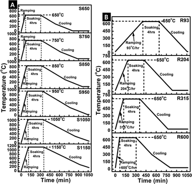
The electrospun polymer fibres were calcined in air to convert the polymer to ceramic form. The PVP polymer degrades at temperatures higher than 450 °C. In this work, the fibres were calcined using different controlled temperature heating cycles to obtain different crystalline structures: (A) rapid heating to varying soak temperatures (650, 750, 850, 950, 1050, and 1150 °C), and (B) different ramp rates (93, 204, 315, and 600 °C h−1) to the same soak temperature of 650 °C. The soak times were the same for all temperature cycles (4 h).After heating, the samples were allowed to cool slowly in the furnace. The temperature profiles for the various cycles are shown in Fig. 2. The fibre samples labelled as S650, S750, S850…S1150 correspond to the different soak temperatures and samples labelled as R93, R204, R315, and R600 correspond to the different ramp rates. As a control, the sample labelled PVP01 corresponds to uncalcined aluminium precursor – PVP fibres. The characterization and dissolution results of the fibre samples are referenced to these labels.
Physical characterization of materials
A high-resolution transmission electron microscope (HR-TEM, FEI Technai F30) operating at 300 kV and a Transmission Electron Microscope (TEM, JEM 1200XII) were used to study fibre size and morphology of the Al2O3 fibres. Small samples of the fibre mats were cut and placed in acetone, and ultrasonically vibrated to form suspensions. Drops of the suspensions were passed through a carbon coated copper grid, leaving the fibres on the grid for TEM imaging.Scanning electron microscope (SEM, FEI Quanta 200 at 30 kV and HITACHI TM300 at 15 kV) images were analysed to study the fibre morphology and determine fibre size distributions. The diameter distributions were determined from more than 100 fibre diameter measurements for each sample from the SEM images using FibraQuant 1.3 software (nanoScaffold Technologies LLC).
An X-ray diffractometer (Rigaku D/Max-2000T) with Cu anode (Kα1 = 0.154056 nm) was used for determination of the crystal phase, crystallinity, and crystal size of the Al2O3 fibres. The voltage was set to 40 kV and the current was set to 40 mA. Scans were collected with a step size of 0.1 deg and scan speed of 0.5 deg per min. The crystallite size of alumina fibres was calculated using the Scherrer equation, which relates the full width at half maxima (FWHM), W, of the most intense peak (440) of γ-Al2O3 fibre to the angle of incidence, θ, via S = cλ/W![[thin space (1/6-em)]](https://www.rsc.org/images/entities/char_2009.gif) cos
cos![[thin space (1/6-em)]](https://www.rsc.org/images/entities/char_2009.gif) θ, where S is the average crystallite size, c is the Scherrer constant and λ is the wavelength. The Scherrer constant can take values from 0.9 to 1.2, depending on the shape of the particles. Here we assumed the spherical shape (c = 1).
θ, where S is the average crystallite size, c is the Scherrer constant and λ is the wavelength. The Scherrer constant can take values from 0.9 to 1.2, depending on the shape of the particles. Here we assumed the spherical shape (c = 1).
A Fourier Transform Infrared Spectrometer (Thermo Fisher Scientific Model: Nicolet iS50 FT-IR) was used to determine the molecular bonding information of the samples. The samples were prepared by drying at 75 °C for 2 days to completely remove the moisture, and each sample was pressed into discs for the tests. The IR spectra were recorded from 400 to 4000 cm−1 at 8 cm−1 resolution.
The Brunauer, Emmett and Teller (BET) surface areas were measured using nitrogen gas adsorption (ASAP2020, Micromeritics Corp., Norcross, GA). A value of 0.162 nm2 was used for the molecular cross-sectional area of N2 at 77 K. The BET was calculated from at least six adsorption points in the range p/p0 = 0.01 to 0.3; the values were normalized by dry sample mass to calculate specific surface area with units of m2 g−1.
Powder density was measured using a helium pycnometer (AccuPycII 1340, Micromeritics) using research grade gas at 15.0 psig. Prior to the density measurements, the fibre samples were placed in an oven at 100 °C to dry overnight and allowed to cool to ambient temperature in a desiccator. A total of 25 consecutive volume measurements were made with the equilibration rate set at 0.0005 psig min−1 and the results normalized by dry sample mass to calculate density with units of g cm−3.
Artificial lung fluid dissolution studies
The biodurability of the Al2O3 fibres was assessed in two different artificial lung fluid models viz. lung airway epithelial lining fluid having near-neutral pH29 and alveolar macrophage phagolysosomal fluid having acidic pH.30 Material dissolution was evaluated using the well-established static technique.31 With this technique, a known mass of each fibre sample was weighed onto a 0.025 μm pore size 47 mm diameter nitrocellulose filter (Millipore, Bedford, MA) and a second filter of the same type was placed on top to create a ‘sandwich’. The filters served as barriers to particle migration into the dissolution medium which would bias estimates of dissolved alumina. Each filter sandwich was clamped in a dissolution chamber assembly and secured using an O-ring and Teflon screws (Fig. 3) Importantly, the filter pore size (25 nm) was significantly smaller than the diameter of the fibres.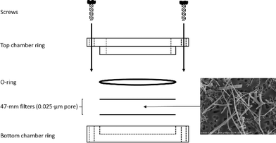 | ||
| Fig. 3 Static dissolution chamber assembly; SEM micrograph of S950 material after 7 day exposure to SUF. | ||
The fraction of each fibre sample that was aluminium metal was determined by instrumental neutron activation analysis (Elemental Analysis Inc., Lexington, KY) and used to calculate the initial mass of aluminium from the gravimetrically determined fibre masses. Each filter sandwich was secured tightly in a static dissolution chamber (Intox Products, Moriarity, nm) using four nylon screws and O-rings to provide a particle-tight seal around the edge of the sandwich. Each dissolution chamber assembly was placed in a separate plastic container with 0.080 L of lung fluid and the masses of dissolved aluminium were quantified at pre-designated time points. Triplicate dissolution chambers were prepared for each Al2O3 fibre. To mimic human lung temperature all samples were maintained at 37 °C for the duration of the respective study periods using a water-jacketed incubator.
To model the fate of particles that deposit in conducting airways, biodurability was evaluated in artificial lung airway epithelial lining fluid termed serum ultrafiltrate (SUF).29 Generally, particles that deposit in the conducting airways are bathed in the epithelial lining fluid and cleared by mucociliary action within several hours. Hence, samples of SUF were quantified for dissolved aluminium at 3 h, 6 h, 12 h, 24 h, 2 day, 4 day, and 7 day (the longer time points were collected to accurately capture the fibre dissolution kinetics). The pH of SUF was maintained at 7.3 ± 0.1 throughout the study by passing flowing CO2 (5%) and air (95%) across the solvent.
To model the fate of particles that deposit in the alveoli, biodurability was evaluated using macrophage phagolysosomal simulant fluid (PSF).30 Small particles with aerodynamic diameters below 4 μm can deposit in the distal non-ciliated alveolar (gas exchange) region of the lung. Upon deposition in the alveoli, particles are quickly engulfed by scavenger cells such as macrophages and isolated in vacuoles called lysosomes. The lysosomes merge with phagosomes that contain an acidic milieu to form phagolysosomes that function to sequester and degrade foreign materials over days to weeks. To understand dissolution kinetics over the lifespan of a macrophage cell, masses of dissolved aluminium were quantified following particle immersion for 3 h, 6 h, 12 h, 24 h, 2 day, 4 day, 7 day, 14 day, 21 day, and 28 day. The pH of PSF was maintained at 4.5 ± 0.1 using 0.02 M potassium hydrogen phthalate buffer.
Analysis of dissolved aluminium was performed using inductively coupled plasma-optical emission spectroscopy without sample digestion. The analytical limit of detection (LOD) for aluminium in SUF was 5 μg L−1 and the limit of quantification (LOQ) was 17 μg L−1. For PSF, the aluminium LOD was 10 μg L−1 and the LOQ was 43 μg L−1.
Dissolution rates of the fibres were calculated assuming constant dissolution velocity32:
 | (1) |
Free radical generation studies
Macrophages attack and engulf foreign bodies (including particles) that invade the lung where they can react with H2O2 as one of their defence mechanisms. This H2O2 can react with particles in a Fenton-like manner and generate more damaging free radicals. Modelling this respiratory burst defence system with H2O2 provides a source of preliminary data on the biological reactivity of the particles involved.33 Hence the Al2O3 fibres were reacted with H2O2 to measure their potential to generate reactive radical species when inhaled and exposed to an organism's defence systems. Hydroxyl radical production(OH−) was measured using the addition-type reaction of a short-lived radical with a compound (spin trap) to form a relatively long-lived free radical product (spin adduct), which can be studied using conventional electron spin resonance (ESR) spin trapping.For H2O2 Fenton-like reaction measurements, reactants were mixed in test tubes at a final volume of 1.0 mL of phosphate buffered saline (PBS), Al2O3 fibres in the presence of 10 mM H2O2 and 100 mM of 5,5-dimethyl-1-pyrroline-N-oxide (DMPO) (final fibre concentration of 1 mg mL−1) and vortexed for 10 seconds. In this system, a high dose was required to observe a reaction within the short exposure time necessitated by the use of ESR. The reaction mixture was transferred to a flat cell for ESR measurement (Bruker EMX spectrometer, Bruker Instruments Inc., Billerica, MA) at room temperature under ambient air. Hyperfine couplings were measured (to 0.1 G) directly from magnetic field separation using potassium tetraperoxochromate and 1,1-diphenyl-2-picrylhydrazyl as reference standards.34,35 Min–U–Sil silica (<5 μm) was used as a particle control. The relative radical concentration was estimated by multiplying half of the peak height by (ΔHpp),2 where ΔHpp represents peak-to-peak width. The Acquisit program (Bruker Instruments Inc.) was used for data acquisitions and analyses.
Results and discussion
Al2O3 fibre characterization
The unique aspect of our study design was that the correlations between dissolution and physicochemical properties of Al2O3 fibres were determined by changes in the fibre size, crystallite size, phase transformation, crystallinity, and specific surface area. These changes are important for understanding nanomaterial dissolution behaviour. Depending on the various characteristics of alumina fibres from the variations in the thermal treatments, the dissolution rates and toxicity will change.SEM, TEM, and fibre size distribution
For the analyses of the Al2O3 fibres calcined at soak temperatures 650 °C, 750 °C, 850 °C, and 950 °C for 4 h, the diameters of Al2O3 fibres gradually decreased with increase in the calcination temperature as indicated in Fig. 4 and 5 shows the different ramp rates did not have a significant effect on the fibre diameters.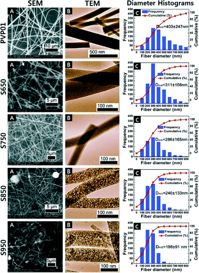 | ||
| Fig. 4 SEM (A), TEM (B) and length weighted frequency distribution of fibre size; (C) of the uncalcined fibres and the fibres calcined for 4 h at different temperatures. | ||
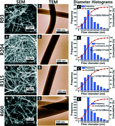 | ||
| Fig. 5 SEM (A), TEM (B) and fibre diameter distributions (C) of Al2O3 fibres calcined at 650 °C for 4 h R93 (93 °C h−1), R204 (204 °C h−1), R316 (316 °C h−1), and R600 (600 °C h−1). | ||
All of the calcined fibres had diameters smaller than the precalcined PVP polymer fibres due to evaporation of residual solvent and the degradation of the polymer. SEM and TEM images and the corresponding fibre diameter frequency distributions of the uncalcined fibres and the fibres calcined at different temperatures are shown in Fig. 4.
Each distribution of the fibre diameters was measured from at least 10 SEM images. Each histogram was generated out of 500 measurements. It is evident from the distribution plots that the distribution became narrower with calcinations at higher temperature. The S950 samples had the lowest average fibre diameter and the narrowest diameter distribution among all the materials. This trend showed that different calcination temperatures directly affected the diameters of the fibres, and is consistent with observations reported in literature.4
The TEM images in Fig. 4 show the fibres with higher calcination temperatures appear to have produced a rougher surface morphology. The apparent roughness corresponds to the increase in crystallinity of the alumina at the higher temperatures. The changes in surface structural features can be attributed to a difference in crystal formation and transformations from amorphous to γ-phase of alumina fibres (described below).
The SEM, TEM and fibre diameter distributions for R93–R600 are shown in Fig. 5. Increasing the temperature ramp rate from 93 °C per hour to 600 °C per hour appears to not have significantly changed the amorphous nature of the fibres. The smooth fibre surface shown in Fig. 5(B) indicated that there was not an obvious phase change to a crystalline structure among these samples (R93–R600) with different heating rate. The average fibre diameters were about the same and the distributions had about the same standard deviations.
XRD characterization
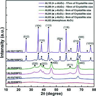
To confirm the change of the crystal structure with calcination and to correlate with the observed microscopy data, X-ray diffraction analyses were undertaken. Fig. 6 shows no crystalline peak on the samples before calcinations (PVP01) and the fibre samples calcined at soak temperature 650 °C (i.e. samples S650 and the fibres calcined at the various ramp rates R93–R600).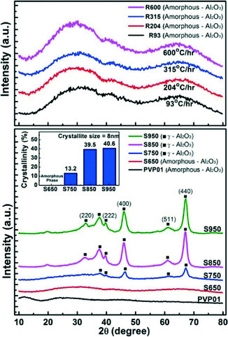 | ||
| Fig. 6 XRD patterns and crystallinity of Al2O3 fibres calcined at different soak temperatures and ramp rates. | ||
The XRD patterns of samples with calcination temperatures of 750 °C and greater (S750–S950) showed γ-phase peaks at 2θ = 32.8°, 37.6°, 39.6°, 45.9°, 61.1°, and 67.2° representing the indices of (220), (110), (222), (400), (511), and (440) crystal planes of Al2O3. The crystallinity of the samples increased with the soak temperature from 13.2% to 40.6% with 8 nm crystallite size of γ-Al2O3 fibres as displayed in Fig. 6.
FT-IR characterization
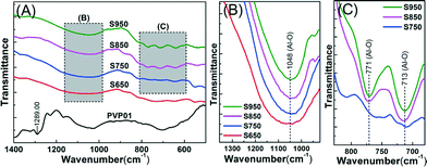
The evolution of the IR spectra of the alumina fibres with different heating conditions are shown in Fig. 7. Comparison of the precalcined PVP polymer fibre (PVP01) with the calcined fibres in Fig. 7(A) shows all of the peaks associated with the polymer aluminium acetate/PVP composite fibres (PVP01) disappeared from the spectra of the Al2O3 fibres (S650–S950). The broad and smooth absorption bands in the ranges of 400–1100 cm−1, related respectively to the Al–O (AlO6 and AlO4) and O–H stretching vibration, reveal the formation of the amorphous structure of the Al2O3 fibres, indicated in Fig. 7(B) and (C). The broad band spectra of the γ-Al2O3 observed in Fig. 7(B) is similar to that reported in literature.36–39 The absorption band of γ-Al2O3 in the range 500 to 1100 cm−1 could be related to the stretching vibration of the whole spinel unit cell.37The broad absorption at 1048 cm−1 of the samples heated at 650–950 °C indicates Al–O bond formation.39,40 With increasing calcination temperature, there was no significant increase in the intensity of the peaks. Fig. 7(C) shows that the symmetric stretching vibration AlO4 bands were located at 713 and 771 cm−1. These two stretching bands depend strongly on the crystallinity of γ-Al2O3 phase formation. Basically, the cation vacancy distribution leads to the appearance of the broad band due to disordered vacancies. It means that the formation of peaks at 713 and 771 cm−1 are associated with the larger lattice distortion.37,41 Comparing intensity of the adsorption bands of samples S750, S850 and S950 in Fig. 7(C), shows the γ-Al2O3 was formed with increasing calcinations temperature.
BET, INAA and helium pycnometry characterization
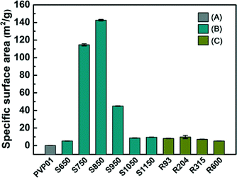
Fig. 8 shows the specific surface areas for all of the samples. The specific surface areas increased up to soak temperature 850 °C followed by a decrease in area at soak temperature 950 °C. To determine if the decline in surface area continued at higher temperatures, additional samples were calcined at temperatures 1050 and 1150 °C (S1050 and S1150). The surface areas of the additional samples plateaued at about 16 g m−2. Samples calcined at the different ramp rates to the same soak temperature (R93–R600) did not show significant change in the specific surface area, indicating the soak temperature is the more important factor.BET and XRD characterization were performed to comprehend the correlation between the reduction of surface area and crystal structure. Generally, during the transition from γ- to α-Al2O3 crystal phases, a dramatic reduction in surface area occurs.42,43 Upon heating, the γ-Al2O3 goes through a series of transformations to reach the thermodynamically stable α-Al2O3 phase structure.42,44,45 Thus, the surface grain coarsening of the Al2O3 fibre incurred during calcination can lead to reduction of the specific surface area.44
Fig. 9 shows that alumina fibres calcined at 1050 °C (S1050) and 1150 °C (S1150) had alpha crystal structures with 15 nm and 17 nm of estimated crystallite sizes. The increase in peak intensities with increase in temperature shows the progressive increase in the alpha phase content of the fibres and the coalescence of the tiny crystallites started accelerating the grain growth to go to alpha phase. From XRD and TEM studies, crystallite growth was also demonstrated by the increase of calcinations temperature, which may reveal how phase transformation modified the fibre morphology and crystal structure.
Fig. 10 shows the atomic alumina content and fibre intrinsic density of the fibres. Within the error of the measurements (relative standard deviation = 6%), the Al content of S950, R204, and R315 matched the value expected from stoichiometry of Al2O3 (52.9%). The calcination temperature clearly made a difference in Al content from PVP01 to S950 in Fig. 10(top). However, regardless of ramp rate, samples R93 to R315 had similar (but slightly less than theoretical) Al content apart from R600 samples. Al content of R600 was approximately 40%. In Fig. 10(bottom), the density of the samples also increased with calcination temperature, which was also related to agglomerated grains on the surface of the alumina fibres calcined at high temperature. Density of R93, R204…R600 samples having different ramping rate had no significant change of the values.
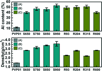 | ||
| Fig. 10 Al content (top) and density of alumina fibre (bottom) (A) PVP01, (B) S650–S950, and (C) R93–R600. | ||
Artificial lung fluid dissolution studies
On a mass basis, the total amounts of aluminium dissolved from the fibres ranged from 0.2 to 13.5% in SUF (Table 1) and from 0.5 to 36% in PSF (Table 2). In both lung fluid models, the largest total masses of dissolved aluminium were from the uncalcined PVP01 material, which reflects the greater solubility of the precursor aluminium acetate relative to the heat-treated alumina fibres.| Dissolution parameters (mean ± standard deviation) | |||||
|---|---|---|---|---|---|
| Initial rapid phase | Latter long-term phase | ||||
| Material | Dissolved (%) | t 1/2 (days) | k (g per cm2 per day) | t 1/2 (days) | k (g per cm2 per day) |
| a S650 is the same as R600. | |||||
| PVP01 | 13.48 ± 6.66 | 9 ± 3 | 5.6 ± 2.0 × 10⁻⁵ | 125 ± 57 | 4.4 ± 2.3 × 10⁻⁶ |
| S650a | 1.13 ± 0.07 | 1032 ± 484 | 1.5 ± 0.7 × 10⁻⁸ | 1764 ± 185 | 7.5 ± 0.8 × 10⁻⁹ |
| S750 | 0.56 ± 0.13 | 1343 ± 385 | 4.8 ± 1.6 × 10⁻¹⁰ | 3480 ± 520 | 1.8 ± 0.3 × 10⁻¹⁰ |
| S850 | 0.36 ± 0.11 | 1689 ± 195 | 2.9 ± 0.3 × 10⁻¹⁰ | 5515 ± 1223 | 1.0 ± 0.0 × 10⁻¹⁰ |
| S950 | 0.22 ± 0.07 | 4761 ± 2573 | 3.9 ± 1.9 × 10⁻¹⁰ | 9881 ± 3394 | 1.7 ± 0.7 × 10⁻¹⁰ |
| R93 | 0.29 ± 0.10 | 4058 ± 1553 | 2.1 ± 0.7 × 10⁻⁹ | 6998 ± 2461 | 1.2 ± 0.4 × 10⁻⁹ |
| R204 | 0.30 ± 0.03 | 5874 ± 852 | 1.2 ± 0.2 × 10⁻⁹ | 5387 ± 1080 | 1.4 ± 0.3 × 10⁻⁹ |
| R315 | 0.49 ± 0.13 | 4933 ± 1880 | 1.9 ± 0.6 × 10⁻⁹ | 4164 ± 1009 | 2.1 ± 0.5 × 10⁻⁹ |
| R600 | 1.13 ± 0.07 | 1032 ± 484 | 1.5 ± 0.7 × 10⁻⁸ | 1764 ± 185 | 7.5 ± 0.8 × 10⁻⁹ |
| Dissolution parameters (mean ± standard deviation) | |||||
|---|---|---|---|---|---|
| Initial rapid phase | Latter long-term phase | ||||
| a S650 is the same as R600. | |||||
| Material | Dissolved (%) | t 1/2 (Days) | k (g per cm2 per day) | t 1/2 (days) | k (g per cm2 per day) |
| PVP01 | 35.93 ± 4.05 | 13 ± 2 | 3.7 ± 0.6 × 10⁻⁵ | 147 ± 18 | 3.2 ± 0.4 × 10⁻⁶ |
| S650a | 3.29 ± 0.47 | 337 ± 36 | 3.9 ± 0.4 × 10⁻⁸ | 1958 ± 302 | 6.8 ± 1.0 × 10⁻⁹ |
| S750 | 2.16 ± 0.13 | 390 ± 50 | 1.6 ± 0.2 × 10⁻⁹ | 2897 ± 201 | 2.1 ± 0.1 × 10⁻¹⁰ |
| S850 | 2.08 ± 0.69 | 493 ± 221 | 1.1 ± 0.5 × 10⁻⁹ | 3215 ± 1004 | 1.6 ± 0.6 × 10⁻¹⁰ |
| S950 | 1.18 ± 0.18 | 925 ± 328 | 1.8 ± 0.6 × 10⁻⁹ | 5496 ± 961 | 2.9 ± 0.5 × 10⁻¹⁰ |
| R93 | 0.47 ± 0.15 | 4330 ± 2443 | 2.3 ± 1.4 × 10⁻⁹ | 16![[thin space (1/6-em)]](https://www.rsc.org/images/entities/char_2009.gif) 365 ± 5639 365 ± 5639 |
5.3 ± 2.0 × 10⁻¹⁰ |
| R204 | 0.48 ± 0.20 | 4294 ± 1119 | 1.8 ± 0.5 × 10⁻⁹ | 16![[thin space (1/6-em)]](https://www.rsc.org/images/entities/char_2009.gif) 943 ± 8692 943 ± 8692 |
4.9 ± 2.0 × 10⁻¹⁰ |
| R315 | 0.47 ± 0.13 | 3658 ± 99 | 2.3 ± 0.1 × 10⁻⁹ | 15![[thin space (1/6-em)]](https://www.rsc.org/images/entities/char_2009.gif) 609 ± 4110 609 ± 4110 |
5.7 ± 1.4 × 10⁻¹⁰ |
| R600 | 3.29 ± 0.47 | 337 ± 36 | 3.9 ± 0.4 × 10⁻⁸ | 1958 ± 302 | 6.8 ± 1.0 × 10⁻⁹ |
Aluminium dissolution was biphasic in both lung fluid models. Estimates of the dissolution half-time, t1/2 (the time to clear half the mass via solubilization) and the chemical dissolution rate constant (k) for the initial rapid phase and latter long-term phase of each Al2O3 fibre are summarized in Table 1 (SUF) and in Table 2 (PSF). In both SUF and PSF, k values for PVP01 were significantly faster than all of the alumina fibres (p < 0.05).
Inhaled alumina fibres that deposit in the conducting airways will be subject to clearance via chemical dissolution and mechanical action (mucociliary-mediated transport). Particle clearance by chemical dissolution depends upon the composition of the airway lining fluid, chemistry of the particle, etc. In contrast, mechanical clearance is independent of these factors and transport to the pharynx (where the particles are swallowed and excreted via the gastrointestinal tract) occurs at rapid rates with half-times of approximately 2 to 8 h.46
Hence, for SUF, the calculated t1/2 and k values indicate that if Al2O3 fibres deposit in the conducting airways of the lung, little material will dissolve prior to removal by mechanical action.
Once deposited in the non-ciliated alveolar (gas exchange) region of the lung, particles are rapidly engulfed by AM and sequestered within phagolysosomes. The engulfed particles are cleared via chemical dissolution in the acidic microenvironment of the phagolysosomes and by movement of particle-laden cells to the ciliated bronchioles,19 and eventually to the pharynx. Movement of AM to the ciliated bronchioles is a very slow process with half-times of approximately 35 to 7000 days.46
Generally, the initial and latter phase dissolution half-times of the alumina fibres in PSF were less than 7000 days. The greater solubility of alumina fibres in PSF relative to macrophage-mediated clearance indicates that chemical dissolution is an important clearance mechanism if these fibres were to deposit in the alveoli.
The exception to this observation was the latter-phase dissolution half-times for R93, R204, and R315 which were a factor of two longer than expected for mechanical clearance and would be expected to have prolonged persistence in the alveoli. The slow dissolution and potential persistence of aluminium oxide fibres in the lung alveoli has important implications for understanding human health. Released ions can bind to proteins such as albumin and/or be eliminated through urine. Persistence of particulate can induce pulmonary damage as a consequence of accumulation of non-reactive particles.47 Aluminium is ubiquitous in our environment and is present in trace amounts in the human body, as such, inhalation and dissolution of aluminium particulate could lead to biomagnification of levels in the body and alter homeostasis.
There were no statistical differences in the initial rapid or latter long-term dissolution rates among S650 (650 °C), S750 (750 °C), S850 (850 °C), and S950 (950 °C) in either SUF or PSF. Hence, our data indicate that dissolution rates were independent of calcination temperature. Next, we evaluated the influence of calcination ramp rate on dissolution using the fibres that were calcined at the same temperature (650 °C) but using heating ramp rates of 93 (R93), 204 (R204), 315 (R315) or 600 (R600) °C per hour.
The dissolution clearance half-time of R600 was significantly shorter compared to R93, R204, and R315 (p < 0.05). The long term dissolution rates of aluminium from R600 were a factor of five faster in SUF and a factor of 14 faster in PSF relative to R93–R315, though differences were not significant. These data suggest an effect of calcination ramp rate on dissolution (all four types had similar diameters and densities and were amorphous). Specifically, a rapid ramp rate (600 °C per hour) to 650 °C yielded a less persistent alumina fibre. For a metallurgical study regarding the effect of ramp rate, some authors showed that densification and fine grain sizes of alumina materials could be changed.48–50
There have been conflicting results. Stanciu et al. and Zhou et al. reported that the grain size of alumina decreased with increasing heating rate under 45 MPa pressure and high densities was obtained in alumina ceramic materials without any additives.48,49 Whereas, Kim et al. stated that the grain size and residual porosity decreased with slow heating rate.50 Hence, heating ramp rate might affect dissolution results due to the change of the densification and the direct grain to grain contact at molecular scale in alumina ceramic fibre.
Previously, Adamcakova-Dodd et al. evaluated the dissolution of a commercially available Al2O3 fibre material using a model of airway epithelial lining fluid and a model of macrophage lysosomal fluid analogous to SUF and PSF, respectively.26 Though sold as Al2O3 powder, characterization of the as-received material revealed that it was primarily composed of crystalline aluminium hydroxide. The authors reported that the dissolution of aluminium hydroxide was generally linear in both lung fluid models. From their data, we estimated that k = 9 × 10⁻¹⁰ g per cm2 per day in their airway lining fluid model and k = 4 × 10⁻⁹ g per cm2 per day in their macrophage lysosomal fluid. Our k value estimates for the long-term dissolution of amorphous (with the exception of PVP01, S650, and R600) and crystalline alumina fibres were similar to that derived for aluminium hydroxide.
Visual inspection of Al2O3 fibres after 28 days of exposure to PSF indicated that these materials were susceptible to transverse breakage (Fig. 11). For macrophages to be effective in removing fibres from the alveoli, the fibres should be completely engulfed by the cells. If the fibres are too long, mechanical clearance via particle-laden macrophage migration from the alveoli is less effective. Our observation that the Al2O3 fibres break transversely from exposure to PSF is important because breakage transforms long fibres into shorter fibres which are more easily cleared by AMs via migration from the alveoli.13
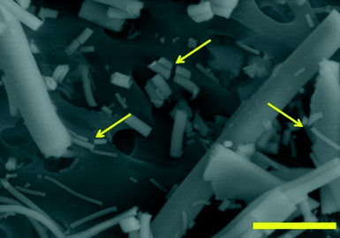 | ||
| Fig. 11 Scanning electron micrograph of alumina fibre S950 (950 °C) illustrating transverse fibre breakage (see arrows) after exposure to PSF for 28 days. Scalebar = 1 μm. | ||
Free radical generation
None of the Al2O3 fibres generated measureable levels of ˙OH radicals in the cell-free H2O2 test system. Both of the soluble hexavalent chromium and particulate silica positive control samples generated high levels of hydroxyl radicals. The absence of radical production by these Al2O3 fibres is consistent with Adamcakova-Dodd et al. who reported that inhalation of aluminium hydroxide whiskers by mice did not produce lung inflammation.26It is important to note that macrophage engulfment of particles and reaction with H2O2 was screened using a cell-free system. In cellular systems, particle size, shape, and/or surface charge influence uptake by cells.20–23 For example, titanium dioxide nanobelts having length of <5 μm are fully taken up into cell lysosomes whereas longer nanobelts with length >15 μm are only partially internalized with the rest sticking out into the cytoplasm.23 Depending on their degree of internalization and interaction with organelles, particulate can promote various biological responses, including cell proliferation, free radical generation, release of pro-inflammatory cytokines, cytotoxicity, apoptosis, cytoskeleton formation, and adhesion and migration.
Conclusions
The present study concluded the biodurability of eight electrospun alumina fibre modified by different heating protocol in artificial lung fluid models. We found that first, uncalcined PVP-Al2O3 fibre (PVP01) was significantly faster than all other alumina fibres, and alumina fibres calcined from 650 °C to 950 °C (S650–S950) did not cause the change of dissolution half-time significantly. Thus, the physicochemical property of Al2O3 fibre had no effect on dissolution behaviour in either SUF or PSF. For the variation in heating ramp rate (R93–R600), the alumina fibres from R600 had a significantly greater dissolution rate compared to slowly heated alumina fibre samples (R93–R315) even though these four samples had similar physicochemical property such as, fibre diameter, crystal structure (amorphous), surface area, and density. The fibres with increased solubility have a reduced inflammogenic potential. To fully understand the effect of the ramping rate, additional work is needed.Acknowledgements
This work was financially supported by the Coalescence Filtration Nanofibres Consortium: Donaldson, Ahlstrom, Parker Hannifin, Cummins Filtration, Bekaert, Hollingsworth and Vose, and SNS Nanofibre Technology to fabricate the fibres. H. U. Shin specially thanks Youlee Hong, Jeongwoo lee and Sangyoup Hwang for their technical assistance with TEM and FT-IR analysis. A. B. Stefaniak wishes to acknowledge M. G. Duling and R. B. Lawrence for their technical support with the dissolution studies and Dr. M. A. Virji for guidance on statistics. Mention of a specific product or company does not constitute endorsement by the Centers for Disease Control and Prevention. The findings and conclusions in this report are those of the authors and do not necessarily represent the views of NIOSH. N.S. was supported by UWO FDR859 grant.Notes and references
- T. Lin, Nanofibres: Production, properties and functional applications, InTech, 2011 Search PubMed.
- R. Ramaseshan, S. Sundarrajan, R. Jose and S. Ramakrishna, J. Appl. Phys., 2007, 102, 111101–111117 CrossRef.
- H. U. Shin, Y. Li, A. Paynter, K. Nartetamrongutt and G. G. Chase, Polymer, 2015, 65, 26–33 CrossRef CAS.
- S. J. Park, S. Bhargava, E. T. Bender, G. G. Chase and R. D. Ramsier, J. Mater. Res., 2008, 23, 1193–1196 CrossRef CAS.
- R. S. Barhate, C. K. Loong and S. Ramakrishna, J. Membr. Sci., 2006, 283, 209–218 CrossRef CAS.
- R. C. Brown, Air filtration: an integrated approach to the theory and applications of fibrous filters, Pergamon Press, 1993 Search PubMed.
- K. Graham, M. Ouyang, T. Raether, T. Grafe, B. McDonald and P. Knauf, Fifteenth Annual Technical Conference & Expo of the American Filtration & Separations Society, 2002, pp. 9–12 Search PubMed.
- National Research Council of the National Academies, A Research Strategy for Environmental, Health, and Safety Aspects of Engineered Nanomaterials, The National Academies Press, 2012 Search PubMed.
- S. K. Misra, A. Dybowska, D. Berhanu, S. N. Luoma and E. Valsami-Jones, Sci. Total Environ., 2012, 438, 225–232 CrossRef CAS PubMed.
- H. Braakhuis, M. Park, I. Gosens, W. De Jong and F. Cassee, Part. Fibre Toxicol., 2014, 11(18), 1–25 Search PubMed.
- P. Borm, F. C. Klaessig, T. D. Landry, B. Moudgil, J. Pauluhn, K. Thomas, R. Trottier and S. Wood, Toxicol. Sci., 2006, 90, 23–32 CrossRef CAS PubMed.
- R. Landsiedel, L. Ma-Hock, A. Kroll, D. Hahn, J. Schnekenburger, K. Wiench and W. Wohlleben, Adv. Mater., 2010, 22, 2601–2627 CrossRef CAS PubMed.
- K. Donaldson, F. Murphy, A. Schinwald, R. Duffin and C. A. Poland, Nanomedicine, 2010, 6, 143–156 CrossRef PubMed.
- J. M. G. Davis, Environ. Health Perspect., 1994, 102, 113–117 CrossRef CAS PubMed.
- R. O. McClellan and T. W. Hesterberg, Environ. Health Perspect., 1994, 102, 277–283 CrossRef PubMed.
- T. W. Hesterberg and G. A. Hart, Crit. Rev. Toxicol., 2001, 31, 1–53 CrossRef CAS PubMed.
- L. D. Maxim, J. G. Hadley, R. M. Potter and R. Niebo, Regul. Toxicol. Pharmacol., 2006, 46, 42–62 CrossRef CAS PubMed.
- A. Stefaniak, Part. Fibre Toxicol., 2010, 7(38), 1–9 Search PubMed.
- D. Bernstein, V. Castranova, K. Donaldson, B. Fubini, J. Hadley, T. Hesterberg, A. Kane, D. Lai, E. E. McConnell, H. Muhle, G. Oberdorster, S. Olin and D. B. Warheit, Inhalation Toxicol., 2005, 17, 497–537 CrossRef CAS PubMed.
- S. K. Misra, S. Nuseibeh, A. Dybowska, D. Berhanu, T. D. Tetley and E. Valsami-Jones, Nanotoxicology, 2014, 8, 422–432 CrossRef CAS PubMed.
- S. E. A. Gratton, P. A. Ropp, P. D. Pohlhaus, J. C. Luft, V. J. Madden, M. E. Napier and J. M. DeSimone, Proc. Natl. Acad. Sci. U. S. A., 2008, 105, 11613–11618 CrossRef CAS PubMed.
- X. Huang, X. Teng, D. Chen, F. Tang and J. He, Biomaterials, 2010, 31, 438–448 CrossRef CAS PubMed.
- R. Hamilton, N. Wu, D. Porter, M. Buford, M. Wolfarth and A. Holian, Part. Fibre Toxicol., 2009, 6(35), 1–11 Search PubMed.
- I. L. Hsiao and Y.-J. Huang, Sci. Total Environ., 2011, 409, 1219–1228 CrossRef CAS PubMed.
- Q. Mu, C. A. David, J. Galceran, C. Rey-Castro, Ł. Krzemiński, R. Wallace, F. Bamiduro, S. J. Milne, N. S. Hondow, R. Brydson, G. Vizcay-Barrena, M. N. Routledge, L. J. C. Jeuken and A. P. Brown, Chem. Res. Toxicol., 2014, 27, 558–567 CrossRef CAS PubMed.
- A. Adamcakova-Dodd, L. Stebounova, P. O'Shaughnessy, J. Kim, V. Grassian and P. Thorne, Part. Fibre Toxicol., 2012, 9(22), 1–14 Search PubMed.
- J. S. Varabhas, G. G. Chase and D. H. Reneker, Polymer, 2008, 49, 4226–4229 CrossRef CAS.
- D. H. Reneker, A. L. Yarin, H. Fong and S. Koombhongse, J. Appl. Phys., 2000, 87, 4531–4547 CrossRef CAS.
- G. L. Finch, J. A. Mewhinney, A. F. Eidson, M. D. Hoover and S. J. Rothenberg, J. Aerosol Sci., 1988, 19, 333–342 CrossRef CAS.
- A. B. Stefaniak, R. A. Guilmette, G. A. Day, M. D. Hoover, P. N. Breysse and R. C. Scripsick, Toxicol. in vitro, 2005, 19, 123–134 CrossRef CAS PubMed.
- G. M. Kanapilly, O. G. Raabe, C. H. T. Goh and R. A. Chimenti, Health Phys., 1973, 24, 497–507 CrossRef CAS.
- R. M. Potter and S. M. Mattson, Glastech. Ber., 1991, 64, 16–28 CAS.
- C. Dahlgren, A. Karlsson and J. Bylund, in Neutrophil Methods and Protocols, ed. M. Quinn, F. DeLeo and G. Bokoch, Humana Press, 2007, ch. 23, vol. 412, pp. 349–363 Search PubMed.
- E. G. Janzen and B. J. Blackburn, J. Am. Chem. Soc., 1968, 90, 5909–5910 CrossRef CAS.
- G. R. Buettner, Free Radical Biol. Med., 1987, 3, 259–303 CrossRef CAS PubMed.
- P. Tarte, Spectrochim. Acta, Part A, 1967, 23, 2127–2143 CrossRef CAS.
- J. Saniger, Mater. Lett., 1995, 22, 109–113 CrossRef CAS.
- C. Pecharromán, I. Sobrados, J. E. Iglesias, T. González-Carreño and J. Sanz, J. Phys. Chem. B, 1999, 103, 6160–6170 CrossRef.
- X. Du, Y. Wang, X. Su and J. Li, Powder Technol., 2009, 192, 40–46 CrossRef CAS.
- T. Meher, A. K. Basu and S. Ghatak, Ceram. Int., 2005, 31, 831–838 CrossRef CAS.
- C. Mo, Z. Yuan, L. Zhang and C. Xie, Nanostruct. Mater., 1993, 2, 47–54 CrossRef CAS.
- R. N. Das, A. Hattori and K. Okada, Appl. Catal., A, 2001, 207, 95–102 CrossRef CAS.
- J. H. Kwak, C. H. F. Peden and J. N. Szanyi, J. Phys. Chem. B, 2011, 115, 12575–12579 CAS.
- I. Levin and D. Brandon, J. Am. Ceram. Soc., 1998, 81, 1995–2012 CrossRef CAS.
- P.-C. Yu, R.-J. Yang, Y.-Y. Tsai, W. Sigmund and F.-S. Yen, J. Eur. Ceram. Soc., 2011, 31, 723–731 CrossRef CAS.
- ICRP, Human Respiratory Tract Model for Radiological Protection, ICRP Publication 66, 1994 Search PubMed.
- C. C. Willhite, N. A. Karyakina, R. A. Yokel, N. Yenugadhati, T. M. Wisniewski, I. M. F. Arnold, F. Momoli and D. Krewski, Crit. Rev. Toxicol., 2014, 44, 1–80 CrossRef CAS PubMed.
- Y. Zhou, K. Hirao, Y. Yamauchi and S. Kanzaki, J. Eur. Ceram. Soc., 2004, 24, 3465–3470 CrossRef CAS.
- L. A. Stanciu, V. Y. Kodash and J. R. Groza, Metall. Mater. Trans. A, 2001, 32, 2633–2638 CrossRef.
- B.-N. Kim, K. Hiraga, K. Morita and H. Yoshida, J. Eur. Ceram. Soc., 2009, 29, 323–327 CrossRef CAS.
| This journal is © The Royal Society of Chemistry 2015 |


