
 Open Access Article
 This Open Access Article is licensed under a Creative Commons Attribution-Non Commercial 3.0 Unported Licence
Photoinduced charge transfer processes in solar photocatalysis based on modified TiO2
Hyunwoong
Park
a,
Hyoung-il
Kim
b,
Gun-hee
Moon
b and
Wonyong
Choi
*b
aSchool of Energy Engineering, Kyungpook National University, Daegu 702-701, Korea
bSchool of Environmental Science and Engineering, Pohang University of Science and Technology (POSTECH), Pohang 790-784, Korea. E-mail: wchoi@postech.edu; Tel: +82-54-279-2283
First published on 1st December 2015
Abstract
High efficiency solar photocatalysis requires an effective separation of photogenerated charge carriers and their rapid transport to the semiconductor interface. The mechanisms and kinetics of charge separation and interfacial/interparticle charge transfers (CT) are significantly influenced by both the bulk and surface properties of the semiconductor. The surface properties are particularly important because the photocatalysis should be driven by the interfacial CT. The most popular and the most investigated semiconductor photocatalyst is based on bare and modified TiO2. This article highlights the interfacial and interparticle CTs under the bandgap excitation of TiO2 particles, visible light-induced photochemical processes via either dye-sensitization or ligand-to-metal CTs at surface modified TiO2 particles, and the applications of the photo-processes to pollutant degradation and simultaneous hydrogen production. While a variety of surface modification techniques using various nanomaterials and chemical reagents have been developed and tested so far, their effects are very diverse depending on the characteristics of the applied photocatalytic systems and even contradictory in some cases. Better understanding of how the modification influences the photoinduced CT events in semiconductors is required, particularly for designing hybrid photocatalysts with controlled CTs, which is sought-after for practical applications of photocatalysis.
 Hyunwoong Park | Hyunwoong Park received a BS in Environmental Science at Hallym University in 1999 and a PhD degree (advisor: Wonyong Choi) in Environmental Engineering at POSTECH (Pohang, Korea) in 2004. After postdoctoral research at the California Institute of Technology (Pasadena, California: 2006–2008), he moved to the School of Energy Engineering at Kyungpook National University (Daegu, Korea) as an assistant professor (2008) and was then promoted to associate professor (2012). He has published over 80 papers in peer-reviewed journals, which have been cited over 4500 times. He was awarded the Knowledge Creativity Award by the Ministry of Education, Science, and Technology, Korea (2012), and the Best Paper Award by the Korean Electrochemical Society (2013). He is serving as the Editor of Materials Science in Semiconductor Processing (Elsevier, since 2015) and the Associate Editor of Environmental Engineering Research (Korean Society of Environmental Engineers, since 2014). He is also on the editorial advisory boards of Journal of Environmental Chemical Engineering (Elsevier, since 2013) and International Journal of Photoenergy (Hindawi, since 2014). |
 Hyoung-il Kim | Hyoungil Kim received a BS in Environmental Engineering at Inha University (Incheon, Korea) in 2008 and a PhD degree (advisor: Wonyong Choi) in Environmental Engineering at POSTECH (Pohang, Korea) in 2014. He spent a half year at POSTECH as a postdoctoral researcher and is currently working in Chemical and Environmental Engineering at Yale University (New Haven, U.S.A.) as a postdoctoral researcher. |
 Gun-hee Moon | Gun-hee Moon received a BS in Chemical Engineering at Inha University (Incheon, Korea) in 2008, an MS degree in Environmental Engineering from POSTECH in 2011, and a PhD degree (advisor: Wonyong Choi) in Chemical Engineering from POSTECH (Pohang, Korea) in 2015. He joined the Materials Science Division of Pacific Northwest National Laboratory (Richland, Washington) as an Alternate Sponsored Fellowship (2011–2012). He is currently working as a postdoctoral researcher in Prof. Choi's laboratory. |
 Wonyong Choi | Wonyong Choi received a BS in engineering from Seoul National University (Seoul, Korea) in 1988, an MS in chemistry from POSTECH in 1990, and a PhD in chemistry from California Institute of Technology in 1996. After postdoctoral research in atmospheric chemistry at NASA/Caltech Jet Propulsion Laboratory (1996–1998), he joined the faculty of School of Environmental Science and Engineering, POSTECH as an assistant professor (1998), and was promoted to associate professor (2003), and full professor (2008). His research interests are mainly focused on semiconductor photocatalysis and photochemistry for solar energy conversion and environmental applications, advanced oxidation processes, and environmental chemistry. He has published over 230 papers in peer-reviewed journals, which have been cited over 23 |
![[thin space (1/6-em)]](https://www.rsc.org/images/entities/char_2009.gif) 000 times (H-index 60, Web of Science) to date. He received the Young Scientist Award (2006) and the KAST Science and Technology Award (2015) from the Korean Academy of Science and Technology (KAST), Lectureship Award from the Japanese Photochemistry Association (2008), Rising Star faculty fund from POSTECH (2011), Namgo chair professorship from POSTECH (2012) and was elected as Fellow of KAST and Fellow of Royal Society of Chemistry (FRSC) in 2014. Currently, he is serving as the Editor of Journal of Hazardous Materials (Elsevier, 2008–). He has been also on the editorial advisory boards of Energy and Environmental Science (RSC, 2008–), Environmental Science and Technology (ACS, 2015–), and Journal of Physical Chemistry (ACS, 2009–2011).
000 times (H-index 60, Web of Science) to date. He received the Young Scientist Award (2006) and the KAST Science and Technology Award (2015) from the Korean Academy of Science and Technology (KAST), Lectureship Award from the Japanese Photochemistry Association (2008), Rising Star faculty fund from POSTECH (2011), Namgo chair professorship from POSTECH (2012) and was elected as Fellow of KAST and Fellow of Royal Society of Chemistry (FRSC) in 2014. Currently, he is serving as the Editor of Journal of Hazardous Materials (Elsevier, 2008–). He has been also on the editorial advisory boards of Energy and Environmental Science (RSC, 2008–), Environmental Science and Technology (ACS, 2015–), and Journal of Physical Chemistry (ACS, 2009–2011).
Broader contextPhotocatalysis based on semiconductor materials is being actively investigated as a core technology in solar light harvesting and utilizing processes. The basic process is driven by the photoinduced charge transfers (CTs) occurring on the irradiated semiconductor surface with initiating various redox reactions that are utilized for environmental remediation and solar energy storage. The former reaction is usually initiated by a single electron transfer under aerated conditions to generate reactive oxygen species whereas the latter proceeds via two or more electron transfers in the absence of molecular oxygen. Most of the former reaction systems are thermochemically spontaneous (ΔG° < 0) and lead to the mineralization of organic pollutants whereas the latter is an energy uphill process (ΔG° > 0) and often needs co-catalysts to facilitate the multi-electron transfer processes. The mechanisms and kinetics of interfacial/interparticle CTs are influenced by the bulk and surface properties of semiconductor. While various surface modification techniques have been developed so far, their effects are very diverse and even contradictory in some cases. Better understanding of how the modification influences the photoinduced CT events in semiconductors is required, particularly for designing hybrid photocatalysts with controlled CTs, which is sought-after for practical applications of photocatalysis. |
1. Introduction
Solar energy is the main driver of most biological and global environmental processes. In addition, the need of harvesting and utilizing sunlight as a renewable source of energy is continuously increasing. Solar photocatalysis based on semiconductor materials has been extensively studied over the past four decades and is still being actively investigated as a core technology in solar light harvesting and solar conversion processes.1–11 The basic process is driven by the photoinduced charge transfers occurring on the irradiated semiconductor surface with initiation of a variety of redox conversion reactions. Most of the semiconductor photocatalytic processes have been studied for the production of solar fuels (e.g., H2) and for the environmental purification of contaminated water and air.2–9 As the cost of fossil fuels and the demand for advanced environmental remediation technologies increase, the fundamental studies on photocatalysis12–16 as well as its practical applications6,17 have received growing attention.18 A bibliographic database web-engine (Scopus) search finds over 7500 and 3500 publications in 2014 alone for the search keywords of photocatal* and TiO2* photocatal*, respectively, which reflects the continued popularity of this research field.A variety of semiconductor photocatalysts (TiO2,4,5,7,8,10,19 ZnO,20–22 WO3,23–27 Fe2O3,28 BiVO4,29–31 CdS,25,32–34 CdSe,35etc.) with different morphologies and modifications have been studied and developed. Photocatalysis is initiated by the light absorption by the semiconductor, followed by the charge-pair separation and interfacial charge transfer (CT). Since these reactions primarily occur on the surface, the modifications of semiconductor surface structures and properties significantly influence the overall photocatalytic reaction kinetics and mechanisms.7,8 The imbalance of the interfacial CT of electrons and holes causes the charge pairs to rapidly recombine with each other, reducing or even nullifying the overall photocatalytic activity of interest. In this regard, proper understanding of the behavior of photogenerated CTs is necessary to achieve the desired reactions with high efficiency. With advancements in the fundamental studies on charge carrier dynamics,16 the behaviors of photogenerated charge carriers have been more clearly elucidated. This helps us to understand how surface modification affects the photocatalytic processes in different ways, and eventually controls the photocatalytic pathways and activity.
The CT reactions occurring on semiconductor photocatalysts have been applied for two main purposes: (1) environmental applications for the remediation of polluted water and air and (2) solar energy storage through the synthesis of solar fuels (e.g., H2 production from water splitting, CO2 conversion to hydrocarbons). Scheme 1 illustrates how the characteristics of CTs in the two processes are different. The former process is usually initiated by a single electron transfer under aerated conditions to generate reactive radical species, whereas the latter proceeds via two or more electron transfers in the absence of molecular oxygen (O2). Generally, the photocatalytic degradation of organic compounds does not proceed in the absence of O2, whereas the photocatalytic production of solar fuels (e.g., H2, HCOOH) is very difficult to be achieved in the presence of O2 because the molecular oxygen scavenges photogenerated electrons.36 Most of the former reaction systems are thermochemically spontaneous (ΔG° < 0) and lead to the mineralization of organic pollutants, whereas the latter for solar fuel synthesis is an energy uphill (energy-storing) process (ΔG° > 0) and often needs co-catalysts (e.g., Pt,37 Pd,38 Co,29,39,40 Ni,41,42 Sn,43 and Mn44) to facilitate the multi-electron transfer processes.
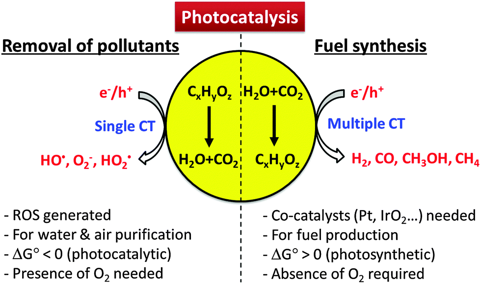 | ||
| Scheme 1 Comparison of photocatalytic reaction features for environmental purification versus solar fuel synthesis. | ||
Some outstanding questions related to CT on semiconductor photocatalysts are as follows: (1) How can the recombination of charge pairs be minimized? (2) How can the single-electron transfer and the multi-electron transfer processes be controlled? (3) What determines the pathways of hole (or electron) transfer reactions leading to the generation of reactive radical species such as hydroxyl radical, superoxide, or singlet oxygen? Is it possible to control this selectively and if so, how? (4) How can visible light photons be utilized to induce CT in semiconductor photocatalysis? Such questions and the related research topics are listed as examples in Table 1. With these in mind, this article discusses the photoinduced CT occurring on semiconductor photocatalysts modified with various methods developed by this research group and addresses the above questions.
| Questions | Related topics | Research examples |
|---|---|---|
| How can the recombination of charge pairs be minimized? | Metal deposition | 23, 37, 98, 114, 241 |
| Composites with carbon nanomaterials | 33, 35, 145, 149, 242 | |
| Doping (metals & non-metals) | 28, 53, 54, 56, 57, 243–245 | |
| Electron shuttle | 37, 85, 95 | |
| Interparticle CT systems | 160–163, 166 | |
| Heterojunctions (binary, tertiary, etc.) | 25, 26, 32 | |
| How can multi-electron transfer processes be facilitated? | Catalysts for hydrogen evolution | 33, 35, 80, 98, 145, 149, 246, 247 |
| Catalysts for oxygen evolution | 20, 28, 29, 45 | |
| Catalysts for CO2 conversion | 139, 154, 248 | |
| Catalysts for H2O2 production | 82, 249 | |
| What influences the charge transfer reactions that lead to the generation of reactive oxygen species? Is it possible to control this selectively? | Fluorination | 75, 77, 79, 80, 250 |
| Phosphonation | 76, 80 | |
| Ion exchange resin | 61, 154, 215 | |
| Surfactants | 223, 251 | |
| Polymers | 72, 211 | |
| Structural engineering (porosity, surface area, nanostructure, etc.) | 163, 164, 166, 252 | |
| How can visible light photons be utilized to induce CT in photocatalytic systems? | Doping | 53, 54, 56, 57, 243–245 |
| Dye sensitization | 97, 98, 104, 166, 201, 207, 213–217 | |
| Ligand-to-metal charge transfer (LMCT) | 204, 205, 211 | |
2. Interfacial charge transfer
The interfacial CT characteristics required as a photocatalyst for environmental remediation and those as a photocatalyst for solar-fuel synthesis should be different. The former is mainly based on a single-electron transfer process, which accompanies the generation of reactive oxygen species (ROS) such as a hydroxyl radical and a superoxide (Fig. 1). On the other hand, the latter (solar fuel synthesis) proceeds through a multi-electron transfer process to synthesize energy-rich molecules (e.g., H2, CH3OH, CO, NH3) through the activation of thermochemically very stable precursors (e.g., H2O, CO2, N2). Under limited solar flux conditions, the transfer of multiple electrons and holes should be done through a sequential process of single electron transfer, which must involve various intermediate species. Since the intermediates are usually unstable and short-lived, the efficiency of multi-electron transfer is much lower than that of the single-electron transfer process.45 Since the CT characteristics are very different depending on the application purposes, a photocatalyst that is good for the degradation of organic pollutants can be poor for the solar fuel production if the single electron transfer is predominantly favored with a specific photocatalyst. The same can be said for the reverse case. The photochemical generation of ROS and the multi-electron transfer processes for fuel synthesis are vitally important in determining the photocatalytic activity but the detailed understanding of this critical process at the molecular level is still far from complete and the methods to control the CT behavior are limited.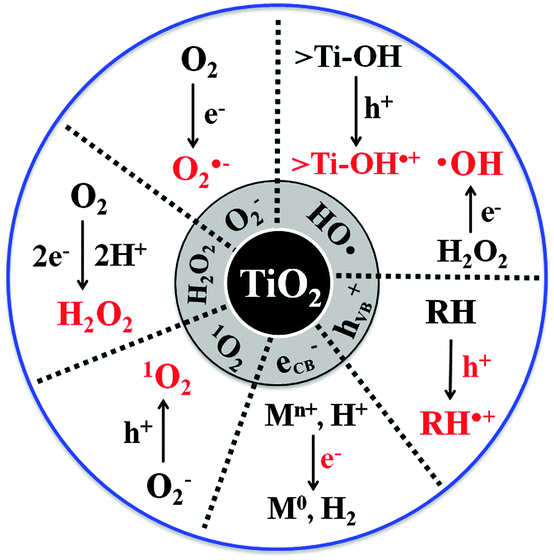 | ||
| Fig. 1 Primary reactive oxygen species (ROS) generated in TiO2 photocatalysis. | ||
Incidentally, considering that the earth crust is mainly composed of metal oxides including potentially photoactive ingredients like iron oxides, it is interesting to note that the lack of significant photoactivity in them under solar irradiation seems to be desirable to make the earth environment habitable for life. The efficient generation of ROS on solar irradiated metal oxides (soils and rocks) would have destroyed organic matters and microorganisms. If water splitting had occurred on sunlit metal oxides, it might have changed the atmospheric composition that would be different from the current one (e.g., elevated H2 concentration in the atmosphere).
2.1. Charge transfers and the accompanying production of reactive species
The oxidation power of photogenerated holes can be modified when impurity dopants (e.g., transition metal ions, N, and C) are introduced into the TiO2 lattice to create extra energy levels within the forbidden bandgap. Owing to the less positive levels of the dopant energy states in comparison to the original VB edge, the oxidizing power of the holes trapped at the dopant sites is less energetic.53,54 This is why the visible light photocatalytic activities of doped TiO2 are often limited compared with those of UV/TiO2.55–58 For example, nitrogen-doped TiO2 failed to catalyze the oxidation of formate (HCOO−) (reaction (1)) under visible irradiation (λ > 400 nm) although it can absorb visible light up to ∼600 nm:55
| HCOO− + h+/˙OH → H+/H2O + CO2˙− | (1) |
The role of OH radicals in PCO processes is widely accepted and the photocatalytic degradation of pollutants on UV-illuminated TiO2 through their action has been demonstrated for a large number of organic compounds. The OH radicals generated on illuminated TiO2 are present mainly in the form of surface bound hydroxyl radicals (˙OHs).4,8 However, it has been demonstrated that some fraction of OH radicals desorb from the surface as unbound radicals (free, ˙OHf) and diffuse into the reaction medium. The previous studies investigated the desorption of ˙OHf at the TiO2/air interface51,65–72 and clearly demonstrated that the OH radicals generated from illuminated TiO2 diffuse through the air to react with a substance that is not in direct contact with the TiO2 surface. The diffusing radicals react with various remote substrates (e.g., carbon soot,51,64,67,73 stearic acid,64 and polymer71) and were demonstrated even to pass through an organic polymer membrane of ∼120 μm thickness.68 The desorption of OH radicals is also allowed at the TiO2/water interface, which was confirmed by a recent study that observed the diffusing ˙OHf from the illuminated TiO2 surface in water through a gap of 7.5 μm using a single molecule detection technique based on total internal reflection fluorescence microscopy (TIRFM).74 In PCO processes, the hole and ˙OHs react mainly with adsorbed substrates and the desorption of intermediates from the surface should inhibit further mineralization. On the other hand, mobile ˙OHf can react with both surface-bound and unbound substrates/intermediates and is a more versatile oxidant. The ˙OHf diffusing from the irradiated anatase TiO2 into the aqueous bulk was observed while that was not observed with rutile as shown in Fig. 2a and b. Therefore, the PCO on rutile is largely limited to the adsorbed substrates, whereas the working range of PCO on anatase is more expanded owing to the presence of mobile ˙OH (Fig. 2c). This mechanism was newly suggested as an explanation for the common observations that anatase has higher activities than rutile for many PCO reactions. Therefore, as for the photocatalytic reductive conversion that does not involve the hydroxyl radical, the intrinsic activities of anatase and rutile are little different.73 However, why anatase allows the desorption of ˙OHf and rutile does not and what properties of the TiO2 surface control the desorption of the active radical at the molecular level are not understood and need to be further explored.
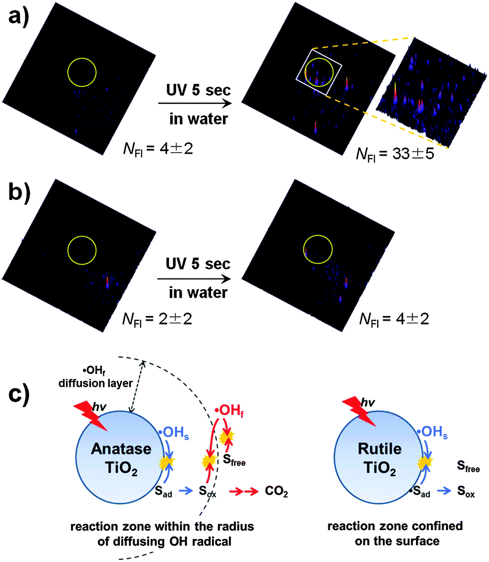 | ||
| Fig. 2 (a and b) Fluorescence images of free hydroxyl radicals (˙OHf) that migrated through a gap from the UV-illuminated TiO2 (a: anatase, b: rutile) to HPF-coated cover glass. The TiO2/water system with silanol-modified HPF (3′-(p-hydroxyphenyl)fluorescein) was compared before (left) and after (right) UV irradiation for 5 s. The diffusion gap is 7.5 μm. The UV irradiation region is inside the yellow circle in the images. NFI indicates the number of fluorescence signals. The size of the image is 50 × 50 μm. (c) Illustration of OH-radical-mediated photocatalysis on anatase and rutile. Reprinted with permission from ref. 74 (Copyright 2014 Wiley-VCH Verlag GmbH & Co. KGaA, Weinheim). | ||
The generation of OH radicals can be changed by modifying the surface of the semiconductor. The surface adsorption of inorganic anions (fluorides, phosphates, and sulfates) may be the simplest method.75,76 The surface fluorination of TiO2, which replaces the surface hydroxyl group with fluoride (reaction (2)),77–82 was suggested to prefer the generation of ˙OHf to ˙OHs because VB holes react mainly with the adsorbed water molecules (not the surface hydroxyl group) under the condition that the surface hydroxyl groups are depleted by the fluoride substitution:83
![[double bond splayed left]](https://www.rsc.org/images/entities/char_e009.gif) Ti–OH + F− → Ti–F + OH− (pKF = 6.2) Ti–OH + F− → Ti–F + OH− (pKF = 6.2) | (2) |
The electron transfer part can also be controlled by modifying the TiO2 surface. Surface platinization is the most commonly employed technique for enhancing the CB electron transfer.108 When Pt is deposited onto TiO2 with creating a Schottky barrier at the interface,109 the Pt phase on TiO2 serves as an electron sink, facilitating the charge separation and retarding charge recombination. The enhanced electron transfer on Pt-deposited TiO2 has been demonstrated in many cases. The electron shuttles (e.g., Fe3+/Fe2+ redox couple) present in the illuminated suspension of semiconductor particles can generate current on a collector electrode and the deposition of Pt on suspended TiO2 particles markedly enhanced the photocurrent (Fig. 3), which demonstrates the role of Pt in facilitating the interfacial electron transfer.37 The accelerated dechlorination of CCl4 in dye-sensitized Pt/TiO2 suspensions is also a good evidence of the role of Pt as an electron transfer mediator:97,98
| CCl4 + ecb− (Pt/TiO2) →˙CCl3 + Cl− | (3) |
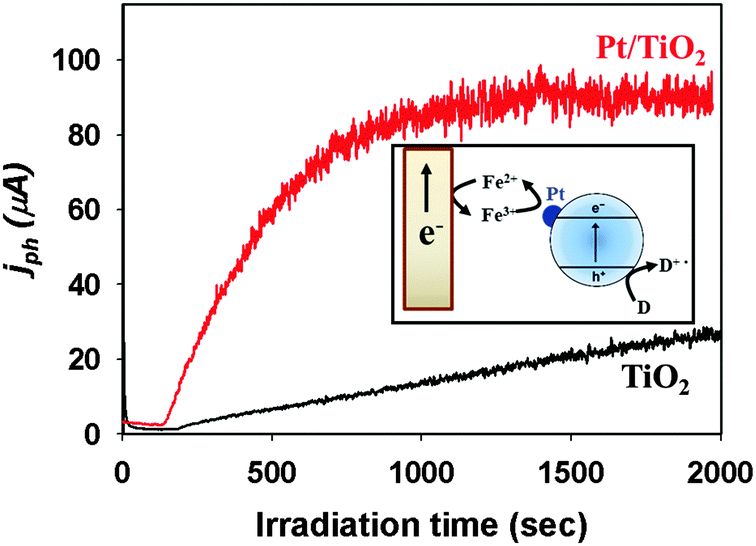 | ||
| Fig. 3 Comparison of Fe3+-mediated photocurrents collected on a Pt electrode for TiO2 and Pt/TiO2. The inset shows the current collection on an inert Pt electrode immersed in an UV-illuminated Pt/TiO2 suspension. Adapted with permission from ref. 150 (Copyright 2014 American Chemical Society). | ||
The scavenging of electrons in Pt subsequently accelerates the hole-mediated oxidation part as demonstrated in numerous cases.8,79,99,110–115 The overall transfer of electrons and holes on semiconductor nanoparticles should be balanced to maintain the charge neutrality. However, the role of Pt is more complex than that of a simple CB electron sink. The presence of Pt not only accelerates the photocatalytic reaction rate but also changes the reaction pathways to generate different products because of the well-known thermal catalytic activity of Pt.99,114,116 In addition, the effects of Pt on the photocatalysis rate are not always positive and negative effects were also reported.99,115 To make the matter more complex, the reported effects of Pt on the photocatalytic degradation of a specific substrate are often contradictory.117–121 In other words, the effects of Pt are highly substrate-specific and depend on the Pt–substrate interaction as well as the intrinsic properties of Pt (size, oxidation state, etc.). For example, the oxidation state of Pt critically influences the initial degradation rate of trichloroethylene (TCE).115 While the photocatalytic activity of Pt0/TiO2 is almost similar to that of bare TiO2, TiO2 loaded with oxidized Pt (Ptox) exhibits negligibly low activity. It was proposed that TCE adsorbed on Ptox chemically mediates the charge recombination through the redox cycle of TCE. The platinization of TiO2 and other semiconductors as a means of enhancing the photocatalytic activity has been very popular, but the overall effects are rather complex and not easy to be generalized. It depends on how the platinized samples are prepared, what are the experimental conditions, and what are the substrates. The effects of the presence of Pt on the semiconductor photocatalytic reactions, though widely practiced and popular, still need to be understood at the molecular level.
The superoxide/hydroperoxyl radical is generally a much weaker oxidant than the VB hole and OH radical, but it can serve as an important oxidant in some cases. An outstanding example is the PCO of arsenite (AsIII) to arsenate (AsV).96,125–129 It has been proposed96,126,127,129,130 and later verified125,128 by time-resolved transient absorption spectroscopy that the arsenite adsorbed on TiO2 serves as an external charge-recombination center, where the reaction of arsenite with holes and OH radicals is immediately followed by a CB electron transfer (Fig. 4). Although the trapped electron transfer to O2 is slow (>20 μs) and the homogeneous bimolecular rate constant between the superoxide and arsenite is as low as 106 M−1 s−1, the presence of the AsIV/AsIII redox couple-mediated null cycle makes the superoxide-mediated oxidation path important in the photocatalytic conversion of AsIII to AsV. The modification of the TiO2 surface may enhance the electron transfer to O2 and inhibits the AsIV/AsIII couple-mediated null cycle with significantly changing the PCO kinetics of arsenite. For example, the loading of co-catalysts such as Pt on TiO2 facilitates the electron transfer to O2 with enhancing the generation of superoxide and accelerating the PCO of arsenite. TiO2 hybridized with reduced graphene oxide (rGO) works similarly as Pt/TiO2 and facilitates the transfer of photo-generated electrons from TiO2 CB to O2, which subsequently hinders the AsIV/AsIII-mediated recombination and enhances the overall arsenic oxidation.
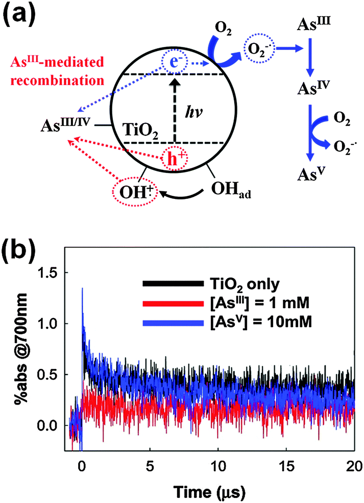 | ||
| Fig. 4 (a) Schematic illustration of As(III) as an external charge recombination center on UV-excited TiO2. (b) Transient absorption time traces (at 700 nm) of TiO2 slurry in the presence of As(III) or As(V). Reprinted with permission from ref. 125 (Copyright 2010 American Chemical Society). | ||
2.2. Multiple charge-transfers
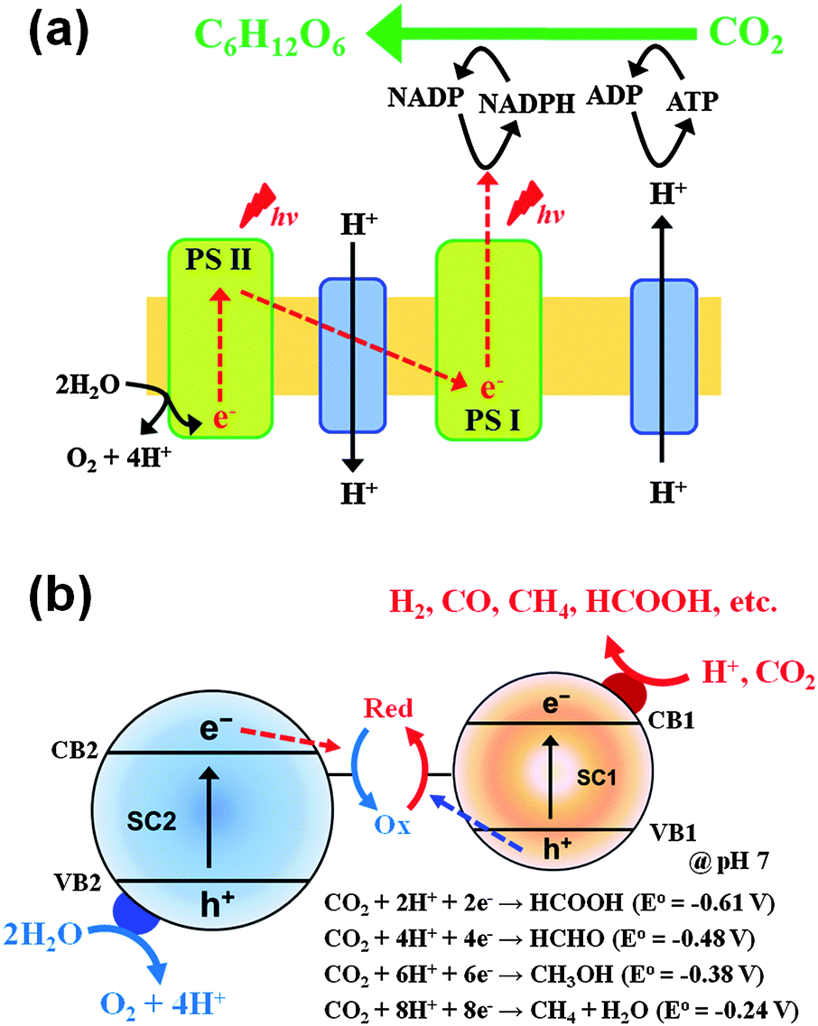 | ||
| Fig. 5 Schematic illustration of the multiple charge transfers occurring in (a) photosynthesis and (b) artificial photosynthesis (Z-scheme). | ||
The presence of Pt is often essential for multi-CTs but its high cost hinders its widespread practical applications. Alternative co-catalytic materials consisting of earth-abundant elements are being actively sought and carbon-based materials including carbon nanotubes,33,35,143,144 graphite,145 and graphene146 have been frequently investigated for this purpose. Such carbon-based materials have unique electronic properties, owing to the conjugated sp2 carbon networks facilitating CT.147 For example, reduced graphene oxide (rGO) was shown to serve as an electron reservoir in TiO2 photocatalysis, retarding the recombination of charge pairs and leading to enhanced photoconversion efficiency (Fig. 6).145,148,149 In a typical preparation of the TiO2/rGO hybrid, TiO2 particles were loaded on the rGO sheet but different geometrical arrangements between rGO and TiO2 particles have a strong influence on the photocatalytic activity.147,150,151 The hybridization of nanometer-sized GOs and TiO2 nanoparticles induces a self-assembled core/shell structure which highly enhances the interfacial contact between them in comparison with the particles-on-a-sheet geometry. GO in direct contact with TiO2 can be photocatalytically reduced, which leads to the formation of TiO2/rGO core/shell (Fig. 6a). This composite clearly differentiates itself from the conventional TiO2/rGO composite that is based on the larger μm-sized rGO sheet (particles-on-a-sheet: TiO2/rGO sheets). The photocatalytic activities of the core/shell are significantly higher than those of bare TiO2 for hydrogen production (Fig. 6b). In another geometry, TiO2 nanofibers (NFs) in which GO sheets were incorporated within the NF matrix (GO–TiO2 NFs) were also prepared and tested for their photocatalytic and PEC activities (Fig. 6a). The GO sheets embedded in TiO2 NFs improve the interparticle connection and facilitate the charge pair separation by serving as an in-built electron conduit with enhancing the photoactivity (Fig. 6c).152 Even though the photocatalytic activities of TiO2 hybridized with various forms of carbon nanomaterials are higher than those of bare TiO2 in many reported cases including the above examples, they are usually lower than those of Pt/TiO2. However, the co-presence of carbon nanomaterials along with Pt further enhances the photocatalytic activities of Pt/TiO2. The simultaneous loading of Pt and rGO on TiO2 (ternary hybrid) markedly enhanced the photocatalytic production of H2, as compared to the binary hybrids (Pt/TiO2 and TiO2/rGO) (Fig. 6b). This indicates that rGO can act as an auxiliary co-catalyst, thereby reducing the amount of expensive Pt required for H2 production.
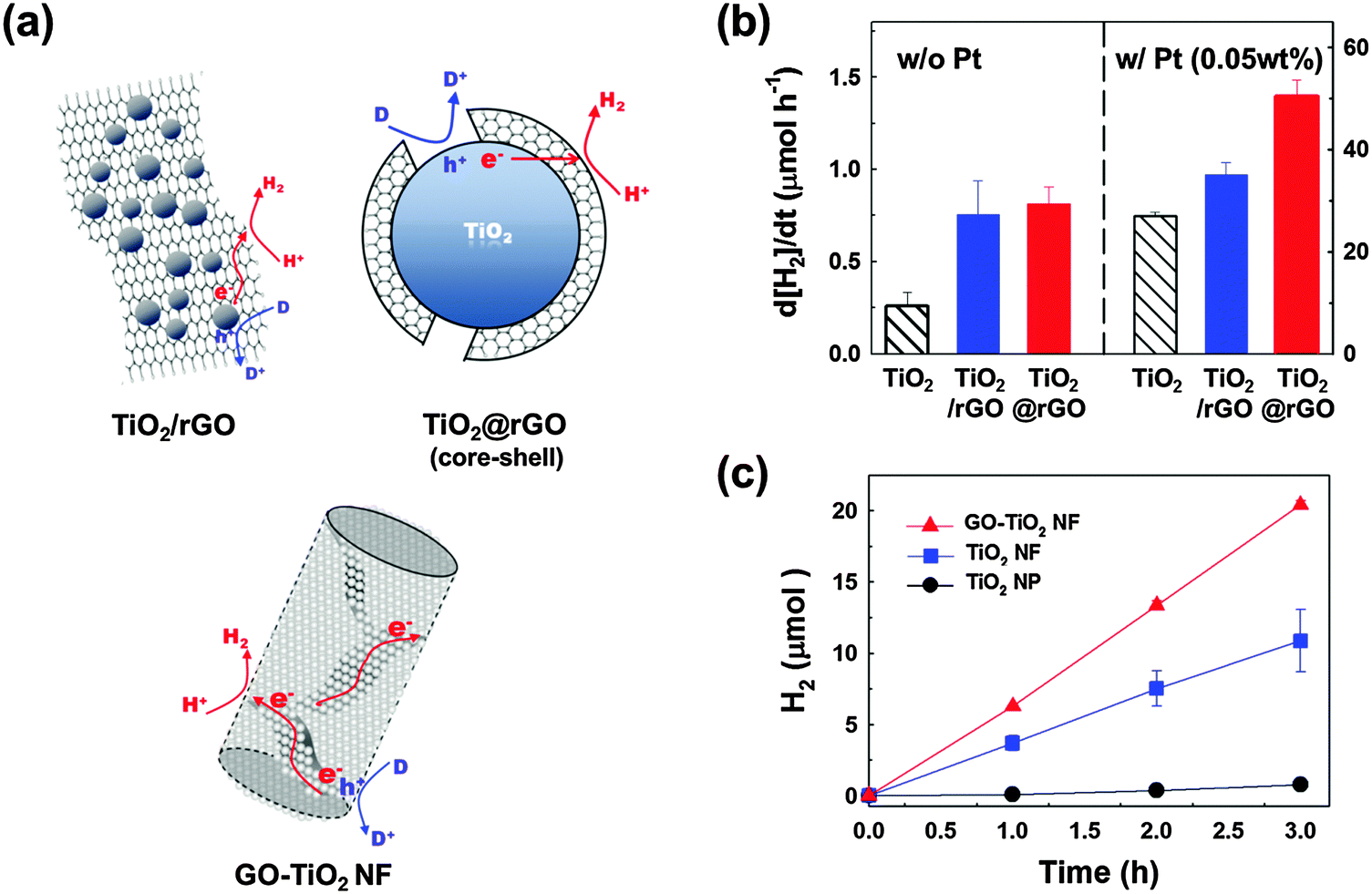 | ||
| Fig. 6 (a) Illustration of the various composite structures of TiO2 and (r)GO sheets and the associated charge transfers for hydrogen production. (b) Photocatalytic H2 production rates in the aqueous suspensions of TiO2, TiO2 dispersed on a 2D rGO sheet, and the TiO2/rGO core/shell structure before (left panel) and after Pt loading (right panel). (c) Time profiles of H2 production in the aqueous suspensions of TiO2 nanoparticles (NPs), TiO2 nanofibers (NFs), and GO embedded in TiO2 NFs (GO–TiO2 NF). (a and b) Adapted with permission from ref. 149 (Copyright 2012 American Chemical Society). (a and c) Reprinted from ref. 152 with permission by Elsevier. | ||
In addition, rGO was found to be an excellent catalyst to drive the photocatalytic production of H2O2 in aqueous TiO2 suspension.151 rGO/TiO2 displayed the highest photocatalytic activity in producing H2O2 (via PCETs to molecular oxygen) in aqueous 2-propanol solution compared with noble metal-loaded TiO2 (Fig. 7a). The leveling-off of H2O2 production is attributed to the in situ decomposition of produced H2O2 and the relevant kinetics can be expressed with [H2O2] = (kf/kd)[1 − exp(−kd·t)] (kf and kd refer to the formation and decomposition rate constants, respectively).131,153 According to the kinetic analysis, kf with rGO/TiO2 was not the largest, whereas kd with rGO/TiO2 was the smallest, leading to the highest net yield of H2O2 production. The photocatalytic decomposition of H2O2 can be further retarded by adsorbing phosphate on rGO/TiO2 because the adsorbed phosphate inhibits the adsorption of H2O2 (Fig. 7b). When Co2+ was present together with phosphate, cobalt-phosphate complexes (CoPi) were in situ formed on rGO/TiO2 (Fig. 7c). The ternary rGO/TiO2/CoPi produced H2O2 at ∼80 μM in the absence of any sacrificial hole scavenger, which was far more efficient than rGO/TiO2 (Fig. 7b).
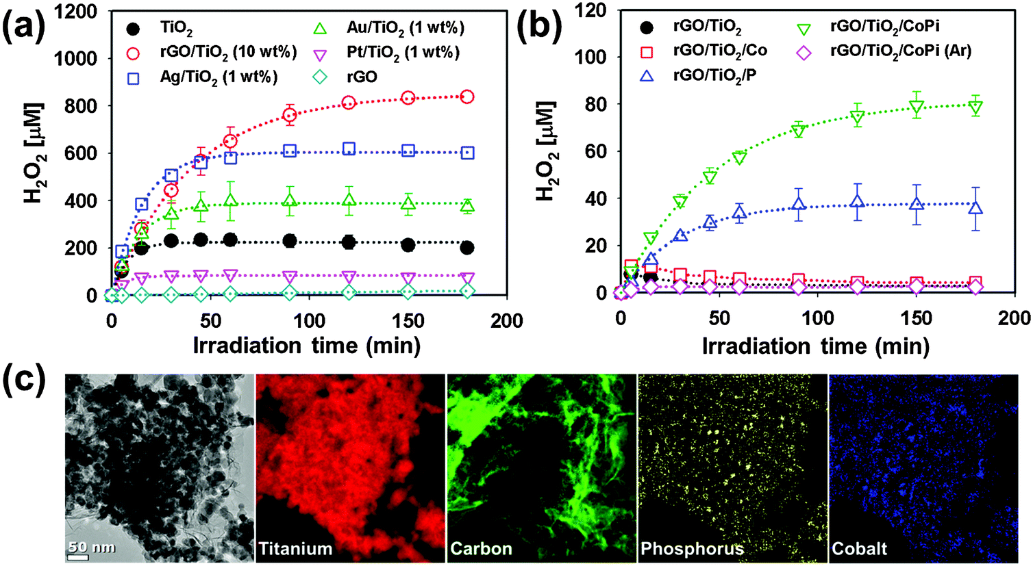 | ||
| Fig. 7 Photocatalytic production of H2O2 (a) in the presence of 2-propanol and (b) in the absence of 2-propanol as a result of water oxidation. (c) TEM image and EELS mapping of rGO/TiO2/CoPi. Reproduced from ref. 151 with permission from The Royal Society of Chemistry. | ||
Other materials can be employed as a modifier of TiO2 for enhancing the multiple CTs. For the conversion of CO2 to hydrocarbons, for example, a thin Nafion layer can be coated on the Pd/TiO2 nanoparticles to facilitate PCETs as well as to inhibit the re-oxidation of the intermediates and products.154 It was found that the introduction of the Nafion layer enhanced the production of methane, ethane, and propane in UV-irradiated Pd/TiO2 suspensions. The effect of the Nafion overlayer on TiO2 seems to be related to its roles to maintain the local proton activity within the layer to facilitate PCET reactions (as a proton conductor) and to inhibit the photooxidation of the intermediate products of CO2 reduction (as a barrier layer for the oxidation of reaction intermediates). The Nafion layer may stabilize the intermediates, inhibit the re-oxidation of the CO2 reduction products, and subsequently may assist in the serial electron transfers to produce the final products. The perfluorinated backbone of Nafion itself resists the photooxidation, and therefore, the photoactivity of the Nafion/Pd/TiO2 composite can be sustained under UV irradiation. Incidentally, owing to the cation exchange property of Nafion, the Nafion-coated TiO2 has also been employed as a photocatalyst that selectively adsorbs cationic substrates or cationic sensitizers.94,95
To achieve the overall photoconversion, the PCET half reactions should be coupled with the oxidation half reactions which supply the protons and electrons. The most ideal counterpart should be the oxidation of water, which also involves the multi-electron transfers (requiring four proton/electron couples) and should also be limited by the photon flux. The photooxidation of water is an important building block in photosynthesis because it is the only reaction that can supply the electrons and protons for a global-scale production of solar fuels.17,155–157 Although the VB holes in most oxide semiconductors have the oxidation potential high enough to drive water oxidation, the water oxidation part always kinetically limits the overall photoconversion. In most photocatalytic oxidation processes occurring on bare metal oxide semiconductors, the oxidation of water preferentially generates the transient hydroxyl radical species which has little chance to be further oxidized to O2via multiple hole transfers. To overcome this problem, water oxidation catalysts such as cobalt phosphate (CoPi) and nickel borate (NiBi) complexes can be deposited on the semiconductor electrode (mostly non-TiO2 electrodes such as BiVO4).29,30,158 The application of anodic biases to the semiconductor electrode oxidizes the deposited cobalt(II) and nickel(II) species (e.g., Co2+ + 2h+ → Co4+), which form complexes with phosphate and borate under illumination. The oxidized species then return to their original oxidation state through oxidizing water (e.g., Co4+ + H2O → Co2+ + 1/2O2 + 2H+). Although this catalytic material is composed of earth-abundant elements and easy to be prepared, it can serve as a charge recombination center because of the sluggish interfacial hole transfer under certain conditions (e.g., large anodic bias, thick coat, etc.).29,41 Incidentally, the water photooxidation on semiconductor electrodes can also be enhanced by passivation of the semiconductor surface by a thin insulating overlayer, which reduces the number of electron trapping sites on the semiconductor surface, thereby facilitating water photooxidation despite the insulating nature of the overlayer (e.g., a thin Al2O3 overlayer on the WO3 photoanode surface).159
3. Interparticle charge transfers
Efficient charge separation can be achieved by interparticle CTs through particle-to-particle junctions. The interparticle CT reduces the chance of charge recombination and eventually increases the overall photocatalytic activities. It occurs both in single semiconductor systems (e.g., agglomerates of colloidal nanoparticles160,161 and compactly packed nanoparticles162,163) and in hybrid semiconductor-composite systems (binary26,32,164,165 and ternary hybrids25). Colloidal or suspended semiconductor particles exist almost always as agglomerates in aqueous solution. Hence, the effects of the agglomerate state on the charge separation and transfer need to be carefully considered. The agglomeration of semiconductor particles is usually thought to have a negative effect on the photocatalytic activity because of the reduced surface area and the enhanced light scattering loss. However, the overall effect of agglomeration seems to be more complex than thought.3.1. Homojunction semiconductor systems
A recent study reported that the photocatalytic H2 production in TiO2 suspension containing nitric acid is greatly accelerated after some induction period (Fig. 8a).160 This unique phenomenon was attributed to the pH increase resulting from the in situ photocatalytic reduction of nitrate to ammonia. As the solution pH approaches the zero point charge of TiO2 (pHzpc ∼ 6.9), a rapid agglomeration of the TiO2 colloid is induced, which initiates the production of H2. The colloid agglomeration and the appearance of H2 production are coincident. A similar behavior was observed in the case of photocurrent generation (mediated by the MV2+/MV+ redox couple; E° = −0.445 V) in TiO2 colloids: a rapid increase in the photocurrent was observed after the agglomeration of TiO2 nanoparticles. A plausible explanation is that the charge separation is facilitated by electron hopping from particle to particle when TiO2 nanoparticles are connected with each other within the agglomerates. Hence, the agglomeration-induced acceleration of H2 and photocurrent generation are ascribed to the facilitated charge separation by interparticle CT within the agglomerates.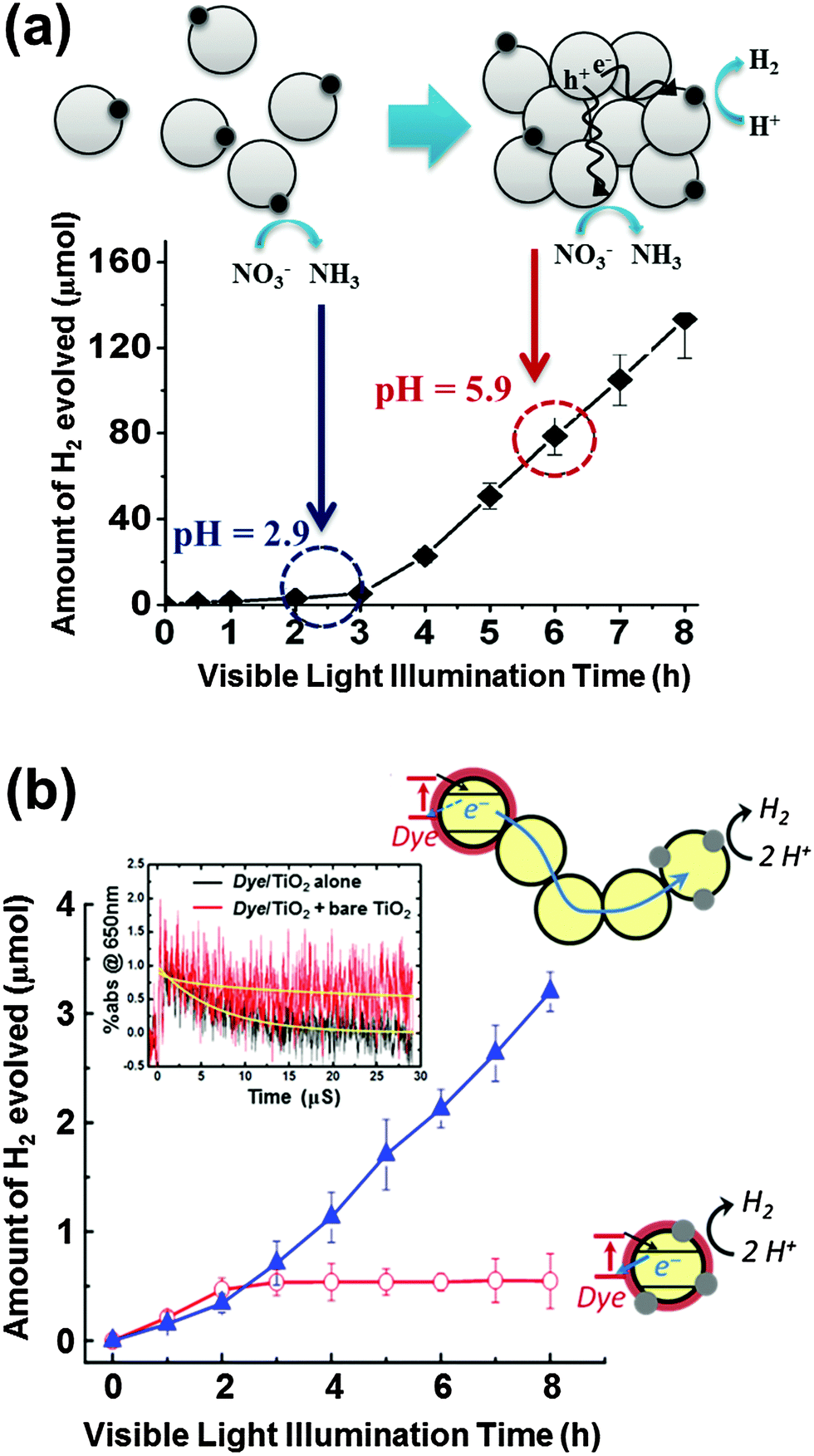 | ||
| Fig. 8 (a) Time trend of H2 evolution in colloidal TiO2 synthesized using HNO3 and schematic illustration showing well-dispersed colloidal TiO2 nanoparticles at pH 2.9 and agglomerated TiO2 nanoparticles (pH 5.9). Adapted with permission from ref. 160 (Copyright 2008 American Chemical Society). (b) Schematic illustration and visible light induced production of H2 in the aqueous suspension of dye/TiO2/Pt and [dye/TiO2 + TiO2 + TiO2/Pt]. The inset shows the normalized time traces of absorption at 650 nm (dye˙+) during the 532 nm laser photolysis of dye/TiO2 without bare TiO2 and [dye/TiO2 + bare TiO2]. Adapted with permission from ref. 161 (Copyright 2013 American Chemical Society). | ||
The effect of interparticle CTs in the agglomerates of dye-sensitized TiO2 nanoparticles was also systematically studied by using both static photocatalysis and transient laser spectroscopy.161 A typical dye-sensitized system for H2 production includes dye-sensitized TiO2 nanoparticles (dye/TiO2) as a light absorber and platinized TiO2 (Pt/TiO2) as an active catalytic center. Fig. 8b compares two experimental cases of dye sensitization: a common case where the light absorbing dye and the Pt catalyst are on the same nanoparticle (dye/TiO2/Pt) and the other case where each part is separated in different nanoparticles and bare TiO2 nanoparticles are added to mediate between two active parts (dye/TiO2 + TiO2 + Pt/TiO2). When the light absorbing part of dye/TiO2 is separated from the active catalytic center of Pt/TiO2, the role of bare TiO2 nanoparticles working as a mediator that connects the above two parts in the agglomerates should be essential. The presence of mediator in the agglomerate indeed facilitated the charge separation (i.e., retarding charge recombination between the oxidized dye and the injected electrons) and the electron transfer from dye/TiO2 to Pt/TiO2 through multiple grain boundaries subsequently produced more H2 (Fig. 8b). A similar phenomenon was also observed in the case of dye-sensitized reduction of Cr(VI) to Cr(III):161 a notable enhancement of Cr(VI) reduction was observed when bare TiO2 nanoparticles were incorporated as a mediator in the dye-sensitized TiO2 system. The transient absorption spectroscopic measurements revealed the role of the mediator TiO2 nanoparticles by monitoring the transient absorption decay of the photogenerated dye cation (dye˙+). An increase in the bare TiO2 amount (as a mediator in the dye-sensitized TiO2 system) enhanced the average lifetimes (τ) of the dye cation by ∼18 times (from 6.7 μs to 120 μs) in the aggregated state (Fig. 8b inset).
To utilize the interparticle CT phenomenon in practical applications, particulate mesoporous TiO2 (meso-TiO2) with well-ordered pore structures and unique morphologies was developed without the use of templates via the hydrothermal method (Fig. 9a).162 The formation of meso-TiO2 is governed by the electrostatic potential, which can be controlled by the ionic strength of the solution. By changing the solution ionic strength (e.g., by adding KCl), which controls the hydrolysis of the titanium alkoxide precursor, a mesoporous structure consisting of densely packed nanoparticles was synthesized. The as-synthesized meso-TiO2 microspheres (0.5–1 μm) consisting of small primary nanoparticles (10–15 nm) exhibit markedly enhanced photo(electro)chemical activities for both H2 production and photocurrent generation (through the methyl viologen redox couple in the suspension), compared to colloidal TiO2 and commercial TiO2 nanoparticles (P25 and Hombikat UV-100). The higher photocatalytic activity of meso-TiO2 is attributed to the compact packing of TiO2 nanoparticles forming uniform agglomerates, which enable the efficient charge separation through the interparticle CT.
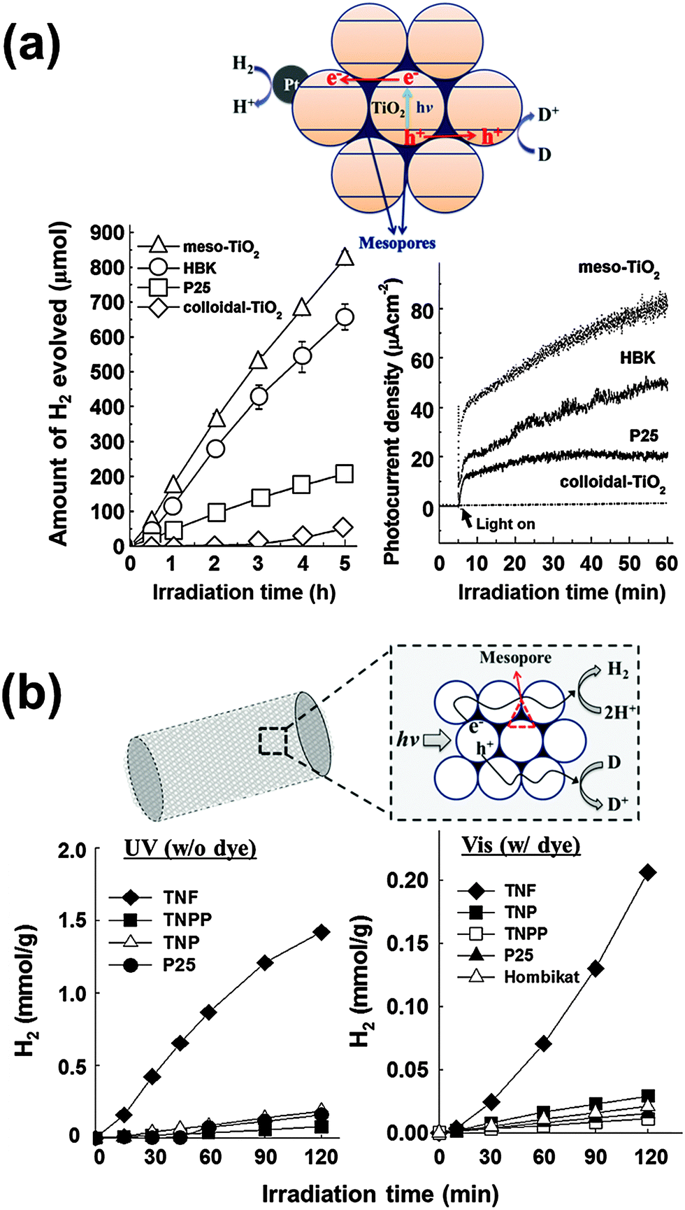 | ||
| Fig. 9 (a) Time courses of H2 evolution and photocurrent generations by different TiO2 photocatalysts and schematic illustration of mesoporous TiO2 microspheres. Adapted with permission from ref. 162 (Copyright 2007 American Chemical Society). (b) Time courses of H2 evolution in aqueous suspensions of TiO2 nanofibers (λ > 320 nm) and dye-sensitized TiO2 nanofibers (λ > 420 nm) with schematic illustration of mesoporous TiO2 nanofibers. Reproduced from ref. 166 with permission from The Royal Society of Chemistry. | ||
TiO2 fibers consisting of nanoparticles represent another good example of effective interparticle CT. It is well known that electrospinning of pre-crystallized TiO2 nanoparticles creates well-ordered and aligned high surface area mesoporous TiO2 nanofibers that are ∼500 nm in diameter and a few micrometers in length (Fig. 9b).163 The photocatalytic activity comparison between the titania nanofibers (TNF) and the nanoparticles (TNP) indicated that the former had 3 times higher activities in photocurrent generation and 7 times higher in H2 production. The photocatalytic superiority of TNF is attributed to the effects of mesoporosity and nanoparticle alignment, which help efficient charge separation through interparticle CT along the nanofiber framework. The TNF also exhibited 7 times and >140 times higher dye-sensitized H2 production, compared to the TNP and commercial TiO2 samples, respectively.166 These studies, therefore, provide strong evidence that the charge separation efficiency could be markedly enhanced through interparticle CTs when the individual nanoparticles are directionally arranged with close contacts among them.
3.2. Multi-hybrid semiconductor systems with heterojunctions
Combining two different types of semiconductor particles with heterojunctions has been frequently employed as a means of enhancing charge pair separation and thereby enhancing the overall photocatalytic activity.25,167 A proper selection of semiconductors based on their CB and VB positions leads to the cascaded transfer of photogenerated charge carriers from one semiconductor to another. A variety of binary composites consisting of TiO2 and other semiconductors (e.g., WO3,26,84,168–170 SnO2,171–173 ZrO2,173 CdSe,174,175 and CdS25,32,176,177) have been prepared and tested for their photocatalytic activities.Among the binary TiO2 composites with heterojunctions, WO3/TiO2 composite photocatalysts have been most frequently studied for environmental remediation and solar energy storage.26,168–170,178–181 The primary role of WO3 is to accept TiO2 CB electron. Since WO3 has a lower (more positive) CB potential than that of the TiO2 CB, the TiO2 CB electrons are transferred to the WO3 CB with reducing W(VI) to W(V). The reduced state of WO3 (e.g., as a form of HxWO3) is maintained for a period of time and the stored electrons are slowly released to the surrounding electron acceptors (e.g., O2) (Fig. 10a).26,182,183 This photocharge–discharge mechanism has been applied to the corrosion prevention of metals by coating the metal surface with the composite semiconductors. This mechanism was also successfully applied to the conversion of water pollutants (phenol, Cr(VI), etc.).26,168 The coupling of TiO2 with WO3 decreased the photocatalytic activities in some cases (e.g., for the gas-phase oxidation of acetaldehyde and the liquid-phase oxidation of 2-naphthol),178 In addition, the PCO activity of WO3/TiO2 for 1,4-dichlrobenzene was shown to be highest only at a certain ratio of WO3 to TiO2, and higher loadings of WO3 above this fraction decreased the activity significantly.181 The reduced activity is ascribed to a retarded rate of electron transfer from the WO3 CB (0.3–0.5 VNHE) to O2, since its potential is more positive than the O2 reduction potential (E°(O2/O2−˙) = −0.33 VNHE). This problem can be overcome by loading Pt nanoparticles on WO3, which enables the multi-electron reduction of O2, which has a more positive potential (e.g., E°(O2/H2O2) = +0.695 VNHE for two-electron reduction) than the one-electron reduction.184 Consequently, the PCO reactions occurring on Pt/WO3 were markedly enhanced because the reductive decomposition of H2O2 (in situ generated from the reduction of O2) produced OH radicals under visible light.23
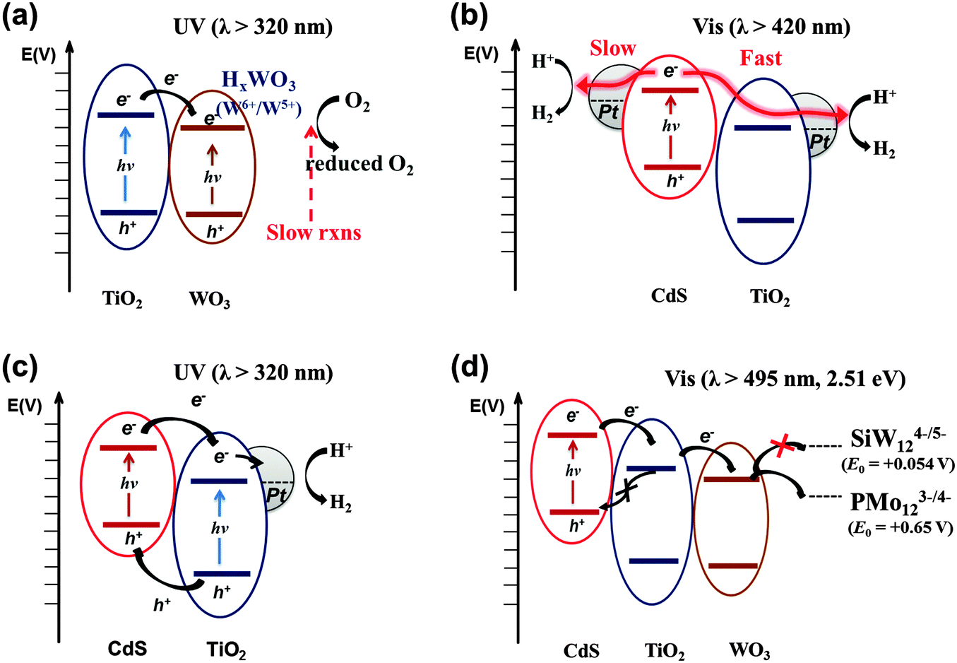 | ||
| Fig. 10 Schematic illustration of the electron-transfer processes in multi-junction systems under UV and visible light. (a) TiO2/WO3, (b and c) CdS/TiO2/Pt, and (d) CdS/TiO2/WO3. | ||
On the other hand, the mismatch of the CB and VB levels in coupling semiconductor systems may reduce their photocatalytic and PEC activities on the contrary. The hybridization of hematite (α-Fe2O3) on TiO2 nanotube arrays unexpectedly decreased PEC and photocatalytic activity (for phenol degradation), primarily due to the low conductivity of hematite and the band position mismatch between TiO2 and hematite (the CB and VB of hematite being more positive and negative, respectively, with respect to those of TiO2).164 Such mismatch results in enhanced charge recombination.
As for the TiO2 hybrid with non-oxide semiconductors, CdS/TiO2 is the most representative example and has been widely applied to the photocatalytic conversion of various substrates such as methane,185 methyl orange,186 indole,187 acid orange II,188 1,2,3,4-tetrachlorobenzene,189 and methylene blue and eosin.190 The VB and CB of CdS are ideally placed in comparison to those of TiO2 for efficient charge pair separation and the bandgap of CdS is narrow (∼2.5 eV) enough to absorb a substantial portion of solar visible light (λ ≤ 500 nm). Upon excitation by visible light, the CdS CB electrons are transferred to the TiO2 CB, while the holes remain in the CdS VB (Fig. 10b). Under optimal conditions, the semiconductor coupling reduces the average emission lifetime of CdS by a factor of four (24.6 to 6.8 ns), owing to the scavenging of the CB electrons by TiO2.191 The electron transfer from CdS to TiO2 is sensitively influenced by the CB edge potential difference. As the CdS particle size decreases to the quantum confinement domain, the bandgap of CdS is widened. As a result, the CB edge of CdS rises with respect to that of TiO2, which increases the driving force of CB electron transfer from CdS to TiO2.192,193
The CdS/TiO2 composite can be further modified by noble metal (Pt) nanoparticles. In this ternary configuration (i.e., CdS, TiO2, and noble metal), both semiconductors can be simultaneously excited at different wavelength regions (λTiO2 < 400 nm; λCdS > 400 nm) due to their different bandgaps. Upon excitation of both CdS and TiO2, CB electrons and VB holes are separated to TiO2 and CdS, respectively, while electrons are effectively collected at metal nanoparticles (Pt) deposited on TiO2 (Fig. 10c). This CT process mimics that of natural photosynthesis194 in terms of two-photon excitation (PS-II and PS-I in Z-scheme: see Fig. 5a). It is important that Pt is loaded selectively on the TiO2 surface only among the CdS/TiO2 composites since the electrons are transferred to the TiO2 side. For example, the photoplatinized hybrid of CdS/TiO2 [resulting in Pt–(CdS/TiO2) where Pt is loaded on both CdS and TiO2] is much less efficient than the hybrid of CdS/(Pt–TiO2) [Pt is photodeposited on TiO2 first followed by the deposition of CdS]. The CdS/(Pt–TiO2) exhibits 3–30 fold higher H2 production compared to Pt–(CdS/TiO2).32
Another ideal candidate for a non-oxide semiconductor coupled with TiO2 is TaON. The narrow bandgap of TaON (∼2.4 eV),195 along with the negatively shifted CB and VB edges compared to those of TiO2, induces efficient charge separation at the TiO2/TaON interface. Nevertheless, there have not been many studies on the coupling of TaON and TiO2, owing to the harsh synthesis conditions of TaON. The synthesis of TaON generally requires high temperature nitridation (at over 850 °C),196 which induces particle coarsening and phase transformation of the counter semiconductor (e.g., the transformation of TiO2 to TiN).21,197,198 Recently, a TaOxNy thin layer coupled with TiO2 nanotubes (TNTs) was prepared by a low temperature nitridation process (500 °C) and the TNT composite exhibited much improved PEC water-splitting efficiencies under both visible (3.6 times) and UV (1.8 times) illumination compared to bare TNTs because of the efficient charge pair separation at the heterojunction interface of TaOxNy/TNTs (Fig. 11).199 In addition, the thin TaOxNy layer on TNTs serves as a passivation layer that reduces the surface trap sites and enhances the visible light absorption range.
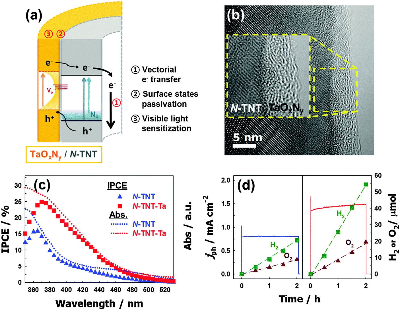 | ||
| Fig. 11 (a) Schematic illustration of charge transfers in an N-TNT–Ta hybrid. (b) Energy-filtered TEM (EF-TEM) image of an N-TNT–Ta hybrid. (c) IPCE spectra of N-TNT (triangle) and N-TNT–Ta (square) as a function of the incident light wavelength. Dotted lines represent the absorption spectra. (d) Photocurrent transients and the concurrent generation of H2 and O2 with N-TNT (left panel) and N-TNT–Ta (right panel) electrodes polarized at +0.9 V vs. Ag/AgCl under UV illumination (λ > 320 nm). Reproduced from ref. 199 with permission from The Royal Society of Chemistry. | ||
Ternary hybrid systems have received less attention because of the complexity while the binary systems have been extensively studied. To evaluate the effects of the ternary systems, a systematic study was conducted with CdS/TiO2/WO3 hybrids, which have cascadal positioning of the CB edges (see Fig. 10d). In this study, only CdS was selectively excited under the irradiation of λ > 495 nm (equivalent to 2.51 eV), in order to focus on the cascaded electron transfer starting from CdS in the ternary hybrid. The photocatalytic reduction of polyoxometalate (POM) (E°(PMo12O403−/4−) = +0.65 VNHE) and PEC tests indicated that the CdS/TiO2/WO3 ternary hybrid has much higher activities compared to bare CdS and binary hybrids (CdS/TiO2 or CdS/WO3) because of the cascadal electron transfer through two sequential heterojunctions (CdS → TiO2 → WO3). Unlike the binary system where the separated charge pairs may recombine directly at the heterojunction, the two sequential heterojunctions along the potential gradient reduce the chance of direct recombination of charge carriers because the electron can be further transferred to the third compartment. The presence of TiO2 in between CdS and WO3 provides an energy barrier for the back electron transfer (Fig. 10d). However, the cascadal electron transfer from CdS to TiO2 to WO3 reduces the reduction potential of CB electrons progressively, which limits the range of reductive conversions that can be driven by the ternary hybrid photocatalytic system. For example, when tungstosilicate (SiW12O404−), which has a more negative one-electron reduction potential (E° = +0.054 VNHE) compared to the WO3 CB, was used as an alternative POM, the efficiency of the photocatalytic reduction was markedly diminished. The cost of enhancing the charge separation efficiency in the hybrid structure is to make the electrons less energetic.
4. Visible light-induced charge transfers
Visible light sensitization of wide bandgap semiconductors like TiO2 has been intensively investigated as one of the most important research topics in photocatalysis. Unlike the heterojunction semiconductors and impurity-doped semiconductors which are modified primarily by inorganic components, the visible light sensitization of semiconductors can also be achieved by coupling with organic substances. There are two main methods for achieving visible light-induced CT: dye-sensitization166,200,201 and ligand-to-metal charge transfer (LMCT).202–2114.1. Dye sensitization
Dye-sensitization of semiconductor photocatalysts is conceptually similar to the operation mechanism of dye-sensitized solar cells.15,212 In principle, the dye molecules located at the TiO2/solution interface are photoexcited and subsequently inject electrons into the TiO2 CB (Fig. 12a). These electrons are subsequently transferred to electron acceptors to induce various redox reactions at the semiconductor interface. For effective electron injection from the excited dye to TiO2, it is necessary to firmly anchor the dye molecules onto the TiO2 surface. In aqueous environments, the adsorption of dyes usually proceeds via electrostatic interaction with the amphoteric TiO2 surface (Ti–OH2+ ↔ Ti–OH ↔ Ti–O−),4,8 the surface charge of which depends on the solution pH. For example, the most commonly used ruthenium bipyridyl complexes (Ru-bpy) with carboxylate anchoring groups are readily anchored to the TiO2 surface in the acidic pH region,97,98,213–215 because the point of zero charge of TiO2 is at around pHzpc ∼ 6 (Fig. 12b).4,8,75 At pH < 6, the surface of TiO2 is positively charged and attracts the carboxylate anion anchoring groups and the dye anchoring is efficiently achieved. The sensitization of anchored dyes can successfully induce H2 evolution201,214,215 and the conversion of water pollutants (e.g., dechlorination of CCl4 and reduction of Cr6+) under visible light.97,200,201 However, at pH > 6 where the TiO2 surface is negatively charged, the anionic dyes are electrostatically repelled and the sensitization efficiency decreases.200,201,213,214 Organic dyes with carboxylate groups also show similar behaviors.200,201 To widen the working pH range, the carboxylate anchoring group can be replaced with a phosphonate group.213,216 TiO2 sensitized with Ru-bpy containing phosphonate groups shows activity for H2 evolution even at alkaline pH (∼9). The number of anchoring groups (carboxylates vs. phosphonates) also significantly influences the photoefficiency and stability of dye-sensitized TiO2 systems.213,216 Irrespective of the kind and number of anchoring groups, the pre-adsorption of dyes on TiO2 is usually required for the initiation of the sensitization.
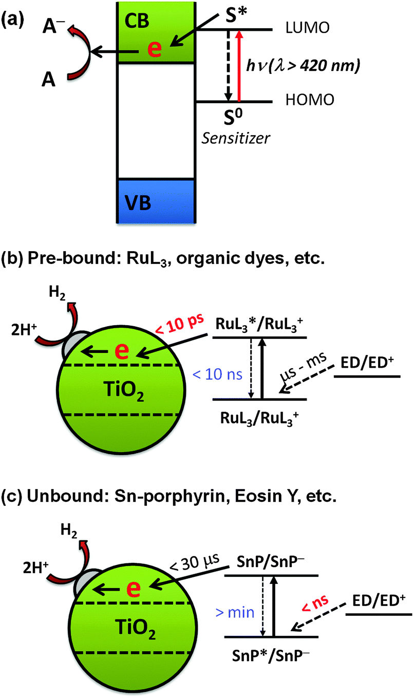 | ||
| Fig. 12 Schematic illustration of (a) the dye-sensitization mechanism, (b) sensitization by pre-bound dyes, and (c) sensitization by unbound dyes. Reproduced from ref. 217 with permission from The Royal Society of Chemistry. | ||
Interestingly, some studies have shown that the presence of pre-adsorbed dye is not always necessary for dye sensitization in aqueous environments. One example is the tin(IV)-porphyrin (SnP)-sensitized TiO2 system (Fig. 12c).217 SnP has a strong oxidative power due to the high charge on Sn(IV)218,219 and hence the excited SnP shows a high photoactivity for the oxidation of aqueous organic compounds. Although the adsorption of SnP on TiO2 is negligible in the pH range of 3–11, a significant amount of H2 was produced in the SnP/TiO2 system (turnover number of 410 and quantum efficiency of ∼35% at an irradiation wavelength of 550 nm).217 Laser flash photolysis showed that the free excited SnP is first reduced by an electron donor (e.g., EDTA) owing to its strong oxidation power in the nanosecond time scale. The high charge on Sn(IV) makes the SnP ring highly electrophilic, favoring the formation of the SnP π-radical anion (SnP˙−). The lifetime of the π-radical anion is long enough (in the order of microseconds) to survive during the slow diffusion from the solution bulk to the TiO2 surface. As a result, the adsorption of SnP on TiO2 is not a required condition for H2 production. This is in contrast with the case of the Ru-bpy/TiO2 system, where the electron transfer from the electron donor to Ru-bpy is 6–9 orders of magnitude slower than the electron injection from the excited Ru-bpy to TiO2.
4.2. Ligand-to-metal charge transfer (LMCT) sensitization
An alternative modification method for visible light activation of TiO2 is to form CT complexes between TiO2 and the surface adsorbate (ligand), neither of which absorbs visible light.210,220,221 This CT-complex-mediated visible light sensitization operates by a mechanism that is different from the aforementioned dye sensitization. In the CT-sensitization, the electron is photoexcited directly from the ground state (HOMO level) of the adsorbate (ligand) (without involving the excited state of the adsorbate) to the semiconductor CB with mainly metal orbital characters (so named as ligand-to-metal charge transfer, LMCT) (Fig. 13a), whereas the dye sensitization is mediated through the excited dye state. Many examples of CT-complex formation on the TiO2 surface have been reported. The TiO2–catechol complex is a classical example of CT-complexation. A theoretical calculation study provided evidence that the visible light absorption is caused by the LMCT and the excited state of catechol is not significantly involved in the photoinjection process.208 8-Hydroxyorthoquinoline and 1,1-binaphthalene-2,2-diol also form complexes with the TiO2 surface, absorbing visible light and exhibiting some activity for H2 production under visible light.202,203 Many organic compounds with phenolic or carboxylic groups (e.g., chlorophenol205 and calixarene206) are able to make LMCT-complexes with the TiO2 surface for visible light absorption. Upon coupling with TiO2, the relatively electron-rich compounds with linker groups (e.g., enediol, carboxylate, nitrile, and alcohol) exhibit a LMCT band in the visible region, whereas the less electron-rich compounds (e.g., thiocyanate) display the band in the UV region.209 The HOMO level of the adsorbate is also very important in determining the active light absorption range of the LMCT system. If there is strong coupling between the molecular orbital (HOMO) of the adsorbate and the energy band of the semiconductor, a new absorption band could appear that is absent in either the adsorbate or the semiconductor alone. Incidentally, the fact that pure TiO2 sometimes exhibits visible light activity for the degradation of organic substrates that do not absorb visible light at all can be ascribed to the LMCT mechanism. For example, phenol and 4-CP can be successfully degraded with the production of chloride ions or/and CO2 in the visible light illuminated (λ > 420 nm) aqueous suspension of pure TiO2 although neither TiO2 nor phenolic compounds absorb visible light.205 This is because the phenolic compound adsorbed on TiO2 (though very weakly) can inject an electron to the TiO2 CB through LMCT with oxidizing itself.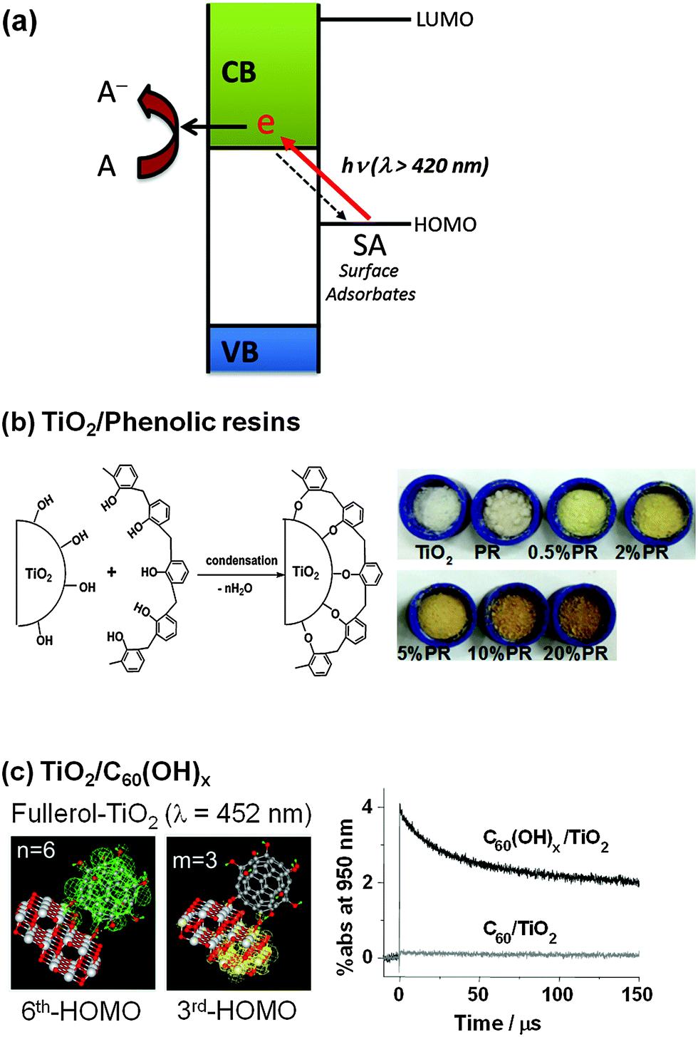 | ||
| Fig. 13 Schematic illustration of (a) the ligand-to-metal charge transfer (LMCT) mechanism, (b) LMCT by phenolic resins, and (c) LMCT with the adsorbates of C60(OH)x. (b) Reproduced from ref. 211 with permission from The Royal Society of Chemistry. (c) Reprinted with permission from ref. 207 (Copyright 2009 Wiley-VCH Verlag GmbH & Co. KGaA, Weinheim). | ||
LMCT sensitization with relatively cheap and commonly used compounds is also noteworthy. For example, ethylenediaminetetraacetate (EDTA) and formate that are widely utilized as electron donors in photochemical conversion systems can induce the LMCT-sensitization by forming surface complexes. The complexation of EDTA (or formate) on TiO2 induces visible light absorption up to ∼550 nm and exhibits a significant visible light activity for both the reductive conversion of Cr(VI) → Cr(III) and the production of H2 from water.204 Glucose that is also commonly employed as an electron donor in photocatalysis can also form a LMCT complex on the TiO2 surface.222 The TiO2–glucose LMCT complex absorbs visible light significantly (up to 600 nm) and exhibits visible light activity for the photoconversion of Cr(VI) to Cr(III) and the production of H2O2via O2 reduction. Hydrogen peroxide (H2O2) that is widely employed as an auxiliary oxidant in the TiO2/UV process can also form an LMCT complex on the TiO2 surface but it is unstable and rapidly decomposes under visible light with the generation of an OH radical.84 Although most LMCT sensitization systems are based on the chemisorbed adsorbates, the LMCT sensitization phenomenon can be observed even with physisorbed adsorbates in some cases. For instance, pure polycyclic arenes (chrysene, anthracene, pyrene and benzo[a]pyrene) can form LMCT complexes with the dry surface of TiO2 (absence of adsorbed water molecules), and the resulting colored arene–TiO2 complex could be reversibly bleached by desorbing the arenes without degrading the arene compounds.85 A physical mixture of TiO2 and non-ionic surfactants with polyoxyethylene groups (Brij series) that do not absorb visible light at all by themselves is another example of physisorbed LMCT.223 The suspension of surfactant/TiO2 showed a weak and broad absorption band in the visible light region (320–500 nm) and the visible light-induced electron transfer initiated on the surfactant/TiO2 reductively transformed CCl4 into Cl− and CO2 or Cr(VI) into Cr(III). Considering the above examples, it seems that the visible light induced charge transfer occurring directly between the surface adsorbate and the semiconductor is quite ubiquitous as long as the HOMO level of the adsorbate lies below the CB edge level. However, the degree of charge transfer interaction is usually very weak and often negligible unless the interfacial orbital coupling is strong.
The LMCT sensitization phenomenon can be actively employed as a basis of the development of visible light active photocatalysts. For example, a linear-structured novolac type phenolic resin (PR) was shown to be successfully grafted onto the TiO2 surface by simply dispersing the PR and TiO2 powders in acetone (Fig. 13b).211 The PR/TiO2 exhibited a yellowish and brownish color (depending on the PR loading) and was found to be active for the evolution of H2 from water and the degradation of 4-CP under visible light (λ > 420 nm). The direct HOMO (−6.6 eV)–LUMO (−3.1 eV) excitation of PR requires 3.5 eV, which cannot be induced by visible light, but the LMCT between the PR HOMO and the TiO2 CB is enabled by visible light photons of ca. 2.2. eV (<560 nm). The PR as a sensitizer of TiO2 has the following advantages: (1) the synthesis process is easy, fast, and mild, (2) it is insoluble and stable in water, (3) it rapidly forms a surface complex without the need of additional linkage groups, and (4) it is much cheaper than organometallic dye sensitizers. Another LMCT-type visible light photocatalyst was developed by anchoring fullerol (C60(OH)x) on the surface of TiO2 (Fig. 13c).207 In contrast to fullerene (C60), fullerol adsorbs well on TiO2 at pH 3 via monodentate and/or multidentate hydroxyl group complexation. The adsorbed fullerol activates TiO2 under visible light irradiation through the CT-sensitization mechanism, which is insignificant in the fullerene/TiO2 system. Fullerol/TiO2 exhibits significant visible photocatalytic activity for not only the redox conversion of organic and inorganic substrates (4-CP, I−, and Cr(VI)), but also H2 evolution from water. The surface complexation of fullerol/TiO2 induces a visible absorption band around 400–500 nm, which is extinguished when the adsorption of fullerol is inhibited. Transient absorption spectroscopic measurements revealed an absorption spectrum ascribed to the fullerol radical cation (fullerol˙+), the generation of which should be accompanied by the proposed CT. Theoretical calculations regarding the absorption spectra for the “TiO2 cluster+fullerol” model also confirmed the proposed CT, which involves the excitation from the HOMO (fullerol) to the LUMO (TiO2 cluster) as the origin of the visible-light absorption of fullerol/TiO2.
5. Dual purpose photocatalysis for simultaneous energy and environmental applications
The photocatalytic conversion processes are carried out under different experimental conditions depending on their applications. The photocatalysis for the degradation of pollutants is initiated by single electron transfer resulting in the generation of reactive radical species, and therefore this process is usually carried out in the presence of dissolved O2 (aerated condition). The dioxygen is needed not only as an electron acceptor that scavenges the CB electrons but also as a precursor of ROS and a reactant for mineralization.96,126,127,224 Therefore, the photocatalytic degradation and mineralization of organic substrates do not proceed in the absence of O2. On the other hand, the photocatalysis for solar fuel synthesis such as H2 production is mediated by a multi-electron transfer process and is carried out in the absence of O2 (anoxic condition), the presence of which should compete with H2O (or protons) for CB electrons and reoxidize H2 back to water. The presence of dioxygen hinders the photocatalytic production of H2. Therefore, the two photocatalytic systems have been practiced separately under different reaction conditions and any photocatalyst may not be optimized for both purposes. A good photocatalyst for the environmental cleanup may be poor for solar fuel synthesis, while an excellent photocatalyst for water splitting may be poor for environmental remediation purpose. It is quite challenging to achieve the two purposes in a single system of “dual-functional photocatalysis” (e.g., simultaneous production of H2 and the degradation of pollutants in wastewater). To achieve this, photocatalysts should be able to oxidize organic substrates by utilizing proton or water (not O2) as an electron acceptor while producing hydrogen at the same time. The successful development of this concept would realize the photocatalytic water treatment that removes unwanted organic pollutants and recovers H2 as an energy resource at the same time. Although this system is conceptually identical to widely investigated sacrificial photocatalytic systems for H2 production, which employ excess amounts of good electron donors (e.g., organic acids, alcohols, and sulfides/sulfites),225–228 the challenge lies in the development of photocatalysts that can utilize low concentration organic contaminants as electron donors for H2 production. If organic pollutants can be used as electron donors for H2 production, the overall photocatalytic process can be cost-effective. The development of photocatalytic systems that combine wastewater treatment and H2 production is promising because a variety of organic pollutants found in wastewaters may serve as precursors for H2 in solar photocatalysis.Many electrochemical and PEC studies have investigated the simultaneous production of energy (e.g., H2 and electricity) and the degradation of organic pollutants (e.g., phenolic compounds, dyes, organic acids, actual wastewater, and urea/urine).229–234 They have used either external electrical energy or photovoltaics (Fig. 14a). Conceptually, the dual functional process occurring on (suspended) TiO2 particles is similar to the case of a (photo)electrochemical system. However, since external electric power cannot be applied to the slurry system, the efficiency of the charge pair separation in a single TiO2 particle is low.235 The functional photocatalysis usually needs the presence of co-catalysts (e.g., Pt for hydrogen evolution reaction and RuO2 for oxygen evolution reaction) that are deposited on the TiO2 surface.236
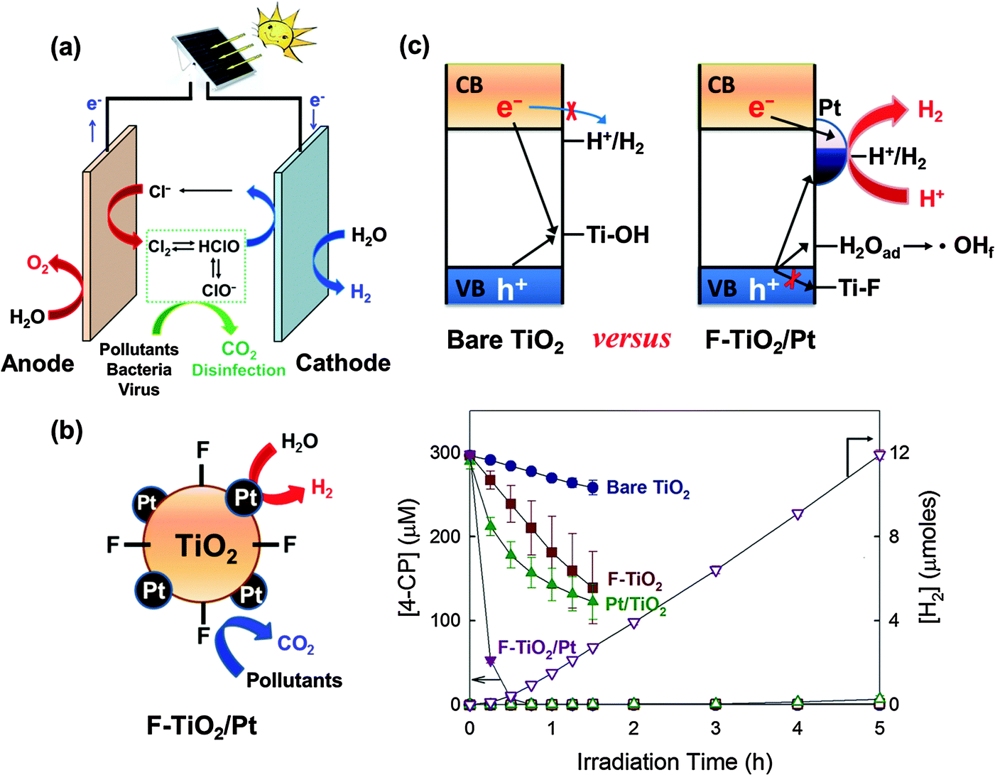 | ||
| Fig. 14 (a) Applications of charge transfer to the energy-water nexus. The photovoltaic-assisted electrochemical system can effectively remediate water pollutants and deactivate bacteria/virus in the presence of chloride at the anode, while chemical fuels (e.g., H2) can be produced at the cathode. (b and c) This dual function of the semiconductor can be achieved in particulate (suspension) systems (e.g., F-TiO2/Pt) without power assistance. Reproduced from ref. 250 with permission from The Royal Society of Chemistry. | ||
Recently, TiO2 the surface of which is modified with both fluoride (or phosphate) and platinum nanoparticle (F-TiO2/Pt or P-TiO2/Pt) has been successfully demonstrated for the dual function photocatalysis: simultaneous degradation of organic compounds and H2 production under a solar simulating condition (λ > 320 nm) (Fig. 14b).76,79,80 Surface fluorination (or phosphation) replaces the surface hydroxyl groups on TiO2, favoring the formation of unbound OH radicals (˙OHf) instead of surface-bound OH radicals (Ti–OH˙) (Fig. 14c).62,65,75,77,78,237 Since the surface-bound OH radicals (or surface-trapped holes) serve as a site of recombination with CB electrons, the fluoride substitution reduces the chance of recombination of CB electrons with the surface trapped holes on TiO2 particles. Meanwhile, surface platinization accelerates the electron transfer and further retards the charge pair recombination, thereby enhancing H2 production significantly.23,32,37,85,99,114,238 With these catalysts, the degradation of 4-CP and urea can be accompanied by the concurrent production of H2 (Fig. 14b). The synergistic effect greatly depends on the type of metal (Pt, Pd, Au, Ag, Cu, or Ni) and pH. The activity of F-TiO2/Pt gradually decreases with increasing pH, owing to the desorption of fluoride from the TiO2 surface. On the other hand, P-TiO2/Pt maintains the activity over a wide pH range because of the stability of the adsorbed phosphate, making the catalyst a more practical dual-function photocatalyst. Recently, the F-TiO2/Pt catalyst was further modified by the third component, graphene oxide (GO), to enhance the dual-functional photocatalytic activity.239 GO on TiO2 attracts electrons and facilitates the electron transfer to Pt. The positive effect of GO on the dual photocatalytic activity was observed only when Pt and surface fluoride are co-present. The photocatalytic activity of Pt/GO/TiO2-F (ternary system) for the simultaneous H2 production accompanied with the degradation of 4-CP was much higher than that of any binary-component photocatalysts, which confirmed the synergic role of the three components (i.e., GO, Pt, F).
6. Concluding remarks
Most semiconductor metal oxides including titania have limited photoactivity because of rapid charge recombination. The surface modification of semiconductor photocatalysts is a facile and soft method without reconstructing the solid lattice structure and has been widely attempted to improve the photocatalytic activity under UV and/or visible light irradiation. The modified surface of semiconductor critically influences the photo-induced CT behaviors at the interfacial region (particle/solution, particle/air, and particle/particle). Therefore, it is essential to understand how the modified surface properties control the primary factors involved in the overall photocatalysis. The photogenerated charge carriers follow various pathways which include recombination, trapping (at surface and bulk defect sites), transfer to a reservoir phase (e.g., Pt, graphene), transfer to bordering particles (of the same or different kind), and transfer to electron acceptors/donors in the electrolyte. For desirable photocatalytic reactions, the eventual transfer to electron acceptors or donors (i.e., target substrate) should be maximized, which can be controlled by modifying the surface properties. The effects of a specific modification method depend on many parameters and are specific to the kind of substrates, the characteristics of target reactions, and the experimental conditions. For example, a modified semiconductor optimized for a single-CT may not be good for a multiple-CT system (and vice versa). Therefore, it is usually not possible to generalize the effects of a specific modification method: even the same modified semiconductor may exhibit either a positive or a negative effect depending on the nature of the target photocatalytic conversion system. This implies that finding out “the best modification method” out of numerous possible ways of semiconductor modifications is not very meaningful. Each modification method and its related effects can be clearly defined only for a specific photocatalytic system. For example, it is not difficult to find out the published articles which claim to have developed a very efficient photocatalyst (hybrid or modified) based on a dye-discoloration measurement with an assumption that the particular photocatalyst would also be good for other photocatalytic conversion systems in general, which is actually not. The result could be different for other photocatalytic systems and even for a different dye.240 Therefore, the modification method of semiconductor photocatalysts should be cautiously chosen or designed on the basis of clear understanding of the characteristics of the target reaction. The dual-function photocatalysis, for example, aims to achieve the single CT for the pollutant oxidation part but the multiple-CT for H2 production part on the contrary, which is to control the transfer of holes and electrons in semiconductor particles in different ways. The development of appropriate modification methods to selectively control the CT behavior may realize such a goal.Acknowledgements
This research was financially supported by the Global Research Laboratory (GRL) Program (No. NRF-2014K1A1A2041044), the Global Frontier R&D Program on Center for Multiscale Energy System (2011-0031571), and KCAP (Sogang Univ.) (No. 2009-0093880), which were funded by the Korea Government (MSIP) through the National Research Foundation (NRF). H. P. is grateful to the Global Research Network Program (NRF-2014S1A2A2027802) for financial support.References
-
N. Serpone and E. Pelizzetti, Photocatalysis: Fundamentals and Applications, Wiley, New York, 1989 Search PubMed
.
-
C. A. Grimes, O. K. Varghese and S. Ranjan, Light, Water, Hydrogen: The Solar Generation of Hydrogen by Water Photoelectrolysis, Springer, New York, 2008 Search PubMed
-
R. Van de Krol and M. Gratzel, Photoelectrochemical Hydrogen Production, Springer, New York, 2012 Search PubMed
- M. R. Hoffmann, S. T. Martin, W. Choi and D. W. Bahnemann, Chem. Rev., 1995, 95, 69–96 CrossRef CAS
- A. Fujishima, X. T. Zhang and D. A. Tryk, Surf. Sci. Rep., 2008, 63, 515–582 CrossRef CAS
- M. J. Esswein and D. G. Nocera, Chem. Rev., 2007, 107, 4022–4047 CrossRef
- W. Choi, Catal. Surv. Asia, 2006, 10, 16–28 CrossRef CAS
- H. Park, Y. Park, Y. Kim and W. Choi, J. Photochem. Photobiol., C, 2012, 15, 1–20 CrossRef
-
On Solar Hydrogen & Nanotechnology, ed. L. Vayssieres, Wiley, Singapore, 2009 Search PubMed
-
J. Lee, J. Kim and W. Choi, in Aquatic Redox Chemistry, ed. P. G. Tratnyek, T. J. Grundl and S. B. Haderlein, American Chemical Society, Washington, 2011 Search PubMed
-
S. Licht, in Encyclopedia of Electrochemistry, ed. A. J. Bard and M. Stratmann, Wiley-VCH, Weinheim, 2002 Search PubMed
- N. Serpone, J. Phys. Chem. B, 2006, 110, 24287–24293 CrossRef CAS
- P. V. Kamat, J. Phys. Chem. B, 2002, 106, 7729–7744 CrossRef CAS
- T. L. Thompson and J. T. Yates, Jr., J. Phys. Chem. B, 2005, 109, 18230–18236 CrossRef CAS
- G. Hodes, J. Phys. Chem. C, 2008, 112, 17778–17787 CAS
- T. Tachikawa, M. Fujitsuka and T. Majima, J. Phys. Chem. C, 2007, 111, 5259–5275 CAS
- K. Maeda and K. Domen, J. Phys. Chem. Lett., 2010, 1, 2655–2661 CrossRef CAS
- J. A. Turner, Science, 1999, 285, 687–689 CrossRef CAS
- U. Kang and H. Park, Appl. Catal., B, 2013, 140–141, 233–240 CrossRef CAS
- T. H. Jeon, S. K. Choi, H. W. Jeong, S. Kim and H. Park, J. Electrochem. Sci. Technol., 2011, 2, 187–192 CrossRef CAS
- M. Tabata, K. Maeda, M. Higashi, D. L. Lu, T. Takata, R. Abe and K. Domen, Langmuir, 2010, 26, 9161–9165 CrossRef CAS PubMed
- H. W. Jeong, S.-Y. Choi, S. H. Hong, S. K. Lim, D. S. Han, A. Abdel-Wahab and H. Park, J. Phys. Chem. C, 2014, 118, 21331–21338 CAS
- J. Kim, C. W. Lee and W. Choi, Environ. Sci. Technol., 2010, 44, 6849–6854 CrossRef CAS PubMed
- J. Kim and W. Choi, Environ. Sci. Technol., 2011, 45, 3183–3184 CrossRef CAS
- H.-i. Kim, J. Kim, W. Kim and W. Choi, J. Phys. Chem. C, 2011, 115, 9797–9805 CAS
- H. Park, A. Bak, T. H. Jeon, S. Kim and W. Choi, Appl. Catal., B, 2012, 115–116, 74–80 CrossRef CAS
- C. Tagusagawa, A. Takagaki, A. Iguchi, K. Takanabe, J. N. Kondo, K. Ebitani, T. Tatsumi and K. Domen, Chem. Mater., 2010, 22, 3072–3078 CrossRef CAS
- A. Bak, W. Choi and H. Park, Appl. Catal., B, 2011, 110, 207–215 CrossRef CAS
- T. H. Jeon, W. Choi and H. Park, Phys. Chem. Chem. Phys., 2011, 13, 21392–21401 RSC
- M. Yoshida, T. Hirai, K. Maeda, N. Saito, J. Kubota, H. Kobayashi, Y. Inoue and K. Domen, J. Phys. Chem. C, 2010, 114, 15510–15515 CAS
- D. Yokoyama, T. Minegishi, K. Maeda, M. Katayama, J. Kubota, A. Yamada, M. Konagai and K. Domen, Electrochem. Commun., 2010, 12, 851–853 CrossRef CAS
- H. Park, W. Choi and M. R. Hoffmann, J. Mater. Chem., 2008, 18, 2379–2385 RSC
- Y. K. Kim and H. Park, Energy Environ. Sci., 2011, 4, 685–694 CAS
- G. Khan, S. K. Choi, S. Kim, S. K. Lim, J. S. Jang and H. Park, Appl. Catal., B, 2013, 142–143, 647–653 CrossRef CAS
- Y. Kim and H. Park, Appl. Catal., B, 2012, 125, 530–537 CrossRef CAS
- U. Kang, S. K. Choi, D. J. Ham, S. M. Ji, W. Choi, D. S. Han, A. Abdel-Wahab and H. Park, Energy Environ. Sci., 2015, 8, 2638–2643 CAS
- H. Park and W. Choi, J. Phys. Chem. B, 2003, 107, 3885–3890 CrossRef CAS
- K. Maeda, M. Higashi, D. L. Lu, R. Abe and K. Domen, J. Am. Chem. Soc., 2010, 132, 5858–5868 CrossRef CAS PubMed
- J. A. Seabold and K. S. Choi, Chem. Mater., 2011, 23, 1105–1112 CrossRef
- Y. Surendranath, M. Dinca and D. G. Nocera, J. Am. Chem. Soc., 2009, 131, 2615–2620 CrossRef PubMed
- S. K. Choi, W. Choi and H. Park, Phys. Chem. Chem. Phys., 2013, 15, 6499–6507 RSC
- D. K. Bediako, B. Lassalle-Kaiser, Y. Surendranath, J. Yano, V. K. Yachandra and D. G. Nocera, J. Am. Chem. Soc., 2012, 134, 6801–6809 CrossRef PubMed
- C. Tagusagawa, A. Takagaki, K. Takanabe, K. Ebitani, S. Hayashi and K. Domen, J. Catal., 2010, 270, 206–212 CrossRef
- S. J. Li, Z. C. Ma, J. Zhang, Y. S. Wu and Y. M. Gong, Catal. Today, 2008, 139, 109–112 CrossRef CAS
- A. Kudo and Y. Miseki, Chem. Soc. Rev., 2009, 38, 253–278 RSC
- E. R. Carraway, A. J. Hoffman and M. R. Hoffmann, Environ. Sci. Technol., 1994, 28, 786–793 CrossRef CAS PubMed
- C. Richard, J. Photochem. Photobiol., A, 1993, 72, 179–182 CrossRef CAS
- Y. Mao, C. Schoneich and K. D. Asmus, J. Phys. Chem., 1991, 95, 10080–10089 CrossRef CAS
- R. B. Draper and M. A. Fox, Langmuir, 1990, 6, 1396–1402 CrossRef CAS
- S. Kim and W. Choi, Environ. Sci. Technol., 2002, 36, 2019–2025 CrossRef CAS PubMed
- M. C. Lee and W. Choi, J. Phys. Chem. B, 2002, 106, 11818–11822 CrossRef CAS
- S. Chen and L.-W. Wang, Chem. Mater., 2012, 24, 3659–3666 CrossRef CAS
- W. Choi, A. Termin and M. R. Hoffmann, J. Phys. Chem., 1994, 98, 13669–13679 CrossRef
- W. Choi, A. Termin and M. R. Hoffmann, Angew. Chem., Int. Ed. Engl., 1994, 33, 1091–1092 CrossRef
- M. Mrowetz, W. Balcerski, A. J. Colussi and M. R. Hoffmann, J. Phys. Chem. B, 2004, 108, 17269–17273 CrossRef
- S. Kim, S. J. Hwang and W. Choi, J. Phys. Chem. B, 2005, 109, 24260–24267 CrossRef CAS PubMed
- Y. Park, W. Kim, H. Park, T. Tachikwawa, T. Majima and W. Choi, Appl. Catal., B, 2009, 91, 355–361 CrossRef CAS
- W. Kim, T. Tachikawa, H. Kim, N. Lakshminarasimhan, P. Murugan, H. Park, T. Majima and W. Choi, Appl. Catal., B, 2014, 147, 642–650 CrossRef CAS
- W. Choi, S. J. Hong, Y. S. Chang and Y. Cho, Environ. Sci. Technol., 2000, 34, 4810–4815 CrossRef CAS
- C. X. Zhang, T. L. Sun and X. M. Sun, Environ. Sci. Technol., 2011, 45, 4756–4762 CrossRef CAS PubMed
- H. Park and W. Choi, J. Phys. Chem. B, 2005, 109, 11667–11674 CrossRef PubMed
- M. S. Vohra, S. Kim and W. Choi, J. Photochem. Photobiol., A, 2003, 160, 55–60 CrossRef CAS
- G. Zhang, W. Choi, S. H. Kim and S. B. Hong, J. Hazard. Mater., 2011, 188, 198–205 CrossRef CAS PubMed
- P. Chin, C. S. Grant and D. F. Ollis, Appl. Catal., B, 2009, 87, 220–229 CrossRef CAS
- J. S. Park and W. Choi, Langmuir, 2004, 20, 11523–11527 CrossRef CAS PubMed
- H. Haick and Y. Paz, J. Phys. Chem. B, 2001, 105, 3045–3051 CrossRef CAS
- S. K. Lee, S. McIntyre and A. Mills, J. Photochem. Photobiol., A, 2004, 162, 203–206 CrossRef CAS
- J. S. Park and W. Choi, Chem. Lett., 2005, 34, 1630–1631 CrossRef CAS
- T. Tatsuma, W. Kubo and A. Fujishima, Langmuir, 2002, 18, 9632–9634 CrossRef CAS
- T. Tatsuma, S. Tachibana and A. Fujishima, J. Phys. Chem. B, 2001, 105, 6987–6992 CrossRef CAS
- T. Tatsuma, S. Tachibana, T. Miwa, D. A. Tryk and A. Fujishima, J. Phys. Chem. B, 1999, 103, 8033–8035 CrossRef CAS
- S. M. Cho and W. Choi, J. Photochem. Photobiol., A, 2001, 143, 221–228 CrossRef
- P. Chin, G. W. Roberts and D. F. Ollis, Ind. Eng. Chem. Res., 2007, 46, 7598–7604 CrossRef CAS
- W. Kim, T. Tachikawa, G. Moon, T. Majima and W. Choi, Angew. Chem., Int. Ed., 2014, 53, 14036–14041 CrossRef CAS PubMed
- H. Park and W. Choi, J. Phys. Chem. B, 2004, 108, 4086–4093 CrossRef CAS
- J. Kim and W. Choi, Appl. Catal., B, 2011, 106, 39–45 CAS
- H. Kim and W. Choi, Appl. Catal., B, 2006, 69, 127–132 CrossRef
- J. Kim, W. Choi and H. Park, Res. Chem. Intermed., 2010, 36, 127–140 CrossRef CAS
- J. Kim, J. Lee and W. Choi, Chem. Commun., 2008, 756–758 RSC
- J. Kim, D. Monllor-Satoca and W. Choi, Energy Environ. Sci., 2012, 5, 7647–7656 CAS
- C. Minero, G. Mariella, V. Maurino and E. Pelizzetti, Langmuir, 2000, 16, 2632–2641 CrossRef CAS
- V. Maurino, C. Minero, G. Mariella and E. Pelizzetti, Chem. Commun., 2005, 2627–2629 RSC
- M. Mrowetz and E. Selli, Phys. Chem. Chem. Phys., 2005, 7, 1100–1102 RSC
- T. Ohno, F. Tanigawa, K. Fujihara, S. Izumi and M. Matsumura, J. Photochem. Photobiol., A, 1998, 118, 41–44 CrossRef CAS
- H. Park, J. Lee and W. Choi, Catal. Today, 2006, 111, 259–265 CrossRef CAS
- R. Abe, M. Higashi and K. Domen, J. Am. Chem. Soc., 2010, 132, 11828–11829 CrossRef CAS PubMed
- S. S. K. Ma, T. Hisatomi, K. Maeda, Y. Moriya and K. Domen, J. Am. Chem. Soc., 2012, 134, 19993–19996 CrossRef CAS PubMed
- H. Kim, H.-Y. Yoo, S. Hong, S. Lee, B.-S. Park, H. Park, C. Lee and J. Lee, Appl. Catal., B, 2015, 162, 515–523 CrossRef CAS
- D. F. Evans and M. W. Upton, J. Chem. Soc., Dalton Trans., 1985, 1141–1145 RSC
- S. T. Martin, A. T. Lee and M. R. Hoffmann, Environ. Sci. Technol., 1995, 29, 2567–2573 CrossRef CAS PubMed
- E. Pelizzetti, V. Carlin, C. Minero and M. Gratzel, New J. Chem., 1991, 15, 351–359 CAS
- W. V. Steele and E. H. Appelman, J. Chem. Thermodyn., 1982, 14, 337–344 CrossRef CAS
- R. R. Ozer and J. L. Ferry, Environ. Sci. Technol., 2001, 35, 3242–3246 CrossRef CAS PubMed
- I. A. Weinstock, Chem. Rev., 1998, 98, 113–170 CrossRef CAS PubMed
- J. Lee, J. Kim and W. Choi, Environ. Sci. Technol., 2007, 41, 3335–3340 CrossRef CAS PubMed
- J. Ryu and W. Choi, Environ. Sci. Technol., 2006, 40, 7034–7039 CrossRef CAS PubMed
- Y. Cho, W. Choi, C. H. Lee, T. Hyeon and H. I. Lee, Environ. Sci. Technol., 2001, 35, 966–970 CrossRef CAS PubMed
- E. Bae and W. Choi, Environ. Sci. Technol., 2002, 37, 147–152 CrossRef
- S. Kim and W. Choi, J. Phys. Chem. B, 2002, 106, 13311–13317 CrossRef CAS
- C. D. Vecitis, H. Park, J. Cheng, B. T. Mader and M. R. Hoffmann, Front. Environ. Sci. Eng. China, 2009, 3, 129–151 CrossRef CAS
- H. Park, C. D. Vecitis, J. Cheng, W. Choi, B. T. Mader and M. R. Hoffmann, J. Phys. Chem. A, 2009, 113, 690–696 CrossRef CAS PubMed
- E. Szajdzinska-Pietek and J. L. Gebicki, Res. Chem. Intermed., 2000, 26, 897–912 CrossRef CAS
- H. Park, C. D. Vecitis, J. Cheng, N. F. Dalleska, B. T. Mader and M. R. Hoffmann, Photochem. Photobiol.
Sci., 2011, 10, 1945–1953 CAS
- H. Kyung, J. Lee and W. Choi, Environ. Sci. Technol., 2005, 39, 2376–2382 CrossRef CAS PubMed
- S. Kim and H. Park, RSC Adv., 2013, 3, 17551–17558 RSC
- W. Choi and M. R. Hoffmann, Environ. Sci. Technol., 1995, 29, 1646–1654 CrossRef CAS PubMed
- W. Choi and M. R. Hoffmann, Environ. Sci. Technol., 1997, 31, 89–95 CrossRef CAS
- B. Kraeutler and A. J. Bard, J. Am. Chem. Soc., 1978, 100, 4317–4318 CrossRef CAS
- M. Jakob, H. Levanon and P. V. Kamat, Nano Lett., 2003, 3, 353–358 CrossRef CAS
- W. Choi, J. Lee, S. Kim, S. Hwang, M. C. Lee and T. K. Lee, J. Ind. Eng. Chem., 2003, 9, 96–101 CAS
- J. Lee, W. Choi and J. Yoon, Environ. Sci. Technol., 2005, 39, 6800–6807 CrossRef CAS PubMed
- I. Mikami, S. Aoki and Y. Miura, Chem. Lett., 2010, 39, 704–705 CrossRef CAS
- L. A. Pretzer, P. J. Carlson and J. E. Boyd, J. Photochem. Photobiol., A, 2008, 200, 246–253 CrossRef CAS
- J. Lee and W. Choi, Environ. Sci. Technol., 2004, 38, 4026–4033 CrossRef CAS PubMed
- J. Lee and W. Choi, J. Phys. Chem. B, 2005, 109, 7399–7406 CrossRef CAS PubMed
- J. Lee, H. Park and W. Choi, Environ. Sci. Technol., 2002, 36, 5462–5468 CrossRef CAS PubMed
- W. Zhao, C. Chen, X. Li, J. Zhao, H. Hidaka and N. Serpone, J. Phys. Chem. B, 2002, 106, 5022–5028 CrossRef CAS
- N. Z. Muradov, Sol. Energy, 1994, 52, 283–288 CrossRef CAS
- D. Hufschmidt, D. Bahnemann, J. J. Testa, C. A. Emilio and M. I. Litter, J. Photochem. Photobiol., A, 2002, 148, 223–231 CrossRef CAS
- B. Sun, V. Vorontsov and P. G. Smirniotis, Langmuir, 2003, 19, 3151–3156 CrossRef CAS
- M. Trillas, J. Peral and X. Domenech, Appl. Catal., B, 1995, 5, 377–387 CrossRef CAS
- B. H. J. Bielski, D. E. Cabelli, R. L. Arudi and A. B. Ross, J. Phys. Chem. B, 1985, 14, 1041–1100 CAS
- A. J. Cowan, J. W. Tang, W. H. Leng, J. R. Durrant and D. R. Klug, J. Phys. Chem. C, 2010, 114, 4208–4214 CAS
- H. Gerischer and A. Heller, J. Phys. Chem., 1991, 95, 5261–5267 CrossRef CAS
- W. Choi, J. Yeo, J. Ryu, T. Tachikawa and T. Majima, Environ. Sci. Technol., 2010, 44, 9099–9104 CrossRef CAS PubMed
- J. Ryu and W. Choi, Environ. Sci. Technol., 2004, 38, 2928–2933 CrossRef CAS PubMed
- J. Ryu and W. Choi, Environ. Sci. Technol., 2007, 41, 6313–6314 CrossRef CAS
- D. Monllor-Satoca, T. Tachikawa, T. Majima and W. Choi, Environ. Sci. Technol., 2011, 45, 2030–2031 CrossRef CAS
- D. Monllor-Satoca, R. Gomez and W. Choi, Environ. Sci. Technol., 2012, 46, 5519–5527 CrossRef CAS PubMed
- H. Lee and W. Choi, Environ. Sci. Technol., 2002, 36, 3872–3878 CrossRef CAS PubMed
- C. Kormann, D. W. Bahnemann and M. R. Hoffmann, Environ. Sci. Technol., 1988, 22, 798–806 CrossRef CAS PubMed
- X. Z. Li, C. C. Chen and J. C. Zhao, Langmuir, 2001, 17, 4118–4122 CrossRef CAS
- M. Teranishi, S. Naya and H. Tada, J. Am. Chem. Soc., 2010, 132, 7850–7851 CrossRef CAS PubMed
- J. Yi, C. Bahrini, C. Schoemaecker, C. Fittschen and W. Choi, J. Phys. Chem. C, 2012, 116, 10090–10097 CAS
- N. M. Dimitrijevic, B. K. Vijayan, O. G. Poluektov, T. Rajh, K. A. Gray, H. Y. He and P. Zapol, J. Am. Chem. Soc., 2011, 133, 3964–3971 CrossRef CAS PubMed
- E. Fujita, Coord. Chem. Rev., 1999, 185–186, 373–384 CrossRef CAS
- T. Yui, A. Kan, C. Saitoh, K. Koike, T. Ibusuki and O. Ishitani, ACS Appl. Mater. Interfaces, 2011, 3, 2594–2600 CAS
- S. K. Choi, U. Kang, S. Lee, D. J. Ham, S. M. Ji and H. Park, Adv. Energy Mater., 2014, 4, 1301614 Search PubMed
- H. Park, H.-H. Qu, A. J. Colussi and M. R. Hoffmann, J. Phys. Chem. A, 2015, 119, 4658–4666 CrossRef CAS PubMed
- J. R. Bolton, S. J. Strickler and J. S. Connolly, Nature, 1985, 316, 495–500 CrossRef CAS
- J. Greeley, T. F. Jaramillo, J. Bonde, I. B. Chorkendorff and J. K. Norskov, Nat. Mater., 2006, 5, 909–913 CrossRef CAS PubMed
- S. Trasatti, J. Electroanal. Chem., 1972, 39, 163–184 CrossRef CAS
- T. Hisatomi, K. Miyazaki, K. Takanabe, K. Maeda, J. Kubota, Y. Sakata and K. Domen, Chem. Phys. Lett., 2010, 486, 144–146 CrossRef CAS
- K. Maeda and K. Domen, Chem. Mater., 2010, 22, 612–623 CrossRef CAS
- Y. Park, S. H. Kang and W. Choi, Phys. Chem. Chem. Phys., 2011, 13, 9425–9431 RSC
- R. Leary and A. Westwood, Carbon, 2011, 49, 741–772 CrossRef CAS
- G. H. Moon, Y. Park, W. Kim and W. Choi, Carbon, 2011, 49, 3454–3462 CrossRef CAS
- L.-L. Tan, S.-P. Chai and A. R. Mohamed, ChemSusChem, 2012, 5, 1868–1882 CrossRef CAS PubMed
- H.-i. Kim, G. H. Moon, D. Monllor-Satoca, Y. Park and W. Choi, J. Phys. Chem. C, 2012, 116, 1535–1543 CAS
- G. Moon, D. Kim, H. Kim, A. D. Bokare and W. Choi, Environ. Sci. Technol. Lett., 2014, 1, 185–190 CrossRef CAS
- G. Moon, W. Kim, A. D. Bokare, N. Sung and W. Choi, Energy Environ. Sci., 2014, 7, 4023–4028 CAS
- H.-i. Kim, S. Kim, J. Kang and W. Choi, J. Catal., 2014, 309, 49–57 CrossRef CAS
- A. J. Hoffman, E. R. Carraway and M. R. Hoffmann, Environ. Sci. Technol., 1994, 28, 776–785 CrossRef CAS PubMed
- W. Kim, T. Seok and W. Choi, Energy Environ. Sci., 2012, 5, 6066–6070 CAS
- A. J. Bard and M. A. Fox, Acc. Chem. Res., 1995, 28, 141–145 CrossRef CAS
- Y. Park, K. J. McDonald and K.-S. Choi, Chem. Soc. Rev., 2013, 42, 2321–2337 RSC
- K. Sivula, F. Le Formal and M. Gratzel, ChemSusChem, 2011, 4, 432–449 CrossRef CAS PubMed
- F. X. Yin, K. Takanabe, M. Katayama, J. Kubota and K. Domen, Electrochem. Commun., 2010, 12, 1177–1179 CrossRef CAS
- W. Kim, T. Tachikawa, D. Monllor-Satoca, H.-i. Kim, T. Majima and W. Choi, Energy Environ. Sci., 2013, 6, 3732–3739 CAS
- N. Lakshminarasimhan, W. Kim and W. Choi, J. Phys. Chem. C, 2008, 112, 20451–20457 CAS
- Y. Park, W. Kim, D. Monllor-Satoca, T. Tachikawa, T. Majima and W. Choi, J. Phys. Chem. Lett., 2013, 4, 189–194 CrossRef CAS PubMed
- N. Lakshminarasimhan, E. Bae and W. Choi, J. Phys. Chem. C, 2007, 111, 15244–15250 CAS
- S. K. Choi, S. Kim, S. K. Lim and H. Park, J. Phys. Chem. C, 2010, 114, 16475–16480 CAS
- T. H. Jeon, W. Choi and H. Park, J. Phys. Chem. C, 2011, 115, 7134–7142 CAS
- J. S. Jang, S. H. Choi, H. Park, W. Choi and J. S. Lee, J. Nanosci. Nanotechnol., 2006, 6, 3642–3646 CrossRef CAS PubMed
- S. K. Choi, S. Kim, J. Ryu, S. K. Lim and H. Park, Photochem. Photobiol. Sci., 2012, 11, 1437–1444 CAS
- H. W. Jeong, T. H. Jeon, J. S. Jang, W. Choi and H. Park, J. Phys. Chem. C, 2013, 117, 9104–9112 CAS
- D. Zhao, C. C. Chen, C. L. Yu, W. H. Ma and J. C. Zhao, J. Phys. Chem. C, 2009, 113, 13160–13165 CAS
- S. Biswas, M. F. Hossain, M. Shahjahan, K. Takahashi, T. Takahashi and A. Fujishima, J. Vac. Sci. Technol., A, 2009, 27, 880–884 CAS
- W. Smith and Y. P. Zhao, J. Phys. Chem. C, 2008, 112, 19635–19641 CAS
- L. X. Cao, F. J. Spiess, A. M. Huang, S. L. Suib, T. N. Obee, S. O. Hay and J. D. Freihaut, J. Phys. Chem. B, 1999, 103, 2912–2917 CrossRef CAS
- Y. Cao, X. T. Zhang, W. S. Yang, H. Du, Y. B. Bai, T. J. Li and J. N. Yao, Chem. Mater., 2000, 12, 3445–3448 CrossRef CAS
- U. Scharf, M. Schramlmarth, A. Wokaun and A. Baiker, J. Chem. Soc., Faraday Trans., 1991, 87, 3299–3307 RSC
- J. H. Fang, J. W. Wu, X. M. Lu, Y. C. Shen and Z. H. Lu, Chem. Phys. Lett., 1997, 270, 145–151 CrossRef CAS
- X. C. Shen, Z. L. Zhang, B. Zhou, J. Peng, M. Xie, M. Zhang and D. W. Pang, Environ. Sci. Technol., 2008, 42, 5049–5054 CrossRef CAS PubMed
- H. Park, Y. K. Kim and W. Choi, J. Phys. Chem. C, 2011, 115, 6141–6148 CAS
-
J. S. Jang and H. Park, in Materials and Processes for Solar Fuel Production, ed. R. Subramanian, B. Viswanathan and J. S. Lee, Springer, New York, 2014 Search PubMed
- H. Tada, A. Kokubu, M. Iwasaki and S. Ito, Langmuir, 2004, 20, 4665–4670 CrossRef CAS PubMed
- W. Smith and Y. P. Zhao, Catal. Commun., 2009, 10, 1117–1121 CrossRef CAS
- B. Tryba, M. Piszcz and A. W. Morawski, Int. J. Photoenergy, 2009, 2009, 297319 CrossRef
- J. Papp, S. Soled, K. Dwight and A. Wold, Chem. Mater., 1994, 6, 496–500 CrossRef CAS
- H. Park, K. Y. Kim and W. Choi, Chem. Commun., 2001, 281–282 RSC
- H. Park, K. Y. Kim and W. Choi, J. Phys. Chem. B, 2002, 106, 4775–4781 CrossRef CAS
- R. Abe, H. Takami, N. Murakami and B. Ohtani, J. Am. Chem. Soc., 2008, 130, 7780–7781 CrossRef CAS PubMed
- D. X. Shi, Y. Q. Feng and S. H. Zhong, Catal. Today, 2004, 98, 505–509 CrossRef CAS
- C. Y. Wang, H. M. Shang, T. Ying, T. S. Yuan and G. W. Zhang, Sep. Purif. Technol., 2003, 32, 357–362 CrossRef CAS
- A. Kumar and A. K. Jain, J. Photochem. Photobiol., A, 2003, 156, 207–218 CrossRef CAS
- Y. Bessekhouad, N. Chaoui, M. Trzpit, N. Ghazzal, D. Robert and J. V. Weber, J. Photochem. Photobiol., A, 2006, 183, 218–224 CrossRef CAS
- H. B. Yin, Y. Wada, T. Kitamura, T. Sakata, H. Mori and S. Yanagida, Chem. Lett., 2001, 334–335 CrossRef CAS
- T. A. Khalyavka, E. I. Kapinus and T. I. Viktorova, Pol. J. Chem., 2008, 82, 107–112 CAS
- A. Kumar and A. K. Jain, J. Mol. Catal. A: Chem., 2001, 165, 265–273 CrossRef CAS
- P. A. Sant and P. V. Kamat, Phys. Chem. Chem. Phys., 2002, 4, 198–203 RSC
- H. Matsumoto, T. Matsunaga, T. Sakata, H. Mori and H. Yoneyama, Langmuir, 1995, 11, 4283–4287 CrossRef CAS
- H. Tada, T. Mitsui, T. Kiyonaga, T. Akita and K. Tanaka, Nat. Mater., 2006, 5, 782–786 CrossRef CAS PubMed
- N. Nishimura, B. Raphael, K. Maeda, L. Le Gendre, R. Abe, J. Kubota and K. Domen, Thin Solid Films, 2010, 518, 5855–5859 CrossRef CAS
- R. Ohnishi, M. Katayama, K. Takanabe, J. Kubota and K. Domen, Electrochim. Acta, 2010, 55, 5393–5400 CrossRef CAS
- T. Hisatomi, M. Otani, K. Nakajima, K. Teramura, Y. Kako, D. L. Lu, T. Takata, J. N. Kondo and K. Domen, Chem. Mater., 2010, 22, 3854–3861 CrossRef CAS
- M. Tabata, K. Maeda, T. Ishihara, T. Minegishi, T. Takata and K. Domen, J. Phys. Chem. C, 2010, 114, 11215–11220 CAS
- H.-i. Kim, D. Monllor-Satoca, W. Kim and W. Choi, Energy Environ. Sci., 2015, 8, 247–257 CAS
- Y. Park, S. H. Lee, S. O. Kang and W. Choi, Chem. Commun., 2010, 46, 2477–2479 RSC
- S. K. Choi, H. S. Yang, J. H. Kim and H. Park, Appl. Catal., B, 2012, 121–122, 206–213 CrossRef CAS
- V. H. Houlding and M. Gratzel, J. Am. Chem. Soc., 1983, 105, 5695–5696 CrossRef CAS
- S. Ikeda, C. Abe, T. Torimoto and B. Ohtani, J. Photochem. Photobiol., A, 2003, 160, 61–67 CrossRef CAS
- G. Kim and W. Choi, Appl. Catal., B, 2010, 100, 77–83 CrossRef CAS
- S. Kim and W. Choi, J. Phys. Chem. B, 2005, 109, 5143–5149 CrossRef CAS PubMed
- J. M. Notestein, E. Iglesia and A. Katz, Chem. Mater., 2007, 19, 4998–5005 CrossRef CAS
- Y. Park, N. J. Singh, K. S. Kim, T. Tachikawa, T. Majima and W. Choi, Chem. – Eur. J., 2009, 15, 10843–10850 CrossRef CAS PubMed
- P. Persson, R. Bergstrom and S. Lunell, J. Phys. Chem. B, 2000, 104, 10348–10351 CrossRef CAS
- Y. S. Seo, C. Lee, K. H. Lee and K. B. Yoon, Angew. Chem., Int. Ed., 2005, 44, 910–913 CrossRef CAS PubMed
- M. Yang, D. W. Thompson and G. J. Meyer, Inorg. Chem., 2002, 41, 1254–1262 CrossRef CAS PubMed
- G. Zhang and W. Choi, Chem. Commun., 2012, 48, 10621–10623 RSC
- W. R. Duncan and O. V. Prezhdo, Annu. Rev. Phys. Chem., 2007, 58, 143–184 CrossRef CAS PubMed
- E. Bae and W. Choi, J. Phys. Chem. B, 2006, 110, 14792–14799 CrossRef CAS PubMed
- E. Bae, W. Choi, J. W. Park, H. S. Shin, S. B. Kim and J. S. Lee, J. Phys. Chem. B, 2004, 108, 14093–14101 CrossRef CAS
- H. Park and W. Choi, Langmuir, 2006, 22, 2906–2911 CrossRef CAS PubMed
- H. Park, E. Bae, J. J. Lee, J. Park and W. Choi, J. Phys. Chem. B, 2006, 110, 8740–8749 CrossRef CAS PubMed
- W. Kim, T. Tachikawa, T. Majima, C. Li, H.-J. Kim and W. Choi, Energy Environ. Sci., 2010, 3, 1789–1795 CAS
- D. P. Arnold and J. Blok, Coord. Chem. Rev., 2004, 248, 299–319 CrossRef CAS
-
Photochemistry of Polypyridine and Porphyrin Complexes, ed. K. Kalyanasundaram, Academic Press, San Diego, 1992 Search PubMed
- A. G. Agrios, K. A. Gray and E. Weitz, Langmuir, 2004, 20, 5911–5917 CrossRef CAS PubMed
- T. Tachikawa, S. Tojo, M. Fujitsuka and T. Majima, J. Phys. Chem. B, 2004, 108, 5859–5866 CrossRef CAS
- G. Kim, S.-H. Lee and W. Choi, Appl. Catal., B, 2015, 162, 463–469 CrossRef CAS
- Y. Cho, H. Kyung and W. Choi, Appl. Catal., B, 2004, 52, 23–32 CrossRef CAS
- Y. K. Kim, S. Lee, J. Ryu and H. Park, Appl. Catal., B, 2015, 163, 584–590 CrossRef CAS
- H. Wender, A. F. Feil, L. B. Diaz, C. S. Ribeiro, G. J. Machado, P. Migowski, D. E. Weibel, J. Dupont and S. R. Teixeira, ACS Appl. Mater. Interfaces, 2011, 3, 1359–1365 CAS
- M. C. Wu, J. Hiltunen, A. Sapi, A. Avila, W. Larsson, H. C. Liao, M. Huuhtanen, G. Toth, A. Shchukarev, N. Laufer, A. Kukovecz, Z. Konya, J. P. Mikkola, R. Keiski, W. F. Su, Y. F. Chen, H. Jantunen, P. M. Ajayan, R. Vajtai and K. Kordas, ACS Nano, 2011, 5, 5025–5030 CrossRef CAS PubMed
- X. Y. Zhang, H. P. Li, X. L. Cui and Y. H. Lin, J. Mater. Chem., 2010, 20, 2801–2806 RSC
- B. Zielinska, E. Borowiak-Palen and R. J. Kalenczuk, Int. J. Hydrogen Energy, 2008, 33, 1797–1802 CrossRef CAS
- H. Park, A. Bak, A. Y. Ahn, J. Choi and M. R. Hoffmann, J. Hazard. Mater., 2012, 211–212, 47–54 CrossRef CAS PubMed
- H. Park, C. D. Vecitis, W. Choi, O. Weres and M. R. Hoffmann, J. Phys. Chem. C, 2008, 112, 885–889 CAS
- H. Park, C. D. Vecitis and M. R. Hoffmann, J. Phys. Chem. A, 2008, 112, 7616–7626 CrossRef CAS PubMed
- H. Park, C. D. Vecitis and M. R. Hoffmann, J. Phys. Chem. C, 2009, 113, 7935–7945 CAS
- J. Kim, W. J. K. Choi, J. Choi, M. R. Hoffmann and H. Park, Catal. Today, 2013, 199, 2–7 CrossRef CAS
- S. Y. Yang, W. Choi and H. Park, ACS Appl. Mater. Interfaces, 2015, 7, 1907–1914 CAS
-
T. Sakata, in Photocatalysis: Fundamentals and Applications, ed. N. Serpone and E. Pelizzetti, John Wiley & Sons, New York, 1989 Search PubMed
- E. Borgarello, J. Kiwi, E. Pelizzetti, M. Visca and M. Gratzel, Nature, 1981, 289, 158–160 CrossRef CAS
- H. Park and W. Choi, Catal. Today, 2005, 101, 291–297 CrossRef CAS
- J. Kim, Y. Park and H. Park, Int. J. Photoenergy, 2014, 2014, 324859 Search PubMed
- Y.-J. Cho, H.-i. Kim, S. Lee and W. Choi, J. Catal., 2015, 330, 387–395 CrossRef CAS
- S. Bae, S. Kim, S. Lee and W. Choi, Catal. Today, 2014, 224, 21–28 CrossRef CAS
- M. Sadeghi, W. Liu, T. G. Zhang, P. Stavropoulos and B. Levy, J. Phys. Chem., 1996, 100, 19466–19474 CrossRef CAS
- G. Khan, Y. K. Kim, S. K. Choi, D. S. Han, A. Abdel-Wahab and H. Park, Bull. Korean Chem. Soc., 2013, 34, 1137–1144 CrossRef CAS
- J. Choi, H. Park and M. R. Hoffmann, J. Phys. Chem. C, 2010, 114, 783–792 CAS
- J. N. Kondo, D. Nishioka, H. Yamazaki, J. Kubota, K. Domen and T. Tatsumi, J. Phys. Chem. C, 2010, 114, 20107–20113 CAS
- M. Katayama, D. Yokoyama, Y. Maeda, Y. Ozaki, M. Tabata, Y. Matsumoto, A. Ishikawa, J. Kubota and K. Domen, Mater. Sci. Eng., B, 2010, 173, 275–278 CrossRef CAS
- G. L. Chiarello, E. Selli and L. Forni, Appl. Catal., B, 2008, 84, 332–339 CrossRef CAS
- J. S. Jang, S. H. Choi, H. G. Kim and J. S. Lee, J. Phys. Chem. C, 2008, 112, 17200–17205 CAS
- C.-W. Tsai, H. M. Chen, R.-S. Liu, K. Asakura and T.-S. Chan, J. Phys. Chem. C, 2011, 115, 10180–10186 CAS
- M. Mrowetz and E. Selli, New J. Chem., 2006, 30, 108–114 RSC
- J. Kim and W. Choi, Energy Environ. Sci., 2010, 3, 1042–1045 CAS
- Y. Cho, H. Park and W. Choi, J. Photochem. Photobiol., A, 2004, 165, 43–50 CrossRef CAS
- J. Ryu and W. Choi, Environ. Sci. Technol., 2008, 42, 294–300 CrossRef CAS PubMed
| This journal is © The Royal Society of Chemistry 2016 |