
 Open Access Article
 This Open Access Article is licensed under a
 Creative Commons Attribution 3.0 Unported Licence
Exceptional hydrogen permeation of all-ceramic composite robust membranes based on BaCe0.65Zr0.20Y0.15O3−δ and Y- or Gd-doped ceria†
Elena
Rebollo
a,
Cecilia
Mortalò
*a,
Sonia
Escolástico
b,
Stefano
Boldrini
a,
Simona
Barison
a,
José M.
Serra
 b and
Monica
Fabrizio
a
b and
Monica
Fabrizio
a
aIstituto per l'Energetica e le Interfasi- Consiglio Nazionale delle Ricerche CNR-IENI Corso Stati Uniti 4, 35127, Padova, Italy. E-mail: c.mortalo@ieni.cnr.it
bInstituto de Tecnología Química (Universidad Politécnica de Valencia-Consejo Superior de Investigaciones Cientifícas), Av. Los Naranjos s/n, E-46022 Valencia, Spain
First published on 15th October 2015
Abstract
Mixed proton and electron conductor ceramic composites were examined as hydrogen separation membranes at moderate temperatures (higher than 500 °C). In particular, dense ceramic composites of BaCe0.65Zr0.20Y0.15O3−δ (BCZ20Y15) and Ce0.85M0.15O2−δ (M = Y and Gd, hereafter referred to as YDC15 and GDC15), as protonic and electronic conducting phases respectively, were successfully prepared and tested as hydrogen separation membranes. The mixture of these oxides improved both chemical and mechanical stability and increased the electronic conductivity in dual-phase ceramic membranes. The synthetic method and sintering conditions were optimized to obtain dense and crack free symmetric membranes. The addition of ZnO as a sintering aid allowed achieving robust and dense composites with homogeneous grain distribution. The chemical compatibility between the precursors and the influence of membrane composition on electrical properties and H2 permeability performances were thoroughly investigated. The highest permeation flux was attained for the 50![[thin space (1/6-em)]](https://www.rsc.org/images/entities/char_2009.gif) :50 volume ratio BCZ20Y15–GDC15 membrane when the feed and the sweep sides of the membrane were hydrated, reaching values of 0.27 mL min−1 cm−2 at 755 °C on a 0.65 mm thick membrane sample, currently one of the highest H2 fluxes obtained for bulk mixed protonic–electronic membranes. Increasing the temperature to 1040 °C, increased the hydrogen flux up to 2.40 mL min−1 cm−2 when only the sweep side was hydrated. The H2 separation process is attributed to two cooperative mechanisms, i.e. proton transport through the membrane and H2 production via the water splitting reaction coupled with oxygen ion transport. Moreover, these composite systems demonstrated a very good chemical stability under a CO2-rich atmosphere such as catalytic reactors for hydrogen generation.
:50 volume ratio BCZ20Y15–GDC15 membrane when the feed and the sweep sides of the membrane were hydrated, reaching values of 0.27 mL min−1 cm−2 at 755 °C on a 0.65 mm thick membrane sample, currently one of the highest H2 fluxes obtained for bulk mixed protonic–electronic membranes. Increasing the temperature to 1040 °C, increased the hydrogen flux up to 2.40 mL min−1 cm−2 when only the sweep side was hydrated. The H2 separation process is attributed to two cooperative mechanisms, i.e. proton transport through the membrane and H2 production via the water splitting reaction coupled with oxygen ion transport. Moreover, these composite systems demonstrated a very good chemical stability under a CO2-rich atmosphere such as catalytic reactors for hydrogen generation.
Broader contextH2-selective membranes represent an appealing option to recover hydrogen from low-quality gas e.g. from biomass. Although a range of H2-selective materials has been developed, none of these have been able to rival Pd or its alloys in terms of efficiency. Nevertheless, the specific benefit from H2 permeation membranes based on ceramic mixed proton and electron conductor oxides (MPEC) is that they allow the water-gas shift reaction at much higher temperatures than in a conventional reactor, maintaining the gas hot in the integrated system. This unique characteristic can be crucial for adopting an alternative to conventional power plants for sustainable electricity generation. Among the MPEC ceramic membranes tested so far, the dense composites of BaCe0.65Zr0.20Y0.15O3−δ and Ce0.85Gd0.15O2−δ (50:50 volume ratio) investigated in this paper showed hydrogen permeation values among the highest achieved for bulk mixed protonic–electronic membranes so far (0.27 mL min−1 cm−2 at 755 °C and 2.40 mL min−1 cm−2 at 1040 °C). The transport mechanism has been investigated by permeation studies, revealing concurrent proton transport across the membrane and H2 production by water splitting, thus providing an extra H2 flow. The robustness of these membranes was also verified under operating conditions (e.g. in a CO2 rich environment).
|
Introduction
Nowadays, industrial production of hydrogen is mainly conducted by steam reforming of methane (SMR). This process is highly endothermic, limited by equilibrium and needs subsequent hydrogen separation procedures that require high capital costs and are energy intensive (such as pressure swing adsorption and cryogenic distillation).1–3In this field, mixed proton and electron conductor (MPEC) oxides have recently attracted much interest as materials for dense separation membranes. These systems have the enormous advantage of being 100% selective towards H2 avoiding subsequent purification procedures (and additional costs). Moreover, they can be directly integrated into the reforming or gasification plants.4 Under the non-galvanic conditions (no external power supply), both protons and electrons diffuse across the membrane using a H2 partial pressure gradient as driving force. The H2 flux is proportional to the ambipolar protonic–electronic conductivity.5 Therefore, MPEC oxides suitable for H2 separation must be excellent protonic and electronic conductors. Another important requirement for this application is chemical and mechanical stability under operational conditions, i.e. high temperatures and in the presence of other species such as CO, CO2, H2O and H2S.2
Unfortunately, to date materials that combine both high protonic and electronic conductivity are limited (for example, SrCeO3 and Ln6WO12).5–8 Several perovskite-type materials exhibit reasonable proton conductivity in a hydrogen atmosphere at temperatures higher than 500 °C.9,10 Barium cerate ceramics show the highest proton conductivity, particularly when doped with 15% or 20% of Y, reaching values around 10−2 Ω−1 cm−1 at 600 °C.9,11 However, they show poor chemical stability against H2O and CO2.12–14 Conversely, zirconate-based ceramics present lower performances in terms of conductivity, but they show a superior mechanical and chemical stability in CO2- and H2O-containing atmospheres.14–16 Y-doped BaCe1−xZrxO3−δ (BCZY) perovskite oxides combine high proton conductivity and good chemical stability against CO2 and H2O but their electronic conductivity is poor and does not ensure the electronic transport in the material, thus reducing or even precluding the H2 flux across the membrane.17–19
The electronic conductivity of these materials could be enhanced through doping the B-site on the ABO3 perovskite ideal structure (xiiA2+ ivB4+O3) with metals of variable oxidation states. However, this strategy could be detrimental to other key properties such as the protonic transport.5 On the other hand, the development of a dual-phase dense composite membrane by adding a secondary phase as an electronic conductor to the proton conducting perovskite could overcome these drawbacks. Indeed, composites have the advantage of providing a wide range of materials with different functional properties. In this context, composite membranes based on ceramic proton conductors and metals (cer–met) have been investigated with success.20–26 Another approach is to develop dual-ceramic composite membranes based on all-ceramic (cer–cer) composites, formed by a phase being predominantly an electronic conductor (of electrons or electron holes under H2 separation conditions, that is n-type or p-type semiconducting ceramics) and another phase as a proton conductor. The all-ceramic membranes offer significant advantages in terms of mechanical and chemical stability over competing membrane concepts such as cer–met. To the best of the authors knowledge, only a few studies are focused on cer–cer composites with barium cerate or cerate–zirconate proton conductors for H2 permeation membranes.27–31
Rare earth-doped ceria oxides are known to exhibit remarkable n-type electronic conductivity in a reducing atmosphere at high temperatures (T > 600 °C) due to the reduction of Ce4+ to Ce3+.32–34 The addition of doped ceria to barium cerate or cerate–zirconate above the percolation limit ensures the electronic transport across the H2 separation membrane under operational conditions (i.e. high temperatures and reducing atmospheres). Moreover, doped ceria enhances the stability against CO2 and H2O of the cerate material in the cer–cer composite because it shifts the equilibrium of the degradation reaction towards the reactant side, thereby preserving the desired perovskite composition.29,35
In the present work, symmetric dense cer–cer membranes based on BaCe0.65Zr0.20Y0.15O3−δ (BCZ20Y15) and Ce0.85M0.15O2−δ (M = Y and Gd, hereafter referred to as YDC15 and GDC15) were explored as hydrogen separation membranes at temperatures higher than 500 °C. Aiming at obtaining a good compromise between protonic and electronic conductivity with suitable chemical stability, compositions containing 50% and 60% of volume fraction of the BCZ20Y15 phase were investigated (hereafter referred to as BCZ20Y15–YDC15 50:50, BCZ20Y15–YDC15 60:40, BCZ20Y15–GDC15 50:50 and BCZ20Y15–GDC15 60:40). After checking the chemical and mechanical compatibility between BCZ20Y15 and GDC15 and YDC15 phases, the influence of the different composites on electrical properties and H2 permeability performances was thoroughly studied. Finally, the stability of these materials under a CO2-containing atmosphere was evaluated.
Experimental
Preparation and characterization of cer–cer composite membranes
Ce0.85Gd0.15O2−δ (hereafter referred to as GDC15) and Ce0.85Y0.15O2−δ (hereafter referred to as YDC15) were prepared by a solid state reaction method (SSR). CeO2 (Alfa Aesar, REacton® 99.9% REO), Gd2O3 (Alfa Aesar, REacton® 99.9% REO) and Y2O3 (Alfa Aesar, REacton® 99.9% REO) were used as starting materials. In the process, precursor powders were mixed in stoichiometric ratios and ball-milled (Pulverisette 7, Fritsch) in ethanol (absolute, Sigma Aldrich) for 24 hours. The resultant mixtures were dried at 80 °C and then calcined at 1200 °C for 12 h in stagnant air. In order to obtain powders having fine and homogenous grain size, calcined GDC15 and YDC15 powders were ball-milled in ethanol for further 24 h.BaCe0.65Zr0.2Y0.15O3−δ (hereafter referred to as BCZ20Y15) powders were purchased from Marion Technologies (France).36
Composite powders in all composition investigated (BCZ20Y15–YDC15 50:50, BCZ20Y15–YDC15 60:40, BCZ20Y15–GDC15 50:50 and BCZ20Y15–GDC15 60:40) were prepared by mixing BCZ20Y15 and GDC15 or YDC15 powders. The procedure involved 1 h of ball-milling with zirconia balls (Pulverisette 6, Fritsch). Afterwards, mixtures were dried and sieved through 150 and 45 μm meshes.
BCZ20Y15–GDC15 and BCZ20Y15–YDC15 pellets (≈20 mm or 15 mm diameters and a thickness of ≈1 mm) and bars were prepared by direct uniaxial pressing. The sintering treatments were performed at 1400 °C, 1450 °C and 1500 °C for 5 hours in air with a constant heating rate of 2 °C min−1. Moreover, the addition of 1 wt% ZnO (Sigma Aldrich, ACS reagent) as the sintering aid was evaluated.
Structural and microstructural characterization
The crystal structure and phase purity of ceramic powders and sintered composites were characterized by using a Philips PW 1830 diffractometer with Bragg–Brentano geometry, employing a Cu anode X-ray tube operated at 40 kV and 30 mA. Powder X-ray diffraction patterns were recorded at room temperature using a step scan procedure (0.02°/2θ step, 0.5 s time per step) in the 2θ range of 20–100°. Rietveld refinements on the X-ray powder diffraction profiles have been performed using the software MAUD by using the full-profile fitting method.37Powder morphology as well as external and fractured surfaces of the sintered samples were observed by field emission SEM (FESEM) using both a SIGMA Zeiss instrument (Carl Zeiss SMT Ltd, UK), equipped with a field emission gun, operating under high vacuum conditions at an accelerating voltage varying from 0.2 to 30 kV and a Fei-Esem FEI Quanta 200 FEG instrument, equipped with a field emission gun operating under high vacuum conditions.
Sample density behaviour was studied by measuring the geometrical parameters and the weight of the specimens after sintering and by SEM investigations. Theoretical densities were calculated from crystal lattice parameters measured by XRD. Relative densities were calculated according to theoretical densities derived from the XRD data and experimental densities measured by geometrical parameters.
Electrochemical tests
Electrochemical tests were conducted on samples (composites and single-phase precursors) prepared by uniaxial pressing and sintering at 1450 °C for 5 hours with ZnO as the sintering aid. A near full dense material is a requirement to employ the studied composites as dense membranes. The relative density experimentally achieved was superior or equal to 93% for all the samples tested. From the reported data, the obtained densities were observed to be high enough to define near full dense materials.The conductivity of sintered pellets (bars with dimensions ≈11 × 2 × 2 mm) was measured by a.c. impedance spectroscopy (EIS) over the 1–1 × 10⁶ Hz frequency range (10 points per decade) using an Autolab PGSTAT100 potentiostat/galvanostat. Conductivity measurements were performed in the 500–900 °C temperature range ensuring equilibrium conditions at each point. Impedance data were acquired using a two-electrode cell configuration under symmetrical cell conditions, with platinum electrodes sputtered onto the surface of the specimens, and were analysed by using the Zview2 modelling software (Scribner Associates, Inc.). Impedance spectra were collected in dry air, and dry and wet 5% hydrogen in argon atmospheres. Wet 5% hydrogen in argon was obtained by saturation at 25 °C.
The mixed conduction behaviour of membranes was evaluated by electromotive force (EMF) measurements (or open circuit voltage, OCV) in the cell fuel mode.38 Different dense specimens (20 mm in diameter and 1 mm in thickness) were prepared with porous Pt electrodes (Gwent Electronic Material, UK) pasted onto both side of the disks. The samples were mounted on a Probo-Stat™ (NorECs) test-rig with a gas-tight ceramic paste seal (Aremco Ceramabond 552, Valley cottage, NY). A voltage was generated by fluxing the two electrode surfaces with different gases: one surface was exposed to water-saturated 5% H2 balanced Ar and the other to water-saturated synthetic air. Humidification of gases (H2O 3%) was accomplished by saturation at 25 °C. The theoretical EMF, EN, across the membranes is given by eqn (1)
 | (1) |
Hydrogen permeation
Permeation measurements were carried out on 15 mm diameter disc shaped dense samples. H2 permeation for the four composites was measured from 760 °C to 550 °C. In addition, BCZ20Y15–GDC15 50:50 was also measured from 1040 °C to 750 °C. The thickness of the membranes ranges between 600 and 700 μm: 610 μm for BCZ20Y15–YDC15 50:50, 651 μm for BCZ20Y15–YDC15 60:40, 650 μm for BCZ20Y15–GDC15 50:50 and 660 μm for BCZ20Y15–GDC15 60:40. The corresponding thickness for the BCZ20Y15–GDC15 50:50 membrane measured up to 1040 °C was 700 μm. Both disk sides were polished by using abrasive discs Presi P120 and P320 and then coated by screen printing with a 20 μm porous layer of a Pt ink (Mateck, Germany) in order to improve the surface catalytic activity of the membranes. Permeation measurements were performed on a double chamber quartz reactor as reported elsewhere.40 Hydrogen was separated from a mixture of H2–He (dry or saturated in water at 25 °C) using argon as sweep gas (permeate side). The influence of three different parameters on the H2 separation was studied: (a) temperature; (b) pH2: different H2 concentrations were selected in the feed stream; and (c) the hydration degree: four different configurations were selected: (C1) both membrane sides dry, (C2) feed side humidified (pH2O = 0.03 atm), (C3) both membrane sides humidified (pH2O = 0.03 atm) and (C4) sweep side humidified (pH2O = 0.03 atm).
The flow rates used were 100 mL min−1 for feed and 150 mL min−1 for sweep under all the conditions and they were controlled using mass flow controllers (MFCs). Feed and sweep humidification was accomplished by saturation at 25 °C using Milli-Q water. The H2 content in the permeate side was analyzed using a micro-GC Varian CP-4900 equipped with Molsieve5A and PoraPlot-Q glass capillary modules. The permeation fluxes in mL min−1 cm−2 were calculated by dividing the permeation rates by the effective surface area of the membrane. Sealing was done using silver and gold rings (depending on the maximum temperature in the measurement) and appropriate sealing was confirmed by measuring the He concentration in the permeate stream. An acceptable sealing was achieved when the helium concentration was lower than 5% of the H2 permeated. Data reported in the present study were recorded at a steady state after thirty minutes of stabilization.
CO2 stability tests
In order to assess the chemical stability of composites, thermogravimetric analyses were performed on BCZ20Y15–GDC15 and BCZ20Y15–YDC15 sintered powders in N2 (100 mL min−1)/CO2 (20 mL min−1) flow over the temperature range of 30–1300 °C, by means of a simultaneous SDT Q600 TA Instruments Analyser. Thermal treatments were completed at heating rates of 10 °C min−1. Analyses were performed on sintered powders instead of densified pellets, with the aim of emphasizing the reactivity with CO2 due to the higher surface area. To this end, sintered composites were ground in an agate mortar and then sieved through a 75 μm mesh, in order to obtain final powders with finer grain size and homogeneous distribution.Furthermore, H2 permeation measurements were also performed using 15% CO2 in Ar as sweep gas under C3 conditions for 24 hours in order to demonstrate the stability of the compounds under permeation operation.
Results and discussion
Phase composition, sintering and microstructure
BCZ20Y15–YDC15 and BCZ20Y15–GDC15 composite membranes in both 50:50 and 60:40 volume ratios were prepared by mixing BCZ20Y15 powders from Marion Technologies36 and YDC15 or GDC15 powders that were prepared by a conventional SSR method. XRD analyses of “as received” BCZ20Y15 powders and of YDC15 and GDC15 powders after calcination at 1200 °C were performed. YDC15 and GDC15 diffractograms were indexed to the reflections of a cubic crystal system in the Fm![[3 with combining macron]](https://www.rsc.org/images/entities/char_0033_0304.gif) m space group (no. 225). No additional reflections were detected, which indicates that single phases of Y- and Gd-doped cerium oxides were both successfully synthesized. On the other hand, the BCZ20Y15 perovskite solid solution profile can be fitted using a model based on an orthorhombic crystal system, Pnma space group (no. 62). Some traces of BaCO3 (Pmcn space group, no. 62) and CeO2 (Fmm space group, no. 225) phases are revealed in the profile of the “as received” BCZ20Y15 commercial powders (see also Fig. S1, ESI†).
m space group (no. 225). No additional reflections were detected, which indicates that single phases of Y- and Gd-doped cerium oxides were both successfully synthesized. On the other hand, the BCZ20Y15 perovskite solid solution profile can be fitted using a model based on an orthorhombic crystal system, Pnma space group (no. 62). Some traces of BaCO3 (Pmcn space group, no. 62) and CeO2 (Fmm space group, no. 225) phases are revealed in the profile of the “as received” BCZ20Y15 commercial powders (see also Fig. S1, ESI†).
Hence, the effect of the temperature and sintering aid on the density of BCZ20Y15–YDC15 and BCZ20Y15–GDC15 50:50 membranes was investigated. With increasing temperature, high densities were reached but a reduction in mechanical strength was observed: all pellets sintered at 1500 °C showed large cracks in both the surface and the bulk. In many cases, samples sintered at 1500 °C even broke during this thermal treatment. Conversely, the addition of ZnO as the sintering aid is tremendously effective in enhancing the densification process and preserving good mechanical properties. Indeed, mean relative densities of BCZ20Y15–MDC15 composite membranes after sintering at 1450 °C with 1 wt% of ZnO (sintered disks of ∅ ≈ 15 mm), are higher than 96% for all composition specimens (Table S1, ESI†).
The introduction of ZnO resulted in dense BCZ2015-MDC15 composites as it was observed in similar systems.41–43 Different oxides such as ZnO, NiO or CuO are employed as sintering aids to prepare dense ionic conducting materials. In most cases, the mechanism implies the formation of low melting phases.16 The influence of ZnO on BaCeO3–BaZrO3 based materials has been investigated by different research groups.16,41,42,44,45 Some authors concluded that Zn incorporates into the lattice16 whereas others assumed that the enhancement of the sintering behaviour occurs through the formation of BaO·ZnO eutectic in the intergranular region.41,44 In this work, the addition of 1 wt% of ZnO allowed the preparation of high-density composites and therefore suitable for application as hydrogen separation membranes. Moreover, the use of a sintering aid allowed its preparation at temperatures at least 100 °C lower than in similar materials obtained by the SSR method.27,29 This minimum amount of ZnO reduces fabrication costs but also (i) limits barium oxide evaporation and (ii) prevents abnormal and discontinuous grain growth that are detrimental to both electrical and mechanical properties of this kind of material.18,41
SEM investigations of sintered pellets confirmed the macroscopic observations. Fig. 1 shows the SEM micrographs of cross-sections of BCZ20Y15–YDC15 (a–c) and BCZ20Y15–GDC15 50:50 (d–f) composite membranes sintered at 1450 °C, 1500 °C and 1450 °C with ZnO as the sintering aid, respectively. As observed in micrographs of Fig. 1(a–d) and (b–e), densities obtained after sintering at 1450 °C and 1500 °C were not satisfactory. In fact, the structures of these samples are porous, with evident and numerous apertures. On the contrary, as shown in micrographs Fig. 1(c) and (f), the addition of ZnO as the sintering aid favoured the grain coarsening, allowing a complete densification of the composite materials with homogeneous distribution of the grain sizes for both compositions at 1450 °C (see also Fig. S2, ESI†). No ZnO accumulated at the grain boundaries was detected within the limits of SEM-EDS. In some specimens, isolated residual grains of ZnO were observed (Fig. S3, ESI†).
 | ||
| Fig. 1 SEM micrographs of the fracture cross-sections of BCZ20Y15–YDC15 (a–c) and BCZ20Y15–GDC15 (d–f) 50:50 membranes after sintering in air at 1450 °C, 1500 °C and 1450 °C with ZnO as the sintering aid. In the inset, the relative densities are indicated. | ||
 | ||
| Fig. 2 XRD patterns of BCZ20Y15–YDC15 (a and b) and BCZ20Y15–GDC15 (c and d) composite membranes after sintering at 1450 °C with 1 wt% of ZnO. | ||
| Sample | BCZ20Y15 phase | M-doped CeO2 phase | |||||
|---|---|---|---|---|---|---|---|
| Phase | a (Å) | b (Å) | c (Å) | V (Å3) | Phase | a (Å) | |
| *Refers to BCZ20Y15–MDC15 50:50 composites sintered at 1450 °C without ZnO. |
|||||||
| BCZ20Y15 | Pnma | 6.1543(3) | 8.6805(4) | 6.1808(3) | 330.19 | ||
| YDC15 | 158.04 |
Fmm |
5.40652(7) | ||||
| GDC15 | 159.48 |
Fmm |
5.42297(7) | ||||
| BCZ20Y15–YDC 50:50 |
Pnma | 6.1441(4) | 8.6756(5) | 6.1765(4) | 329.23 |
Fmm |
5.40361(6) |
| BCZ20Y15–YDC 50:50* |
Pnma | 6.145(2) | 8.678(2) | 6.166(2) | 328.81 |
Fmm |
5.40506(7) |
| BCZ20Y15–YDC 60:40 |
Pnma | 6.1478(5) | 8.6804(7) | 6.1793(5) | 329.76 |
Fmm |
5.4029(1) |
| BCZ20Y15–GDC 50:50 |
Pnma | 6.1453(4) | 8.6767(5) | 6.1788(3) | 329.46 |
Fmm |
5.41716(7) |
| BCZ20Y15–GDC 50:50* |
Pnma | 6.148(2) | 8.685(2) | 6.168(2) | 329.34 |
Fmm |
5.4182(1) |
| BCZ20Y15–GDC 60:40 |
Pnma | 6.1471(4) | 8.6801(5) | 6.1798(3) | 329.74 |
Fmm |
5.41517(9) |
Fig. 2 displays XRD patterns of BCZ20Y15–YDC15 [(a) and (b) profiles] and BCZ20Y15–GDC15 [(c) and (d) profiles] composite pellets sintered at 1450 °C with 1% of ZnO. Diffraction data clearly show the presence of two different phases. One phase corresponds to YDC15 or GDC15 and the other phase to BCZ20Y15, thus indicating that BCZ20Y15–YDC15 and BCZ20Y15–GDC15 sintered membranes are the mixture of BCZ20Y15 and doped-ceria in a cer–cer composite system with no reactivity between ceramic phases. Therefore, these results evidence a good chemical compatibility among the BCZ20Y15 proton conductor and YDC15 or GDC15 electronic conductor phases. BaCO3 and CeO2 traces that were identified on the “as received” BCZ20Y15 powders are not present on the sintered sample. Moreover, no ZnO reflections were detected. Table 1 summarizes the space group and lattice parameters for all the phases. As in powders, YDC15 and GDC15 peaks of sintered pellets were indexed to the reflections of a cubic crystal system, Fmm space group (no. 225). The pattern of BCZ20Y15 sintered sample matches with an orthorhombic crystal system, Pnma space group (no. 62).
Very slight reduction of the crystal lattice parameters of BCZ20Y15 and YDC15 or GDC15 phases was detected for the BCZ20Y15–YDC15 and BCZ20Y15–GDC15 composite membranes with respect to the single sintered precursor materials. This phenomenon could be due to a possible structural rearrangement in the composite systems. XRD analyses show no evidence of any significant cell volume change due to ZnO addition, as depicted from the similar volume contraction detected also for composite membranes sintered at 1450 °C without a sintering aid (see samples referred to as * data of Table 1).
Electrochemical characterization
Total conductivity of cer–cer composites was studied as a function of temperature (500–900 °C) in different atmospheres by means of EIS. Measurements were performed on both 50:50 membranes and sintered single-phase BCZ20Y15, YDC15 and GDC15 (prepared under analogous conditions, i.e. sintering at 1450 °C with 1 wt% of ZnO as the sintering aid). Data are plotted in the Arrhenius arrangement in (a)–(c) graphs of Fig. 3.
 | ||
| Fig. 3 Total conductivity as a function of temperature (500–900 °C) plotted in the Arrhenius form under wet H2 (a), dry H2 (b) and dry air (c) for BCZ20Y15–YDC15 and BCZ20Y15–GDC15 50:50 composites, BCZ20Y15, YDC15 and GDC15 specimens. | ||
The total conductivity values of the samples in dry air and dry and wet hydrogen (5% H2 balanced Ar) at 700 °C are reported in Table 2. Total conductivity values for 50:50 composites under reducing atmospheres are in the same order of magnitude as YDC15 and GDC15, indicating a good percolation threshold of the electronic phase. The conductivity of composites increases up to about one order of magnitude under reducing conditions with respect to dry air and this fact is ascribed to the increase of the electronic conductivity. Total conductivities of composites are a result of the nearly linear combination of the conductivity of doped ceria oxides and BCZ20Y15 and thus, depend on the specific volume ratio and percolation of each phase. The significant increase of the total conductivity under dry H2 as compared with wet H2 of YDC15, GDC15 and composite samples is related to the predominant n-type electronic conductivity (electrons) under more reducing conditions (dry H2 is a more reducing atmosphere than wet H2). In addition, the change in the mobile oxygen-vacancy concentration of doped ceria was expected to be minimal in a reducing atmosphere.34 On the contrary, BCZ20Y15 shows higher conductivities in wet H2 as expected from the predominant protonic transport in this material (hydration effect σH2O+H2 > σH2). Note that the Arrhenius plots under dry H2 conditions of composites display different slopes as a function of the temperature: a higher slope at T < 600 °C compared with the one at T > 600 °C. This change is proportional to the activation energy, which is apparently lower due to a predominant electronic character under dry reducing conditions at these temperatures if compared with oxygen ion transport (with higher activation energy).46
:50 composites, BCZ20Y15, YDC15 and GDC15 samples in dry and wet 5% H2 balanced Ar and dry air at 700 °C
| Sample | Total conductivity σ (S cm−1) × 10−3 | ||
|---|---|---|---|
| Wet H2 | Dry H2 | Dry air | |
| BCZ20Y15–YDC15 50:50 |
32.1 | 110.1 | 10.4 |
| BCZ20Y15–GDC15 50:50 |
33.0 | 122.6 | 13.3 |
| BCZ20Y15 | 10.3 | 6.9 | 13.5 |
| YDC15 | 61.4 | 672.2 | 4.6 |
| GDC15 | 58.8 | 570.1 | 13.3 |
The good percolation of the BCZ20Y15 phase is also evidenced in Fig. 3(c), where the composite presents a conductivity magnitude closer to one exhibited by the BCZ20Y15 specimen. These data are in agreement with the OCV measurements (See also Fig. S4, ESI†), which show the lowering of the open circuit voltage in 50:50 cer–cer composites in comparison with both the theoretical and the BCZ20Y15 values. This current leakage indicates that BCZ20Y15–YDC15 and BCZ20Y15–GDC15 membranes displayed an enhanced electronic conduction behaviour with respect to BCZ20Y15. Therefore, it is expected that the hydrogen permeation process should not be limited by the electronic conductivity in the composite membranes.
Regarding total conductivity in dry air, the higher values measured for BCZ20Y15 are related to the p-type (electron holes) conductivity presented by this material under oxidizing conditions.47 On the contrary, the values obtained for GDC15, YDC15 and the composites are lower under oxidizing conditions due to the important contribution of the n-type electronic conductivity under reducing atmospheres. On the other hand, the GDC15 sample presents higher conductivity as compared to YDC15. These results are in good agreement with literature data, which report that Gd-doped ceria shows higher total and oxygen ionic conductivity than Y-doped ceria.32,34
Hydrogen permeation
Fig. 4 plots the H2 flux for BCZ20Y15–YDC15 50:50, BCZ20Y15–YDC15 60:40, BCZ20Y15–GDC15 50:50 and BCZ20Y15–GDC15 60:40 membranes measured under C3 conditions (both sides of the membrane humidified) feeding 50% H2 in He, as a function of (a) the reciprocal temperature and expressed in mL min−1 cm−2, and (b) as a function of the temperature and expressed in mL min−1 cm−1, the latter in order to disregard the effect of the thickness. The hydrogen permeation process for the measured membranes is limited by the bulk diffusion, which is described by the Wagner Equation,48,49 due to (i) the magnitude of the thickness and (ii) surface catalytic activity that is promoted by the coating of a catalytic Pt porous layer on both sides of the membranes. For all the composites, H2 fluxes increase with temperature as it is expected from the aforementioned equation. BCZ20Y15–YDC15 50:50, BCZ20Y15–YDC15 60:40 and BCZ20Y15–GDC15 60:40 membranes show very similar H2 fluxes within the studied temperature range. However, BCZ20Y15–GDC15 50:50 membrane allowed the significant improvement of the H2 flow rate, reaching values up to 0.27 mL min−1 cm−2 at 755 °C. This value is higher than that reported for the 50% volume-LWO/LSC composite measured under analogous permeation conditions (0.15 mL min−1 cm−2 at 700 °C for a 370 μm membrane)50, currently one of the highest H2 fluxes obtained for bulk mixed protonic–electronic membranes. The BCZ20Y15–GDC15 50:50 sample was also measured without a Pt catalytic layer and the H2 fluxes were significantly lower than those obtained for the sample coated with Pt (see Fig. S5, ESI†). Furthermore, the difference between the H2 fluxes is more pronounced at lower temperatures where surface processes are slower, since the activation energy of surface exchange processes is higher than that exhibited by bulk proton diffusion.51 These results are ascribed to the modest surface catalytic activity of BCZ20Y15–MDC15 compounds which can be substantially enhanced through the use of catalytic layers.
 | ||
| Fig. 4 H2 flux (mL min−1 cm−2) as a function of reciprocal temperature (a) and H2 flux (mL min−1 cm−1) as a function of temperature (b) for the different composites measured under C3 conditions feeding 50% H2 in He. | ||
H2 flux under C3 conditions could be produced via two different processes: (1) proton transport through the membrane from the feed side to the sweep side (from higher pH2 to lower pH2) due to the protonic conductivity of the BCZ20Y15 phase and (2) H2 produced in the sweep side via water splitting because of the oxygen ion transport from the sweep side to the feed side (from higher pO2 to lower pO2). From the results plotted in Fig. 4(a), activation energies were calculated (Table 3). Activation energies range from 1.00 to 1.20 eV above 650 °C, which can be related to the prevailing oxygen ion transport through the membrane,46,52 principally through the fluorite phase. However, at lower temperature (below 650 °C) the activation energies decreased as a consequence of the higher contribution of proton transport. Consequently, the high H2 flux obtained with the BCZ20Y15–GDC15 50:50 membrane at T > 650 °C could be ascribed to the larger H2 production via water splitting due to the higher oxygen ionic conductivity that the GDC phase possesses as compared with YDC. For example, as it can be seen in Table 3, from the EIS measurements at 700 °C under dry air GDC15 total conductivity was 2.9 higher than YDC15.
| Sample | Activation energy (eV) | |
|---|---|---|
| T > 650 °C | T < 650 °C | |
| BCZ20Y15–YDC15 50:50 |
1.04 | — |
| BCZ20Y15–YDC15 60:40 |
1.20 | 0.84 |
| BCZ20Y15–GDC15 50:50 |
1.04 | 0.82 |
| BCZ20Y15–GDC15 60:40 |
1.02 | 0.92 |
A deep study was performed by using the BCZ20Y15–GDC15 50:50 membrane due to two different reasons: (1) this membrane exhibited the highest H2 flux obtained among the developed composites and (2) the other three compounds presented lower redox stability and they broke when the conditions in the permeation measurements (H2 concentration and hydration configuration) were changed.
In order to characterize the nature of predominant transport mechanisms in the BCZ20Y15–GDC15 50:50 membrane, H2 measurements were performed under different hydration conditions: (C1) both sides dry, (C2) only the feed side humidified, (C3) both sides of the membrane humidified and (C4) the sweep side humidified. Fig. 5(a) shows the H2 flux obtained as a function of the temperature for this composite under the different hydration conditions feeding 50% H2 in He. H2 flux was very low when only the feed side was humidified (C2), due to the lack of protonic charge carriers. However, an important H2 flux was obtained when both sides of the membrane were hydrated (C3), due to the contribution of the H2 permeation through the membrane in addition to the production of H2via water splitting. When only the sweep side was humidified (C4), a further increase in the H2 flux was obtained due to the increase in the oxygen ion transport through the membrane related to the higher pO2 gradient between both membrane sides. This behaviour was observed before in other protonic materials with a prevailing oxygen ion transport at high temperatures.52,53Fig. 5(b) plots the H2 variation produced by the step-change from C3 to C4 conditions at 750 °C. In this process, H2 flux sharply increases thus evidencing the main H2 production via water splitting54 under the abovementioned conditions. The pH2 effect on the H2 flux is also reported in Fig. 5(c), and the H2 flux rises with increasing temperature and pH2 as it is postulated by the Wagner equation.49 Results obtained under C1 conditions are not shown because the sample broke under these conditions probably due to mechanical failure after expansion of ceria under reducing conditions and the constraints related to the gold sealing at high temperatures.
 | ||
| Fig. 5 H2 flux as a function of temperature for the BCZ20Y15–GDC15 50:50 composite (650 μm thickness) measured in three configurations (C2, C3 and C4) feeding 50% H2 in He (a). H2 flux variation when hydration configuration changes from C3 to C4 at 755 °C feeding 50% H2 in He (b) and H2 flux as a function of temperature under C3 conditions feeding different pH2 (c). | ||
Finally, permeation measurements were performed at higher temperature, from 750 to 1040 °C, by using a BCZ20Y15–GDC15 50:50 membrane with a thickness of 700 μm and a gold gasket for the sealing (Fig. 6). At 1040 °C, H2 flux reached values up to 2.40 mL min−1 cm−2 and 1.75 mL min−1 cm−2 under C4 and C3 conditions, respectively. Note that H2 fluxes are lower than the values reached with the membrane measured at lower temperature (not justified by the different thickness of the samples), which can be related to the different maximum sealing/testing temperature. This difference in the maximum temperature can cause variations in the redox properties of the material and consequently in the electron and oxygen vacancy concentration. In fact, under reducing atmospheres, the oxygen deficiency (δ) for Ce0.9Gd0.1O1.95−δ is lower than the predicted by the mass action law and this deviation can be ascribed to defect interaction when the material presents a high concentration of oxygen deficiency.55 Defect interaction can provoke the reduction of the oxygen ion transport through the membrane with the subsequent decrease of the H2 flux obtained by water splitting. The obtained values are among the highest values reported currently for bulk mixed ionic (protonic)–electronic conductors; however more investigations are needed in order to quantify the proton and oxygen ion transport contribution in the H2 flux obtained.
 | ||
| Fig. 6 H2 flux as a function of temperature for the BCZ20Y15–GDC15 50:50 composite (700 μm thickness) measured under C3 and C4 conditions and feeding 50% H2 in He. | ||
Table 4 summarizes H2 fluxes measured by different research groups on different bulk membranes. It is noteworthy that the BCZ20Y15–GDC15 50:50 sample shows one of the highest H2 permeation flux measured for a bulk mixed protonic–electronic membrane, only surpassed by some cer-met systems (at higher pH2 and temperature) where hydrogen could be transported also through the metallic phase.5,20 The use of doped ceria as the electronic conductor phase instead of a metal (most commonly Ni in this type of cer-met membrane) avoids problems during the processing such as non-uniformity in microstructure, metallic phase agglomeration or exudation.20 The H2 flux for BCZ20Y15–YDC15 50:50 is two times smaller than the equivalent composite with GDC15, but this value (i.e. 0.12 mL min−1 cm−2 at 735 °C) is still in line with the best fluxes for dense ceramic membranes.
| Membrane composition and reference | Thickness μm | T °C | H2 flux mL min−1 cm−2 | Feed (a)/sweep (b) atmospheres | Stability |
|---|---|---|---|---|---|
| BCZ20Y15–GDC15 (this work) |
a: Humidified 50% H2 in He
b: Humidified Ar |
TGA in CO2 and XRD for all compositions: BaCO3 almost negligible.
Integrity of BCZ20Y15–GDC15 50 |
|||
| 50:50 |
650 | 755 | 0.27 | ||
| 60:40 |
660 | 755 | 0.14 | ||
| BCZ20Y15–YDC15 (this work) | |||||
| 50:50 |
610 | 735 | 0.12 | ||
| 60:40 |
651 | 745 | 0.12 | ||
|
La5.5WO11.25−δ – La0.87Sr0.13CrO3−δ
50 |
370 | 700 | 0.15 |
a: Humidified 50% H2 in He
b: Humidified Ar |
TG and H2 flux under CO2: composite stable |
|
BaCe0.2Zr0.7Y0.1O3−δ – Sr0.95Ti0.9Nb0.1O3−δ
50 |
1000 | 700 | 3.5 × 10⁻² |
a: Dry and wet 9% H2 in He
b: Dry Ar |
Not reported |
| Nd5.5W1−xMoxO11.25−δ46 | 900 | 1000 | 0.3 |
a: Humidified 80% H2 in He
b: Humidified Ar |
CO2 and H2S stable checked by TG and XRD |
| BaCe0.95Nd0.05O3−δ48 | 700 | 925 | 2.6 × 10⁻² |
a: 80% H2, 15% H2O, 5% He
b: 98.3% Ar +1.7% Ne |
Not reported |
| SrCe0.95Tm0.05O3−δ56 | 1600 | 750 | 2.7 × 10⁻² |
a: 10% H2 in He
b: 20% O2 in Ar |
H2 flux in CO2 decreases. Zr-doping improves stability |
| BaZr0.80Y0.15Mn0.05O3−δ40 | 900 | 1000 | 3.0 × 10⁻² |
a: Humidified 50% H2 in He
b: Humidified Ar |
XRD, TG and Raman: high stability in CO2 and H2S |
| Ni-BaZr0.1Ce0.7Y0.1Yb0.1O3−δ21 | 750 | 900 | 4.6 × 10⁻² |
a: Humidified 20% H2, 60% CO2, 20% He
b: N2 |
H2 flux test for 540 hours in the presence of CO2: excellent stability |
| Ni-Ba(Ce0.9Y0.1)O3–δ20 | 230 | 800 | 0.76 |
a: 100% H2
b: 100 ppm H2 in N2 |
Not reported |
| Ni-BaZr0.1Ce0.7Y0.2O3−α26 | 750 | 900 | 0.15 |
a: 20% CO2, 40% H2, 3% H2O in He
b: 100 ppm H2 in N2 |
H2 permeation flux in a CO2 atmosphere: relatively stable for 80 hours |
| Ni-BaCe0.85Tb0.05 Zr0.1O3−δ57 | 500 | 800 | 0.17 |
a: 50% H2 −50% He
b: Ar |
H2 flux stable for over 100 hours in dry and wet H2 |
A better understanding of the permeation phenomenon should allow optimizing the membrane design and composition for future development. The production of H2 by water splitting should be considered as an advantage because it provides an extra H2 flux to the separated H2 and it could be tailored for more efficient industrial processes for H2 production (such as in catalytic membrane reactors). Furthermore, this material could be used as an O2 separation membrane under reducing atmospheres. Note that several attempts to measure the permeation of all-GDC15 membranes were done under the identical testing conditions but all membranes broke quickly under those conditions.
After permeation measurements, the BCZ20Y15–GDC15 50:50 membrane was examined by SEM investigations and XRD analyses. Fig. 7 shows two SEM micrographs of fractured cross-sections of the sample after the tests conducted under C3 and C4 conditions up to 1040 °C and feeding 50% H2 in He. SEM investigations on the bulk suggest that no apparent alteration occurred during permeation measurements: indeed, samples are characterized by well-defined grain-boundary having similar grain coarsening and dimension of as-sintered fresh samples. Moreover, no secondary phases or precipitates were detected in reference to the detection limit of SEM-EDS at the grain interior or at the grain boundaries. These results are in good agreement with XRD data (Fig. S6, ESI†) which show only BCZ20Y15 and GDC15 peaks without any secondary phases. On the other hand, some porous structures very close to the surface, underneath the catalytic Pt porous layer were observed from SEM investigations (Fig. S7, ESI†). From EDS analysis, these regions were identified as BCZ20Y15 with barium deficiency, probably due to the evaporation of BaO. This phenomenon seems to be limited to these layers of about 100–200 nm of thickness.
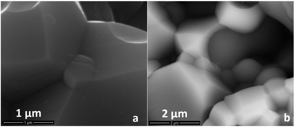 | ||
| Fig. 7 Secondary electron (a) and back-scattered electron micrographs (b) of the fracture cross-sections of BCZ20Y15–GDC15 50:50 dense membranes after permeation tests under C3 and C4 conditions up to 1040 °C and feeding 50% H2 in He. | ||
Stability against CO2
As reported by Haile et al., BaCe1−xZrxO3-based systems react with the carbon dioxide leading to the decomposition of the perovskite structure into barium carbonate and cerium oxide, according to the eqn (2):18 | (2) |
The incorporation of ceria, doped or un-doped, is expected to improve the thermodynamic stability of the composite material in CO2 or H2O atmospheres: indeed, the CeO2 phase shifts the equilibrium towards the reactant side, thus stabilizing the perovskite structure.29,35
In order to assess the potential use of these composite systems under operational conditions, their chemical stability was evaluated under CO2-rich atmospheres by means of thermogravimetric analyses. Fig. 8(a) shows TG curves recorded for BCZ20Y15–YDC15 and BCZ20Y15–GDC15 sintered powders (sintered at 1450 °C for 5 hours with ZnO) under N2 (100 mL min−1)/CO2 (20 mL min−1) continuous flow up to 1300 °C. For comparison, TG curves recorded for BaCe0.85Y0.15O3−δ (BCY15) and BaCe0.65Zr0.20Y0.15O3−δ (BCZ20Y15) powders exposed to the same treatment are shown in the graph as reference materials. Unlike BCY15 and BCZ20Y15 samples, very smaller weight uptakes (<0.2 wt%) were observed at T > 600 °C for BCZ20Y15–YDC15 and BCZ20Y15–GDC15 cer–cer membranes, thus indicating that the formation of barium carbonate was almost negligible (BaCO3 ≤ 1.8 mol%). It should be noted that these tests were performed on sintered powders in order to magnify the degradation effects of CO2 over the composites. In fact, no carbonation process could be ascribed from the TG curves registered under the same conditions for the cer–cer membranes in the form of sintered pellets.
 | ||
| Fig. 8 (a) TG curves of BCZ20Y15–YDC15 and BCZ20Y15–GDC15 50:50 and 60:40 composite powders registered under N2 (100 mL min−1)/CO2 (20 mL min−1) continuous flow. The TG data for BCY15 and BCZ20Y15 are reported for comparison. (b) H2 permeation measurements for the BCZ20Y15–GDC15 50:50 membrane at 750 °C for 24 h using 15% CO2 in Ar as sweep gas, 50% H2 in He as the feed gas under C3 conditions. | ||
These data are in agreement with XRD analyses of the sintered powders checked by TG: indeed, no phase changes are evident and only a few weak peaks ascribable to two BaCO3 phases (Rm space group no. 166 and Pmcn no. 62 respectively) are present in a practically negligible quantity (see also Fig. S8, ESI†).
H2 permeation measurements for a BCZ20Y15–GDC15 50:50 membrane were also performed at 750 °C for 24 h using 15% CO2 in Ar as sweep gas, 50% H2 in He as the feed gas, and C3 conditions. After a stabilization time under Ar, sweep gas was switched to 15% CO2 in an Ar atmosphere. H2 flux decreases quickly when CO2 is introduced and this drop can be related to the CO2/H2 competitive adsorption on the membrane surface.59 Then, the H2 flux increases for at least 24 hours as can be observed in Fig. 8(b). This increase can be related to a higher hydration of the membrane as it was previously reported for Nd5.5W0.5Re0.5O11.25−δ.59 H2 flux was recovered and surpassed when the sweep gas was switched to Ar, indicating the reversibility of the surface adsorption and the integrity of the membrane under CO2. These results attest a very good chemical stability of these cer–cer composite membranes against CO2 that is mandatory for their application under operational H2 separation conditions.
Conclusions
BCZ20Y15–YDC15 and BCZ20Y15–GDC15 cer–cer composite systems were investigated as H2 separation membranes at temperatures higher than 500 °C. In order to evaluate the influence of the protonic and electronic conductor phase on H2 permeation, symmetric dense BCZ20Y15–YDC15 and BCZ20Y15–GDC15 composite membranes both in 50:50 and 60:40 volume ratios were prepared. Chemical compatibility among precursors was confirmed by means of XRD analyses. Dense and crack free samples with homogeneous grain distribution and free-pore structures were obtained with reproducible densities by sintering treatments at 1450 °C with 1 wt% of ZnO as the sintering aid. This preparation procedure avoids high sintering temperatures, which are both expensive from the economic point of view and detrimental to the mechanical and electrical properties of composite membranes.
Permeation measurements were performed under different hydration degree conditions and H2 pressure gradients. BCZ20Y15–YDC15 50:50, BCZ20Y15–YDC15 60:40 and BCZ20Y15–GDC15 60:40 composite membranes exhibited very similar hydrogen fluxes under all studied conditions. BCZ20Y15–GDC15 50:50 membrane showed the highest H2 flux among all compositions studied reaching a value of 0.27 mL min−1 cm−2 at 755 °C when both sides of the membrane were hydrated. Moreover, by increasing the temperature, the flux noteworthily increased reaching at 1040 °C values up to 1.75 mL min−1 cm−2 and 2.40 mL min−1 cm−2 when both sides of the membrane (700 μm thick) or only the sweep side were hydrated respectively. These values are currently among the highest H2 fluxes recorded for bulk mixed protonic–electronic membranes. Moreover, these composite systems demonstrated a very good chemical stability under a CO2-rich atmosphere, as in real hydrogen separation processes.
Further investigations are underway in order to have a better understanding of the H2 permeation process in these materials, i.e. to determine the proton and oxygen ion transport contributions. Moreover, a thorough study on chemical and mechanical stability under a syngas atmosphere is necessary to validate the use of this kind of membrane under real operational conditions. The research aims to develop the optimal membrane materials and designs.
Acknowledgements
The authors are grateful to Dr Rosalba Gerbasi and Dr Filippo Agresti for their help in XRD analyses, to Dr Paolo Guerriero for his contribution in SEM investigations and to Dr Elisa Mercadelli for her expertise in sintered sample preparation. This work has been funded by the agreement between the Italian Ministry of Economic Development and the Italian National Research Council “Ricerca di sistema elettrico nazionale” and the Spanish Government (Grants ENE2014-57651, CSD-2009-0050 and SEV-2012-0267).Notes and references
- N. W. Ockwig and T. M. Nenoff, Chem. Rev., 2007, 107, 4078–4110 CrossRef CAS PubMed.
- J. W. Phair and S. PS. Badwal, Ionics, 2006, 12, 103–115 CrossRef CAS.
- L. Barelli, G. Bidini, F. Gallorini and S. Servili, Energy, 2008, 33, 554–570 CrossRef CAS PubMed.
- O. Bolland and H. Undrum, Adv. Environ. Res., 2003, 7, 901–911 CrossRef CAS.
- T. Norby and R. Haugsrud, in Nonporous inorganic membranes for chemical processing, ed. A. F. Sammels and M. V. Mundschau, Wiley-VCH, Verlag GmbH & Co. KGaA, 2006, ch. 1, pp. 1–48 Search PubMed.
- S.-J. Song, E. D. Wachsman, J. Rhodes, S. E. Dorris and U. Balachandran, Solid State Ionics, 2004, 167, 99–105 CrossRef CAS PubMed.
- S. Escolástico, C. Solís and J. M. Serra, Int. J. Hydrogen Energy, 2011, 36, 11946–11954 CrossRef PubMed.
- A. Magrasò and R. Haugsrud, J. Mater. Chem. A, 2014, 2, 12630–12641 Search PubMed.
- K. D. Kreuer, Annu. Rev. Mater. Res., 2003, 33, 333–359 CrossRef CAS.
- H. Iwahara, Y. Asakura, K. Katahira and M. Tanaka, Solid State Ionics, 2004, 168, 299–310 CrossRef CAS PubMed.
- G. Chiodelli, L. Malavasi, C. Tealdi, S. Barison, M. Battagliarin, L. Doubova, M. Fabrizio, C. Mortalò and R. Gerbasi, J. Alloys Compd., 2009, 470, 477–485 CrossRef CAS PubMed.
- S. M. Haile, G. Staneff and K. H. Ryu, J. Mater. Sci., 2001, 36, 1149–1160 CrossRef CAS.
- C. W. Tanner and A. V. Virkar, J. Electrochem. Soc., 1996, 143, 1386–1389 CrossRef CAS PubMed.
- E. Fabbri, A. D’Epifanio, E. Di Bartolomeo, S. Licoccia and E. Traversa, Solid State Ionics, 2008, 179, 558–564 CrossRef CAS PubMed.
- A. Magrez and T. Schober, Solid State Ionics, 2004, 175, 585–588 CrossRef CAS PubMed.
- S. Tao and J. T. S. Irvine, J. Solid State Chem., 2007, 180, 3493–3503 CrossRef CAS PubMed.
- S. Barison, M. Battagliarin, T. Cavallin, L. Doubova, M. Fabrizio, C. Mortalò, S. Boldrini, L. Malavasi and R. Gerbasi, J. Mater. Chem., 2008, 18, 5120–5128 RSC.
- K. H. Ryu and S. M. Haile, Solid State Ionics, 1999, 125, 355–367 CrossRef CAS.
- S. Barison, M. Battagliarin, T. Cavallin, S. Daolio, L. Doubova, M. Fabrizio, C. Mortalò, S. Boldrini and R. Gerbasi, Fuel Cells, 2008, 8, 360–368 CrossRef CAS PubMed.
- H. Kim, B. Kim, J. Lee, K. Ahn, H.-R. Kim, K. J. Yoon, B.-K. Kim, Y. W. Cho, H.-W. Lee and J.-H. Lee, Ceram. Int., 2014, 40, 4117–4126 CrossRef CAS PubMed.
- S. Fang, K. S. Brinkman and F. Chen, ACS Appl. Mater. Interfaces, 2014, 6, 725–730 CAS.
- S. Fang, K. S. Brinkman and F. Chen, J. Membr. Sci., 2014, 467, 85–92 CrossRef CAS PubMed.
- Z. Zhu, W. Sun, L. Yan, W. Liu and W. Liu, Int. J. Hydrogen Energy, 2011, 36, 6337–6342 CrossRef CAS PubMed.
- S. Fang, L. Bi, C. Yang, L. Yan, C. Chen and W. Liu, J. Alloys Compd., 2009, 475, 935–939 CrossRef CAS PubMed.
- C. Zuo, T. H. Lee, S. E. Dorris, U. Balachandran and M. Liu, J. Power Sources, 2006, 159, 1291–1295 CrossRef CAS PubMed.
- C. Zuo, S. E. Dorris, U. Balachandran and M. Liu, Chem. Mater., 2006, 18, 4647–4650 CrossRef CAS.
- S. Ricote, A. Manerbino, N. P. Sullivan and W. G. Coors, J. Mater. Sci., 2014, 49, 4332–4340 CrossRef CAS.
- J. S. Fish, S. Ricote, F. Lenrick, L. R. Wallenberg, T. C. Holgate, R. O’Hayre and N. Bonanos, J. Mater. Sci., 2013, 48, 6177–6185 CrossRef CAS.
- S. Elangovan, B. G. Nair, T. Small and B. Heck, US Pat., 8 012 380 B2, 2011 Search PubMed.
- S. Elangovan, B. G. Nair and S. Troy, EP Pat., 2 457 635 A1, 2012 Search PubMed.
- J. S. Fish, S. Ricote, R. O’Hayre and N. Bonanos, J. Mater. Chem. A, 2015, 3, 5392–5401 CAS.
- M. Mogensen, N. M. Sammes and G. A. Tompsett, Solid State Ionics, 2000, 129, 63–94 CrossRef CAS.
- Y. Xiong, K. Yamaji, T. Horita, N. Sakai and H. Yokokawa, J. Electrochem. Soc., 2002, 149, E450–E454 CrossRef CAS PubMed.
- J. B. Goodenough, Annu. Rev. Mater. Res., 2003, 33, 91–128 CrossRef CAS.
- D. Lin, Q. Wang, K. Peng and L. L. Shaw, J. Power Sources, 2012, 205, 100–107 CrossRef CAS PubMed.
- http://www.mariontechnologies.com/nanomateriaux/index.php .
- L. Lutterotti, S. Matthies, H.-R. Wenk, A. J. Schultz and J. Richardson, J. Appl. Phys., 1997, 81, 594–600 CrossRef CAS PubMed.
- T. Schober and H. G. Bohn, Solid State Ionics, 2000, 127, 351–360 CrossRef CAS.
- A. J. Bard and L. R. Faulkner, Electrochemical Methods, Wiley and Sons, New York, 2001, pp. 44–54 Search PubMed.
- S. Escolástico, M. Ivanova, C. Solís, S. Roitsch, W. A. Meulenberg and J. M. Serra, RSC Adv., 2012, 2, 4932–4943 RSC.
- P. Babilo and S. M. Haile, J. Am. Ceram. Soc., 2005, 88, 2362–2368 CrossRef CAS PubMed.
- S. Tao and J. T. S. Irvine, Adv. Mater., 2006, 18, 1581–1584 CrossRef CAS PubMed.
- L. Gao, M. Zhou, Y. Zheng, H. Gu, H. Chen and L. Guo, J. Power Sources, 2010, 195, 3130–3134 CrossRef CAS PubMed.
- H. wang, R. Peng, X. Wu, J. Hu and C. Xia, J. Am. Ceram. Soc., 2009, 92, 2623–2629 CrossRef CAS PubMed.
- D. Medvedev, A. Murashkina, E. Pikalova, A. Demin and A. Podias, Prog. Mater. Sci., 2014, 60, 72–129 CrossRef CAS PubMed.
- S. Escolastico, S. Somacescu and J. M. Serra, J. Mater. Chem. A, 2015, 3, 719 CAS.
- S. Ricote, N. Bonanos, M. C. Marco de Lucas and G. Caboche, J. Power Sources, 2009, 193, 189–193 CrossRef CAS PubMed.
- M. Cai, S. Liu, K. Efimov, J. Caro, A. Feldhoff and H. Wang, J. Membr. Sci., 2009, 343, 90–96 CrossRef CAS PubMed.
- H. Matsumoto, T. Shimura, H. Iwahara, T. Higuchi, K. Yashiro, A. Kaimai, T. Kawada and J. Mizusaki, J. Alloys Compd., 2006, 408–412, 456–462 CrossRef CAS PubMed.
- S. Escolastico, C. Solis, C. Kjolseth and J. M. Serra, Energy Environ. Sci., 2014, 7, 3736–3746 CAS.
- M. Ruf, C. Solís, S. Escolástico, R. Dittmeyer and J. M. Serra, J. Mater. Chem. A, 2014, 2, 18539–18546 CAS.
- S. Escolastico, M. Schroeder and J. M. Serra, J. Mater. Chem. A, 2014, 2, 6616–6630 CAS.
- S. Escolástico, S. Somacescu and J. M. Serra, Chem. Mater., 2014, 26, 982–992 CrossRef.
- S. Escolástico, C. Solís, T. Scherb, G. Schumacher and J. M. Serra, J. Membr. Sci., 2013, 444, 276–284 CrossRef PubMed.
- S. Wang, H. Inaba, H. Tagawa, M. Dokiya and T. Hashimoto, Solid State Ionics, 1998, 107, 73–79 CrossRef CAS.
- J. Kniep and Y. S. Lin, Ind. Eng. Chem. Res., 2010, 49, 2768–2774 CrossRef CAS.
- Y. Wei, J. Xue, W. Fang, Y. Chen, H. Wang and J. Caro, Chem. Commun., 2015, 51, 11619–11621 RSC.
- S. M. Haile, G. Staneff and K. H. Ryu, J. Mater. Sci., 2001, 36, 1149–1160 CrossRef CAS.
- K. Sato, M. Nishioka, H. Higashi, T. Inoue, Y. Hasegawa, Y. Wakui, T. M. Suzuki and S. Hamakawa, J. Membr. Sci., 2012, 415–416, 85–92 CrossRef CAS PubMed.
Footnote |
| † Electronic supplementary information (ESI) available: Densities, and XRD, SEM and OCV data of precursors and composite membranes. Additional H2 flux tests, and SEM and XRD data after H2 permeation and TGA tests. See DOI: 10.1039/c5ee01793a |
| This journal is © The Royal Society of Chemistry 2015 |