 Open Access Article
Creative Commons Attribution 3.0 Unported Licence
Energy decomposition analysis approaches and their evaluation on prototypical protein–drug interaction patterns†
Maximillian J. S.
Phipps
a,
Thomas
Fox
b,
Christofer S.
Tautermann
b and
Chris-Kriton
Skylaris
*a
aSchool of Chemistry, University of Southampton, Highfield, Southampton, SO17 1BJ, UK. E-mail: C.Skylaris@soton.ac.uk
bLead Identification and Optimization Support, Boehringer Ingelheim Pharma GmbH & Co. KG, 88397 Biberach, Germany
First published on 2nd April 2015
Abstract
The partitioning of the energy in ab initio quantum mechanical calculations into its chemical origins (e.g., electrostatics, exchange–repulsion, polarization, and charge transfer) is a relatively recent development; such concepts of isolating chemically meaningful energy components from the interaction energy have been demonstrated by variational and perturbation based energy decomposition analysis approaches. The variational methods are typically derived from the early energy decomposition analysis of Morokuma [Morokuma, J. Chem. Phys., 1971, 55, 1236], and the perturbation approaches from the popular symmetry-adapted perturbation theory scheme [Jeziorski et al., Methods and Techniques in Computational Chemistry: METECC-94, 1993, ch. 13, p. 79]. Since these early works, many developments have taken place aiming to overcome limitations of the original schemes and provide more chemical significance to the energy components, which are not uniquely defined. In this review, after a brief overview of the origins of these methods we examine the theory behind the currently popular variational and perturbation based methods from the point of view of biochemical applications. We also compare and discuss the chemical relevance of energy components produced by these methods on six test sets that comprise model systems that display interactions typical of biomolecules (such as hydrogen bonding and π–π stacking interactions) including various treatments of the dispersion energy.
1 Introduction
Intermolecular interactions govern the formation of many systems of interest, and their study is therefore of particular importance within many fields such as materials and medicinal chemistry, catalysis and biochemistry. Physical experimentation alone is unable to provide readily identifiable values for the chemical phenomena that give rise to the interactions, and no quantum mechanical (QM) operators exist that we may use to compute interaction energies or chemical/physical components of these. However, the development of energy decomposition analysis (EDA) presents a novel approach to quantifying these chemical effects. EDA is a valuable analytical tool that partitions the intermolecular interaction energy into energy components such as electrostatic, polarization, charge transfer, exchange and correlation contributions and related chemical phenomena. A significant number of recent developments have been made in the field of EDA, and with such diversity it is not unexpected that certain schemes should possess a greater suitability for application to one field of chemistry above another (e.g. application to transition metal systems or hydrogen bonded model systems). It is for this reason that we have decided to limit our review of EDA schemes in this work specifically to those of interest in biomolecular applications.There exist many possible ways in which to decompose the interaction energy. The different approaches are the result of the essentially arbitrary definitions of the interaction energy components that originate from the desired chemical concepts. It is important to note a number of problems that relate to this arbitrary nature. For example, at close intermolecular distances and especially with large basis sets the separation of charge transfer and polarization becomes increasingly ill-defined. At greater intermolecular distances charge transfer becomes more easily separable from polarization, eventually reaching the limit of transferring integer charges between molecules. From the more distant perspective of considering the theoretical grounding from which the energy components are obtained, it may also be argued that there are only classical electrostatic interactions that can be decomposed.
In order to compare the effectiveness of particular EDA schemes it is important to highlight their key distinguishing features and compare these with others. Measures of EDA scheme effectiveness include the physical relevance of the energy component magnitudes and the agreement of energy term characteristics through a series of changing chemical environments. Also, the ability to express correlation effects such as dispersion may also be beneficial for example in the case of weakly interacting systems. Often consideration of the computational expense of executing a decomposition, particularly in the case of biological systems analyses which are typically of larger size, is also important. Special features of schemes may also prove to be of merit for certain applications. Such features include the ability to further decompose terms into their monomeric contributions, as well as the measurement of forward and back-donation of electron density between molecules. Corrections for basis set superposition error are also included in many EDA schemes, and the theory of these will also be discussed within this work.
One picture we may use to determine the expressive power of the terms is through consideration of the exploratory depth of the decomposition at hand. For example, the absolutely localized molecular orbital1 (ALMO) and similar block-localized wavefunction2 (BLW) EDA schemes define a frozen density term at the Hartree–Fock (HF) level of theory. This term can be represented as the addition of the electrostatic and exchange interaction terms. On the other hand, a separation of terms is seen within the earlier implementation of the natural EDA (NEDA) approach of Glendening et al.3–6 The original ‘electrostatic’ component of the scheme3 incorporated the polarization and exchange contributions to the interaction energy in addition to the more commonly understood electrostatic component. An early extension of the scheme4 separates these terms into their isolated components. The compounding and separation of terms may in cases hinder the depth of analysis available to the chemist. Equally, however, such groupings may be of benefit for other applications. In reviewing the various EDA schemes, it is also important to be aware of complications that arise due to term inequivalencies between the schemes despite sharing term names. Similarly, it is important to also note term dependencies within schemes that may be present. This includes consideration, for example, of issues surrounding the so-called ‘mixing’ term of the Kitaura–Morokuma (KM) EDA scheme.7 This is a residual energy term that describes a contribution to the interaction energy that is unascribable to any particular chemical energy component.
The application of a scheme to a particular system may be limited by the level of theory at which a scheme is implemented. Schemes implemented at the higher levels of theory often include dispersion and other correlation components not available at the HF level of theory. For example, we may consider the case of the localized molecular orbital (LMO) EDA scheme of Su and Li8 that is implemented for restricted closed shell HF (RHF), restricted open shell HF (ROHF), and unrestricted open shell HF (UHF) monomer wavefunctions and the density functional theory (DFT) equivalents of these. Treatment of intramolecular bond splitting interactions is possible within this scheme in addition to intermolecular interactions. A number of the schemes have been re-expressed at the coupled cluster (CC) level of theory, offering the possibility of highly accurate theoretical study of systems.8–10
This review is structured as follows: firstly we introduce the various self-consistent field (SCF) theories and charge-localized molecular orbital (MO) descriptions used within the EDA formalisms, and also describe a common wavefunction form used for the expression of the various EDA methods' theoretical descriptions. Following this, we discuss a number of common EDA schemes of potential interest for biomolecular system investigations, and finally evaluate these schemes using a study of a test set of small model systems that express key interactions commonly found within biomolecular systems.
2 Previous applications of energy decomposition analysis
EDA has been used in a wide range of applications in quantum chemistry. Investigations using EDA approaches are naturally well suited to evaluations of molecular bonding forces. The EDA studies in literature typically feature systems of relatively small size (up to tens of atoms) for both the variational1–6,8,11–17 and perturbation approaches,18–21 and for biomolecular systems approaches such as molecular mechanics (MM) are sometimes combined with the QM region.22,23 Here we discuss a number of these applications in literature.EDA calculations in the literature have typically been performed to evaluate newly developed EDA methodologies, to quantify the driving forces of association in the studied systems, or for both reasons. The water dimer has been frequently adopted as a theoretical test model for the purpose of evaluating new EDA approaches1,3,5,6,11–13,24 as this system is exemplary of a typical hydrogen bonding interaction. Other small interacting systems also studied include the benzene dimer system,8,17,21 the water–alkali metal cation series1,4,5,11 and the ammonia–hydrogen fluoride12,15,18 system.
EDA calculations of drug–water clusters have also been performed. For example, investigations were performed by Esrafili and Behzadi25 on the hydrogen bonding interaction of aspirin (and fluorine-substituted aspirin) with (water)n=1–3. This work included symmetry-adapted perturbation theory (SAPT) and natural bond orbital (NBO) second-order perturbation theory analyses, as well as density partitioning using Bader's quantum theory of atoms in molecules (QTAIM)26 approach.
Investigations of larger biomolecules are also noted in the EDA literature. These are typically performed by EDA calculations on smaller derived truncated systems, rather than on the whole biomolecular system itself. Truncated active-site systems of a Cl−/H+ exchange transporter protein (EcClC) were studied with KM EDA and NEDA by Church et al.27 for example. A number of EDA investigations of cytochrome P450 have also been performed.22,23,28 Thellamurege investigated the interaction of a water molecule with cytochrome P450, specifically with the ferric heme group and compound I intermediate of this biomolecule.28 This investigation was performed using the LMO EDA8 and the extended transition state (ETS) EDA developed by Ziegler and Rauk.29–31 The results revealed electrostatic and polarization effects to be dominant in the interactions within these systems.
The possibility of EDA on larger systems also has been evidenced. Hirao performed an EDA of the ONIOM(B3LYP:AMBER) QM/MM interaction energy of the compound I intermediate of cytochrome P450cam to investigate the effect of the protein environment on this state.23 This work found electrostatics to be the most dominant contribution to the interaction energy, followed by van der Waals and polarization contributions. The calculations of this investigation involved thousands of atoms present in the protein environment, and even though this involved a QM/MM-based variant of EDA, this study offers an example of EDA application to an entire protein. An earlier investigation by Hirao using this method was also performed on the non-heme diiron enzyme myo-inositol oxygenase.22 The aim of this investigation was to assess the effects of the protein environment and intracluster dispersion in the process of oxygen binding to this enzyme. This found dispersion to be the most dominant contribution to the interaction energy, which was enhanced to a lesser degree by electrostatic, van der Waals, and polarization effects. This work notes that because entropic effects do not favour the bonding of oxygen, overall this process is almost thermoneutral. This demonstrates a limitation of pure interaction energy investigations: the interaction energy (or enthalpy) itself is also one of the components that control the thermodynamics of binding, the other being the entropy of binding.
Another established approach to large scale energy calculations is the fragment molecular orbital (FMO) framework of Kitaura et al.32–35 This approach involves the partitioning of a system into a number of smaller fragments, with the total system energy calculated using the FMOs of these fragments. This fragmentation reduces computational cost whilst maintaining accuracy, and a number of studies have been performed on important protein–receptor systems using the FMO approach investigating binding affinities and the interaction energies of fragments. Examples of these studies include calculations performed on the human immunodeficiency virus type 1 (HIV-1) protease complexed with lopinavir,36,37 the HIV-1 antibody 2G12,38,39 the influenza virus surface protein hemagglutinin,40–50 prion protein,51–53 the estrogen receptor,54–56 the vitamin D receptor,57–60 and the retinoid X receptor.61–63 The pair interaction EDA (PIEDA) scheme24 has been developed in the FMO framework, and a discussion of the PIEDA approach is included later in this review. The PIEDA scheme has been used to investigate contributions to stabilization in various conformers in the evolution of amide stacking in larger γ-peptides,64 and to investigate DNA recognition modulation in artificial zinc-finger proteins using PIEDA maps.65
Investigations are not limited to low atomic mass compositions. EDA calculations of the bonding in more exotic systems have been published, such as in the transition metal–oxime bond66 and the transition metal–imine bond67 by Bayat et al., and work by Marjolin et al.68 has sought to seek the components of interactions within mono aqua complexes of various lanthanide and actinide cations. This work investigating lanthanide and actinide cation interactions was achieved using a modified constrained space orbital variation (CSOV) EDA scheme69,70 with small and large core pseudopotentials.
Overall, the current work shows EDA to be a rapidly expanding field of quantum chemistry. Calculations on ever larger systems have been made possible, and many different EDA approaches now exist. So far no systematic approach has been made to evaluating these many approaches. It is the aim of this review to summarize the current methods with focus on their application to biomolecular structures. It is also often the case that the EDA approaches under study are applied to distinctly different chemical compositions in literature. We have therefore decided to evaluate the methods using test sets each containing a series of compounds (e.g. of increasing hydrogen bonding interaction character) to facilitate the translation of chemical expectations into the various energy contributions.
3 Theory of self-consistent field calculations
We now describe the term symbols used in this review.Energies
| E HF | Hartree–Fock energy |
| E KS | Kohn–Sham energy |
| T | Electronic kinetic energy |
| T s | Non-interacting electronic kinetic energy |
| V ee | Electron–electron interaction energy |
| J | Coulombic interaction energy |
| E xc | Exchange and correlation energy |
| ε i | Molecular orbital energy |
| ΔE | Interaction energy |
Operators
![[F with combining circumflex]](https://www.rsc.org/images/entities/i_char_0046_0302.gif)
| Fock operator |
![[K with combining circumflex]](https://www.rsc.org/images/entities/i_char_004b_0302.gif)
| Exchange operator |
| Â | Antisymmetrizer operator |
Potentials
| υ eff(r) | Effective potential |
| υ ext(r) | External potential |
| υ xc(r) | Exchange–correlation potential |
System parameters and constants
| N frag | Number of fragments in the fragment molecular orbital system |
| N s | Number of doubly-occupied spatial orbitals |
| r,r′ | Electronic coordinate |
| R α | Coordinate of nucleus α |
| Z α | Charge of nucleus α |
Ab initio theory
| f[n] | Functional |
| n(r) | Density |
| Ψ(r,R),|Ψ〉 | Total electron-nuclear wavefunction |
| ψ i (r),|ψi〉 | Molecular orbital |
| ϕ i (r),|ϕi〉 | Basis function/atomic orbital |
Matrices and integrals
| F | Fock matrix |
| C | Orbital coefficient matrix |
| D x | Fragment molecular orbital density matrix for fragment(s) x |
| V x | Electrostatic potential of the other fragments acting upon the fragment(s) x |
| K ij | Exchange integral |
| 〈μγ|νδ〉 | Two-electron integral |
Natural bond orbitals
| o ϕ i (r),|oϕi〉 | Natural atomic orbital |
| w i | Orbital occupancy |
| o a i | Natural atomic orbital expansion coefficient |
| a X | Polarization coefficient of natural hybrid orbital hX |
| φ X(r),|φX〉 | Natural bond orbital |
Fragment molecular orbitals
| E FMO2 | Fragment molecular orbital system energy |
| E I | Energy of fragment I |
| E I ′ | Internal energy of fragment I |
| ΔEintIJ | Pair interaction energy of fragments I and J |
Symmetry-adapted perturbation theory
| Ŵ | Møller–Plesset fluctuation operator |
| ξ,η,ζ | Perturbation parameters |
![[V with combining circumflex]](https://www.rsc.org/images/entities/i_char_0056_0302.gif)
| Intermolecular Coulomb operator |
![[v with combining circumflex]](https://www.rsc.org/images/entities/i_char_0076_0302.gif) A(b)
A(b) | Coulombic potential of the nuclei of fragment A on electron b |
| V 0 | Nuclear interaction energy between the fragments of a system |
3.1 Density functional theory
In Kohn–Sham (KS)73 DFT,74 the total electronic energy is calculated using the KS energy functional, | (1) |
 | (2) |
| ĥKSψi(r) = εiψi(r) | (3) |
 | (4) |
The KS effective potential has the form,
 | (5) |
 | (6) |
On calculating υeff(r) from a guessed density n(r) using eqn (5), a new density is found using eqn (2) and (3). These equations are solved in a self-consistent manner until energy convergence is achieved.
3.2 Hartree–Fock theory
The HF75,76 approach unlike DFT is not formally an exact theory but can be considered as a special case of the KS equations with ĥKS of eqn (3) replaced with the Fock operator![[F with combining circumflex]](https://www.rsc.org/images/entities/i_char_0046_0302.gif) ,
,![[F with combining circumflex]](https://www.rsc.org/images/entities/i_char_0046_0302.gif) ψi(r) = εiψi(r) ψi(r) = εiψi(r) | (7) |
 | (8) |
 | (9) |
The HF equations are also solved in a self-consistent manner. A set of guess orbitals are used to construct the Fock operator using eqn (8) which is then solved to find the orbitals that minimize the HF energy,
 | (10) |
 | (11) |
3.3 The localized molecular orbital description
Within the variational EDA approaches, the interaction energy is partitioned by constructing a number of intermediate wavefunctions that express chemical phenomena between the monomer units and calculating the energy difference between these wavefunctions. For example, in the case of the polarization contribution this would be calculated as the energy difference between the non-polarized state and polarized state, where the description of the polarized state necessarily excludes any charge transfer interaction. There is a multitude of approaches which have been followed for the needed wavefunction restriction in order to construct these polarized but charge transfer restricted intermediate wavefunctions and so these approaches are a defining feature of each EDA. Similarly, unique basis set frameworks in which the EDAs are performed are required specifically for the NEDA3–6 (NBO71,72 framework) and PIEDA24 (FMO32–35 framework) approaches. The key theoretical frameworks employing localized MOs and polarized wavefunction constructions are briefly summarized here.For the subset of AOs localized to each fragment, where x denotes a subset belonging to a fragment and μ denotes the basis function index within a given subset, the occupied MOs of each fragment are expanded in terms of their respective localized AOs,
| |ψxi〉 = |ϕxμ〉Cxμ··xi | (12) |
The theory underlying the construction of ALMOs is closely related to that of the block-localized MOs of Mo et al.2,11 (the BLW method). The ALMO and BLW wavefunctions may be considered almost identical in their construction, differing by the method of orbital optimization within the theories. The procedure by which the ALMOs are variationally optimized is known as SCF for molecular interactions (SCF MI).77–79 Orbital optimization within the BLW approach may follow a similar procedure,78,80–82 or may be achieved by successive Jacobi rotation.83 Despite the similarities that exist in the construction of these wavefunctions, a number of small differences are observed in the EDA schemes they are used within as we discuss in the sections dedicated to each method.
Construction of the NBO basis involves the progressive transformation of the atomic orbital basis into localized functions. This begins with the initial transformation of the atomic orbital basis set into natural atomic orbitals (NAOs) of optimized occupancy by occupancy-weighted symmetric orthogonalization (OWSO).72,84,85 For a set of atomic orbitals {|ϕi〉}, a set of NAOs {|oϕi〉} is constructed as,
| {|oϕi〉} = {|ϕi〉}COWSO | (13) |
 | (14) |
This set of high-occupancy core and valence orbitals and low-occupancy Rydberg orbitals are then linearly combined to form an optimal orthonormal set of natural hybrid orbitals (NHOs) {hX} which are directional and point along chemical bonds,
 | (15) |
Linear combination of the NHOs results in construction of a set of 2-centre bonding NBOs,
| φXY(r) = aXhX(r) + aYhY(r) | (16) |
| φXY*(r) = aXhX(r) − aYhY(r). | (17) |
In the FMO approach, selected chemical bonds are detached at an atom with the two bonding electrons assigned to one of the fragments. Ideally, this detachment should avoid regions of delocalized charge such as C–N amide bonds in order to maintain the localized nature of the fragments. The atom retaining this bond is named the bond attached atom (BAA), and the atom from which this bond is detached is named the bond detached atom (BDA).86 Essentially, the HOP technique is used in order to prevent the BDA electron density from occupying the region of the bond that is now occupied by the BAA.
On the BAA fragment, a pseudoatom replaces the BDA to provide the basis functions used to describe the bond and a proton from the BDA is formally transferred to this pseudoatom. This transfer does not affect the electrostatic field surrounding the fragment, and so the total properties of the system remain unaltered.
A brief description of the general FMO formalism and FMO system energy calculation is as follows:87
(1) The system is partitioned as determined by the user into a number of fragments with BDAs and BAAs.
(2) Initial monomer electron densities are constructed for optimization.
(3) Monomer Fock operators are subsequently constructed using these densities, and the monomer energies evaluated in the electrostatic field of the surrounding fragments.
(4) These energies are self-consistently minimized to a converged electrostatic potential.
(5) Two-fragment energy calculations (FMO2) are performed in this potential and used to evaluate the total energy of the system. These dimer energies are calculated using the converged fragment densities.
(6) Three-fragment calculations (FMO3) may also be performed and used to calculate the total system energy including three-body effects. Similarly, these trimer energies are calculated using the converged fragment densities.
The FMO2 total system energy is expressed as a many-body expansion up to second-order as,
 | (18) |
 | (19) |
| ΔDIJ = DIJ − DI ⊕ DJ | (20) |
| EIJ′ = EIJ − Tr(DIJVIJ) | (21) |
The FMO2 energy form of eqn (19) can be re-expressed in terms of internal monomer energies and PIEs, ΔEintIJ, as,
 | (22) |
| ΔEintIJ = (EIJ′ − EI′ − EJ′) + Tr(ΔDIJVIJ) | (23) |
3.4 Common EDA wave functions
It is useful to adopt a unified notation of the wavefunctions (and their derived charge densities) shared between the EDA schemes we consider in this review. Starting with the direct calculation of the interaction energy, we define the commonly used electronic Slater determinant wavefunctions Ψ0,ABA, Ψ0,ABB and ΨAB and other related intermediate wavefunctions used to express the EDA theory. We denote the lower index as distinguishing the fragment(s) described by the wavefunction, and the upper index as distinguishing the basis in which the MOs of the wavefunction are expanded. The upper index zero describes wavefunctions constructed using the optimized MOs of fragments in isolation. The Boys and Bernardi89 counterpoise (CP) corrected binding energy calculation may be expressed as,| ΔE = E[ΨAB] − E[Ψ0,ABA] − E[Ψ0,ABB] | (24) |
 ,
,  and
and  ,
,  may be derived to facilitate the partitioning of the CP correction into a contribution from ghost occupied orbitals of the adjacent fragments and from ghost virtual orbitals of the adjacent fragments. These wavefunctions are constructed in the same manner as Ψ0,ABA, and Ψ0,ABB, but using either the occupied or virtual orbitals of the adjacent fragments as given by the upper index. We define the wavefunctions for the monomers calculated in their own basis as,
 | (25a) |
 | (25b) |
A number of many-electron intermediate wavefunctions are defined for the complex AB using combinations of the MOs of the monomers A and B. The first set of wavefunctions of this type, Ψ0,A/B,HartreeAB and Ψ0,AB,HartreeAB, are constructed as the Hartree product of the individual monomer Slater determinant wavefunctions. This means that interfragmental exchange is not included in the energies of these two wavefunctions. As before, a key feature of these wavefunctions is the basis in which the individual monomer MOs are optimized. The wavefunction Ψ0,A/B,HartreeAB is constructed using the MOs of the individual monomers A and B optimized in isolation in their own basis, and the wavefunction Ψ0,AB,HartreeAB is constructed using the monomer MOs optimized in isolation in the full AB basis:
| Ψ0,A/B,HartreeAB = [Ψ0,AA·Ψ0,BB] | (26a) |
| Ψ0,AB,HartreeAB = [Ψ0,ABA·Ψ0,ABB]. | (26b) |
The second set of wavefunctions of this type are Ψ0,A/BAB and Ψ0,ABAB which are constructed in the same manner as Ψ0,A/B,HartreeAB and Ψ0,AB,HartreeAB but taking the antisymmetric product of the monomer MOs as,
| Ψ0,A/BAB = Â(Ψ0,AA·Ψ0,BB) | (27a) |
| Ψ0,ABAB = Â(Ψ0,ABA·Ψ0,ABB). | (27b) |
3.5 Common EDA charge densities
In this section we describe the charge densities corresponding to the intermediate wavefunctions above which are used to provide a description of the NEDA scheme theory.3–6 Similar to the wavefunction indices' definitions, we use the lower index to denote the fragment(s) described by the charge density and the upper index to denote the basis in which the density is constructed. The construction of charge densities within the NEDA scheme proceeds by decomposition of the charge density of the AB supermolecule rather than by construction from the monomer charge densities, and all charge densities of this scheme are calculated in the full AB basis. We also distinguish densities optimized in isolation by an upper index zero.The charge densities nABAB, n0,ABA and n0,ABB describe the charge densities of the fully optimized AB supermolecule and the isolated monomers A and B respectively. The descriptions of these charge densities complement the commonly used wavefunctions ΨAB, Ψ0,ABA and Ψ0,ABB respectively. The charge density of the AB supermolecule, nABAB, is given by,
 | (28) |
 | (29a) |
 | (29b) |
4 Variational based EDA methods
4.1 Kitaura–Morokuma EDA
The KM scheme,7,90 extended from the scheme of Morokuma,91 is one of the earliest energy decomposition analysis schemes developed. This scheme is a widely used variational scheme limited to the RHF level of theory and which therefore excludes electronic correlation terms within the decomposition.| ΔE = ΔEES + ΔEEX + ΔEPOL + ΔECT + ΔEMIX | (30) |
We express the components of the KM EDA scheme except the charge transfer component in terms of energy functionals of the common wavefunctions described above. The electrostatic energy, ΔEES, is evaluated as the Coulomb energy on taking the relaxed charge densities of the monomers in isolation to complex geometry,
| ΔEES = E[Ψ0,A/B,HartreeAB] − E[Ψ0,AA] − E[Ψ0,BB]. | (31) |
| ΔEEX = E[Ψ0,A/BAB] − E[Ψ0,A/B,HartreeAB]. | (32) |
| ΔEPOL = E[ΨA/B,HartreeAB] − E[Ψ0,A/B,HartreeAB] | (33) |
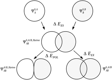 | ||
| Fig. 1 The Kitaura–Morokuma electrostatics, exchange and polarization EDA components for the AB complex.7,90 | ||
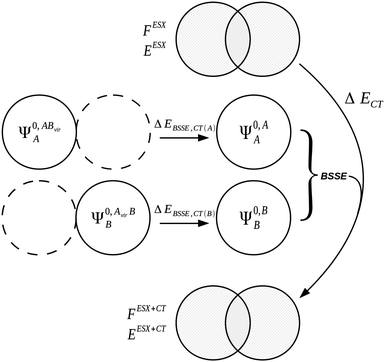
The charge transfer component is calculated as the energy resulting from charge transfer from the occupied MOs of one monomer to the virtual MOs of the other and vice versa. The calculation of this component may be described as the energy difference between two intermediate wavefunctions: one that includes this interfragmental interaction, and one that does not. The calculation of this energy component is more clearly demonstrated by use of modified overlap and Fock matrices for the AB complex. The charge transfer energy component of this scheme is calculated by setting to zero certain blocks of the complex Fock and overlap matrices that express specific chemical effects during the iteration cycles. The matrices of the complex are partitioned into blocks that involve the occupied and virtual orbitals of each monomer. The contribution of charge transfer effects to the interaction energy may be calculated as the difference between the energy of an intermediate set of matrices that have non-zero diagonal blocks which we name ‘ESX’ blocks that give an energy EESX, and another set of intermediate matrices that involve both the diagonal ‘ESX’ blocks and those blocks required to describe charge transfer effects which we name ‘CT’ blocks with energy EESX+CT. These matrices are shown diagrammatically within Fig. 2.
| ΔECT = EESX+CT − EESX. | (34) |
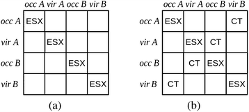 | ||
| Fig. 2 The partitioning of the Fock and overlap matrices for the KM EDA scheme for the evaluation of the charge transfer component.7,13 The set of matrices (a) that involve only the diagonal exchange and electrostatics interactions produces the energy EESX and the set of matrices (b) that involve these diagonal blocks and also the charge transfer blocks produces the energy EESX+CT. The labels ‘occ’ and ‘vir’ denote the sets of orbitals that are occupied and virtual on the monomers A and B. | ||
A remainder ‘mixing’ term is defined to describe the contribution to the interaction energy not ascribable to any particular component of the scheme,
| ΔEMIX = ΔE − (ΔEES + ΔEPOL +ΔECT + ΔEEX). | (35) |
The KM theory described herein follows the implementation of Chen and Gordon.13 Treatment of BSSE in this scheme applies the CP correction to the ΔEEX and ΔECT terms only and the components ΔEES, ΔEPOL and ΔEMIX remain as in the original KM EDA scheme. This treatment splits the CP correction to the interaction energy into two: one correction for the exchange component calculated by including the set of occupied orbitals of the adjacent fragments, and a second correction for the charge transfer component calculated by including the set of virtual orbitals of the adjacent fragments. The CP corrections to the ΔEEX term are given as,
 | (36a) |
 | (36b) |
| ΔEBSSE,EX = ΔEBSSE(A) + ΔEBSSE(B) | (36c) |
 | (37a) |
 | (37b) |
| ΔEBSSE,CT = ΔEBSSE(A) + ΔEBSSE(B). | (37c) |
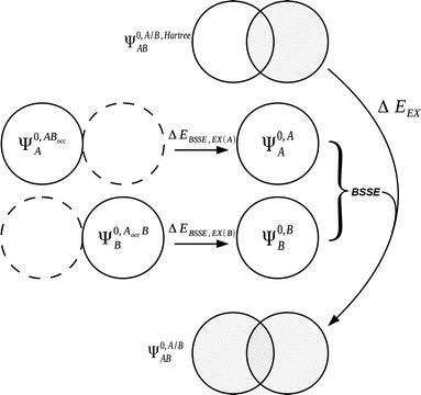 | ||
| Fig. 3 The treatment of BSSE13 for the exchange term within the KM EDA scheme.7,90 A BSSE correction due to the presence of the occupied orbitals of adjacent monomers is introduced to the exchange term. | ||
| ΔE = ΔEES + ΔEPauli + ΔEorb. | (38) |
| ΔEPauli = Exc[Ψ0,A/B,HartreeAB] − (Exc[Ψ0,AA] + Exc[Ψ0,BB]). | (39) |
As seen within other schemes, the description of ΔEES and ΔEEX as individual terms remains problematic due to their wavefunction definitions not obeying the Pauli principle. These terms are often combined in schemes derived from the KM EDA to produce a new term that is defined by the addition of the electrostatic and exchange terms. This combined term avoids the problem of using improperly antisymmetrized wavefunctions in the decomposition. The ΔECT and ΔEPOL KM EDA components are also observed to share the problem of using improperly antisymmetrized wavefunctions in their calculation. These terms may be combined as a new ΔECTPLX term which is defined by the addition of the polarization and charge transfer components with inclusion of the exchange integral: this is performed in an alternative scheme100 intended for the analysis of strong transition metal–ligand interactions.
The ETS scheme has been coupled in recent years with the natural orbitals for chemical valence (NOCV) approach101–104 in what is termed ETS-NOCV.93 This method allows the orbital interaction energy ΔEorb to be divided into its orbital origins and visualised. In this approach, a deformation density matrix describing the change in density of the ΔEorb interaction is constructed and diagonalised to yield NOCVs.93 Complementary pairs of NOCVs are used to visualise the interactions, with energetic estimations of these interactions computed from the KS matrix of a transition state density (midway between the supermolecule and fragment densities). This approach therefore provides both a qualitative and quantitative analysis of chemical bonding. The ETS-NOCV scheme has been applied to organometallic105–108 and coordination compounds,105,107–109 as well as metal–metal bonding93,108 and boronic110,111 systems. More unusual organometallic analyses have also been performed using the ETS-NOCV approach, including systems involving gold112 and silver113 interactions for example. The ETS EDA scheme has also been applied to purely organic molecules, for example in investigating conjugation and hyperconjugation stabilizations in conjugated molecules,114 benzene,116 five-membered aromatic compounds,116 cyclic and acyclic conjugated carbenes,116 and hetero-115,116 and anti-aromatic compounds.116 Additionally, a number of review articles have been published on applications of the ETS scheme to both inorganic117,118 and organic systems.14,119 Other approaches that seek to provide a measure of the electron density delocalization between molecules include the NBO approach,71,72,84,120,121 Bader's QTAIM,26,122 the electron localization function,123,124 and the Hirshfeld analysis,125 as well as the various population analysis schemes.72,92,126
4.2 Reduced variational space
The RVS scheme13,99 corrects a number of the unsatisfactory tendencies of the KM scheme that result as a consequence of the terms not correctly satisfying the Pauli exclusion principle in their calculation.98 The CSOV analysis69,70 is similar to the RVS scheme and differs subtly in its treatment of charge transfer and polarization. By ensuring proper antisymmetrization of the wavefunctions of the decomposition, the Pauli exclusion principle within the RVS scheme is enforced correctly. Effectively, this scheme combines the electrostatics and exchange terms of the KM EDA and modifies the evaluations of the polarization and charge transfer components.The form of the RVS EDA interaction energy partitioning is,
| ΔE = ΔEESX + ΔEPOL + ΔECT + ΔEMIX | (40) |
| ΔEESX = E[Ψ0,A/BAB] − E[Ψ0,AA] − E[Ψ0,BB] | (41) |
The remaining components are modifications to their KM EDA equivalents. The polarization energy component differs from the KM EDA evaluation by variational optimization of the fully antisymmetrized wavefunction Ψ0,A/BAB (rather than the non-antisymmetrized wavefunction Ψ0,A/B,HartreeAB). The subspace available for variational optimization of the orbitals is reduced by freezing (and Gram-Schmidt orthogonalizing) the occupied orbitals of the neighbouring monomer and omitting its virtual orbital subspace to prevent charge transfer. For the two-fragment system AB, orbital optimization in the field of the neighbouring monomer produces two wavefunctions ΨRVS-POL(A),A/BAB and ΨRVS-POL(B),A/BAB relating to the polarized states of fragments A and B respectively. The polarization energies for these two wavefunctions are then calculated by subtraction of the energy of the non-polarized state wavefunction Ψ0,A/BAB from the energies of these polarized state wavefunctions. Addition of these two polarization energies produces the total polarization energy EPOL.
| ΔEPOL(A) = E[ΨRVS-POL(A),A/BAB] − E[Ψ0,A/BAB] | (42a) |
| ΔEPOL(B) = E[ΨRVS-POL(B),A/BAB] − E[Ψ0,A/BAB] | (42b) |
| ΔEPOL = ΔEPOL(A) + ΔEPOL(B) | (42c) |
Repeating a similar process of orbital optimization but with extension of the variational space to include the virtual orbitals of the neighbouring fragment allows charge transfer to occur, producing the two wavefunctions ΨRVS-CT(A),A/BAB and ΨRVS-CT(B),A/BAB relating to the polarized and charge transferred states of fragments A and B respectively. The difference between the energies of these wavefunctions and their polarized-only counterparts, ΨRVS-POL(A),A/BAB and ΨRVS-POL(B),A/BAB, provides the charge transfer energies of fragments A and B. The BSSE contributions from each fragment for charge transfer are introduced at this point in the decomposition. We denote the CP corrected charge transfer energies EBSSE,CT(A) and EBSSE,CT(B) for the CP correction to charge transfer originating from monomers A and B respectively, and the total of these two energies as ΔEBSSE,CT. The BSSE contributions from each fragment are introduced in a form similar to eqn (37a) and (37b). This CP correction is referred to as the CP correction with virtual orbitals (VCP) in literature.13 Addition of the BSSE contributions from the fragments produces the total charge transfer energy ECT+BSSE.
| ΔECT+BSSE(A) = E[ΨRVS-CT(A),A/BAB] − E[ΨRVS-POL(A),A/BAB] + ΔEBSSE,CT(A) | (43a) |
| ΔECT+BSSE(B) = E[ΨRVS-CT(B),A/BAB] − E[ΨRVS-POL(B),A/BAB] + ΔEBSSE,CT(B) | (43b) |
| ΔECT+BSSE = ΔECT(A) + ΔECT(B) | (43c) |
The mixing component, ΔEMIX, of the RVS EDA is calculated as the difference between the CP corrected interaction energy and the total of the energy components. The form of the RVS EDA residual energy is given as,
| ΔEMIX = ΔERVS − (ΔEESX + ΔEPOL + ΔECT). | (44) |
The CP correction applied to the interaction energy is not the full CP correction, and its calculation involves use of the virtual orbitals of the partner monomer rather than its full set of orbitals. The form of the RVS EDA CP corrected interaction energy is therefore,
| ΔERVS = E[ΨAB] − E[Ψ0,AA] − E[Ψ0,BB] + ΔEBSSE,CT | (45) |
 | (46) |
Despite its improvements upon the KM EDA, this scheme is however currently limited to the HF level of theory. The closely related CSOV scheme typically used in the investigation of metallic systems has been used with multi-configurational SCF (MCSCF) wavefunctions,127 and has been extended from its original HF implementation69,70 to the DFT level128,129 by simply using the KS orbitals in the EDA procedure. Subtle difference in the CSOV analysis theory cause the polarization and charge transfer energies to be slightly dependent on their order of evaluation. Two CSOV analyses are therefore possible for any one system, and in some cases it is convenient to perform both calculations to validate results.70
4.3 Absolutely localized molecular orbital/block-localized wavefunction EDA
| ΔE = ΔEFRZ + ΔEPOL + ΔECT | (47) |
In order to evaluate the polarization and charge transfer components, intermediate wavefunctions ΨALMOAB and ΨBLWAB are constructed for the system. This construction given earlier within eqn (12) follows similar processes within both the ALMO and BLW approaches. Relaxation of the MOs of the common wavefunction Ψ0,A/BAB ensuring conformity to the restricted MO expansion requirement of these ALMO and BLW descriptions when applied to each fragment results in construction of the new intermediate wavefunctions ΨALMOAB and ΨBLWAB respectively.
Both the ALMO and BLW EDA schemes include a geometric distortion energy term associated with the distortion of the monomer nuclear geometries at infinite separation to that found when in complex which provides an additional energy contribution to ΔE. Within the ALMO EDA scheme this energy component is referred to as the geometric distortion term, ΔEGD, and as the deformation energy ΔEdef within the BLW EDA scheme (of significantly different physical interpretation to that of the term of the same name in the NEDA scheme). Including such an important term has obvious implications on the evaluation of the interaction energy. As this term may be considered a simple additional component to our standardized description of the interaction energy, we will not include these terms within our discussion of the theory of the schemes.
Similarly, a dispersion contribution ΔEdisp obtainable as a simple ad hoc procedure is introduced within the BLW EDA scheme and therefore is also not included within our theory review. This term is simply evaluated as the difference in energy obtained on performing higher level QM calculations that account for correlation effects above the HF and DFT theory EDA level of theory.
We may express the components of the ALMO and BLW EDA schemes in terms of energy functionals of the common wavefunctions and the wavefunctions ΨALMOAB and ΨBLWAB described above. The frozen density component, ΔEFRZ, is defined simply as the energy change on complexation of the monomers without allowing for orbital relaxation,
| ΔEFRZ = E[Ψ0,A/BAB] − E[Ψ0,AA] − E[Ψ0,BB]. | (48) |
| ΔEFRZ = ΔEES + ΔEEX/XC | (49) |
The use of ALMOs in the expression of E[ΨALMOAB] constrains the variations to intramolecular contributions. Charge transfer is prevented through use of this intermediate wavefunction description whilst allowing polarization of the MOs. The energy lowering from Ψ0,A/BAB to ΨALMOAB is therefore equal to the energy stabilization on orbital polarization,
| ΔEPOL = E[ΨALMOAB] − E[Ψ0,A/BAB]. | (50) |
The final energy component of the decomposition is the charge transfer energy. The contribution of charge transfer is calculated as,
| ΔECT = E[ΨAB] − E[ΨALMOAB] + ΔEBSSE. | (51) |
| ΔEBSSE(A) = E[Ψ0,AA] − E[Ψ0,ABA] | (52a) |
| ΔEBSSE(B) = E[Ψ0,BB] − E[Ψ0,ABB] | (52b) |
| ΔEBSSE = ΔEBSSE(A) + ΔEBSSE(B). | (52c) |
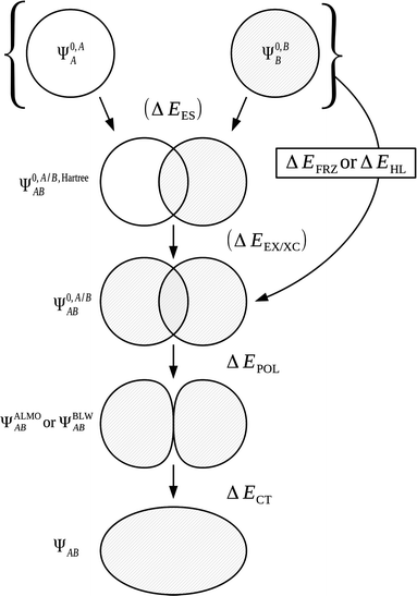
The decomposition of ΔE into these three energy components is shown within Fig. 5 and 6.
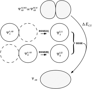 | ||
| Fig. 6 The treatment of charge transfer within the ALMO EDA1 and BLW EDA2 schemes. The (positive) BSSE is introduced to the charge transfer term because both BSSE and charge transfer are effects resulting from the delocalization of monomer MOs, caused by including basis functions from the neighbouring fragments. | ||
A relatively recent extension to the ALMO EDA130 has been developed that allows the isolation of forward and back charge donation quantities using the concept of chemically significant complementary occupied-virtual orbital pairs. The original ALMO EDA scheme also provides a treatment for the charge transfer back and forward donation energies. This involves performing a single non-iterative Roothaan step correction to estimate charge transfer between the fragments of the system, with a higher order correction included to ensure the fragment charge transfer energies add up to the full ALMO EDA charge transfer energy.1 Charge transfer has also been quantified in BLW EDA studies by Mulliken, Löwdin and natural population analyses.131–133 The ability to evaluate charge transfer quantities in addition to energies further enhances the picture of chemical bonding these methods provide.
4.4 Natural EDA
The NBO approach of Weinhold et al.71,72 is used as the basis in the NEDA3–6 scheme. The use of the NBO basis results in a wavefunction which follows the classic Lewis interpretation of bonds and lone-pairs. Although a number of the components of this scheme are similar to those within the KM EDA scheme, NEDA does not variationally optimize any of its intermediate wavefunctions and this results in a number of artefacts in the values observed when using the NEDA scheme that will be discussed later.4.4.1.1 The five-term NEDA. In the five-term NEDA scheme, the decomposition of the interaction energy is of the form,
| ΔE = ΔEES + ΔEPOL + ΔECT + ΔEEX/XC + ΔEDEF | (53) |
From the common charge densities described earlier, the (CP corrected) interaction energy may be expressed using energy functionals as,
| ΔE = E[nABAB] − E[n0,ABA] − E[n0,ABB] | (54) |
The intermediate charge densities used in the evaluation of the NEDA components are calculated after transforming the KS matrix of the supermolecule to the NBO basis. The charge density associated with the monomer A perturbed in the field of the other monomer B, nABA(r), is calculated from the variationally optimized AB supermolecule state and is expressed as,
 | (55) |
The localized (CT-restricted) charge density nloc,ABAB(r) is calculated from the charge densities associated with the individual perturbed monomers as,
| nloc,ABAB(r) = nABA(r) + nABB(r). | (56) |
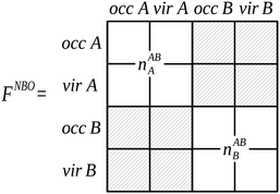 | ||
| Fig. 7 The partitioning of the NBO Fock matrix for the AB complex involved in the construction of the nloc,ABAB(r) charge density.4 Delocalizing interactions described by the hashed blocks of the Fock matrix are not included in this charge density construction, where the labels ‘occ’ and ‘vir’ denote the sets of orbitals that are occupied and virtual on the monomers A and B. | ||
From the charge densities described we can define the charge transfer (ΔECT) and deformation (ΔEDEF) components of the NEDA scheme as,
| ΔECT = E[nABAB] − E[nloc,ABAB] | (57) |
| ΔEDEF(A) = E[nABA] − E[n0,ABA] | (58a) |
| ΔEDEF(B) = E[nABB] − E[n0,ABB] | (58b) |
| ΔEDEF = ΔEDEF(A) + ΔEDEF(B). | (58c) |
Whilst the charge transfer and deformation components of the NEDA scheme implemented at the DFT and HF levels of theory are identical, differences exist in the interpretation of the remaining contribution to the interaction energy.6 The remaining contribution to the interaction energy given by eqn (54) is shown to be that of the interaction of the perturbed monomer charge densities,
| ΔE − ΔECT − ΔEDEF = E[nloc,ABAB] − (E[nABA] + E[nABB]). | (59) |
| ΔE − ΔECT − ΔEDEF = ΔEES + ΔEPOL + ΔEXC. | (60) |
The classical contribution to this remainder of the interaction energy can be expressed simply as,
 | (61) |
 | (62) |
 | (63) |
| ΔEXC = Exc[nloc,ABAB] − (Exc[nABA] + Exc[nABB]) | (64) |
 | (65) |
4.4.1.2 The self polarization energy term and the three-term NEDA. A penalty term associated with the energy cost to polarize the unperturbed monomers to their perturbed charge densities is also included within the NEDA scheme named the self (polarization) energy, (ΔESE).5 Interpretation of the ΔEDEF component is somewhat problematic as this component includes both the contribution of Pauli repulsions to the interaction energy, as well as the contribution from the self energy penalty. It is sometimes useful to separate these contributions as the isolation of this penalty energy from the ΔEDEF component allows the reduction of the interaction energy expression of eqn (53) into three components: an electrical interaction (ΔEEL), charge transfer (ΔECT), and core repulsions (ΔECORE).
The induced monomer charge density on monomer A, ΔnA(r), is defined as the difference in the charge densities associated with the perturbed and unperturbed monomer A,
| ΔnABA(r) = nABA(r) − n0,ABA(r). | (66) |
 | (67a) |
| ΔESE = ΔESE(A) + ΔESE(B) | (67b) |
| ΔEEL = ΔEES + ΔEPOL + ΔESE | (68a) |
| ΔECORE = ΔEDEF + ΔEXC − ΔESE | (68b) |
| ΔE = ΔEEL + ΔECT + ΔECORE. | (68c) |
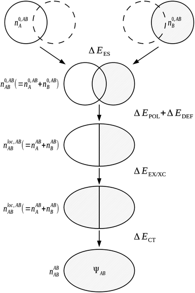
The five-term NEDA scheme can also be described schematically as within Fig. 10.
Significantly, the polarization term of the NEDA scheme is purely electrostatic in origin, while intramolecular electron exchange (or exchange–correlation) effects of polarization are captured within the deformation component ΔEDEF (Fig. 8), and the remaining intermolecular exchange contribution contained within a portion of the exchange component ΔEEX/XC.
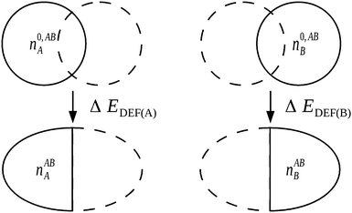 | ||
| Fig. 8 The evaluation of ΔEDEF for a complex AB. Non-classical effects of polarization are captured within the ΔEDEF component along with intrafragmental electrostatic energy effects.6 | ||
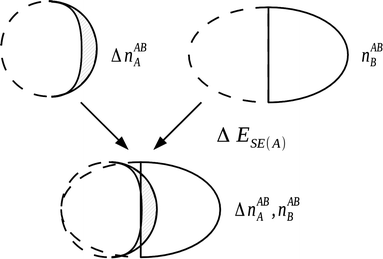 | ||
| Fig. 9 The evaluation of self energy component for a monomer A in the field of monomer B. This component is a portion of the deformation component that is electrical in origin, with the remainder of the deformation component resulting from Pauli repulsion contributions.5 | ||
4.5 Pair interaction EDA
The PIEDA24 scheme is a reformulation of the original KM EDA approach in the FMO description of Kitaura et al.32–35 The PIEs referred to by PIEDA are the interaction energies of the fragments produced, and for this reason PIEs are also known as interfragment interaction energies (IFIEs).87 The FMO prescription is one that is also naturally well suited to the analyses of large systems (such as proteins) and hence is of interest for the study of biomolecular systems.The FMO framework is implemented at many levels of theory, namely the RHF, DFT, second-order Møller–Plesset perturbation theory (MP2), CC, MCSCF, time-dependent DFT (TDDFT), and configuration interaction (CI) theories.88 This is also partially inherited within the PIEDA approach and the ability to access the MP2 and CC correlated levels of theories34,88 is of merit to the approach. The KM EDA-type energy components are however limited to evaluation at the RHF level of theory, with the addition of a dispersion term ΔEDI to ensure a correct representation of the interaction energy at these correlated levels of theories.
PIEDA is available in two types. The first type begins using the densities obtained by an FMO calculation. The FMO densities are already polarized by construction, and so PIEDA follows using the KM EDA components described within eqn (30) but without inclusion of the polarization component.35 Within PIEDA, the charge transfer component is also combined with the mixing component to produce the component ΔECT+MIX. An additional dispersion component ΔEDI is also included in the PIEDA decomposition. This is added in a straightforward manner when running a PIEDA calculation at the MP2 or CC levels of theory, and describes the correlation energy of these theories.88 PIEDA has also been developed for system calculations in solution.134 A solvation contribution ΔESOLV is calculated using an approach combining the polarizable continuum model (PCM) with the FMO framework known as PIEDA/PCM. This contribution describes the solvent screening of the PIEs and is important for obtaining meaningful interaction analyses.135 The full form of this PIEDA type is
| ΔEintIJ = ΔEES + ΔEEX + ΔECT+MIX + ΔEDI + ΔESOLV | (69) |
The second (full) type of PIEDA adds a polarization component ΔEPOL to the EDA components.88 The calculation of polarization requires an additional description of the free state of the fragments. For molecular clusters this is simply obtained as the molecules in isolation, however for systems that involve bond partitioning the description is ambiguous. The state for these bond partitioned fragments uses minimally possible caps, for example in the case of a C–C bond a methyl cap would be used.
The polarization energy is separated into a destabilizing contribution from the monomer internal energies EI′, and a stabilizing contribution from the electrostatic energy component ΔEES of the first PIEDA.24 A number of polarization coupling terms are included in this EDA, namely polarization–exchange, polarization–dispersion, polarization–charge transfer and many-body polarization terms.
5 Perturbation based energy decomposition analysis
The EDA schemes can be categorized by the nature of their underlying theory. The character of the schemes may be described as either variational in which the interaction energy is decomposed by use of intermediate wavefunctions, or alternatively as perturbation based in which the interaction between the fragments is seen as a perturbation to the non-interacting description, and the interaction is constructed as corrections resulting from different physical effects. In this section, we describe the SAPT and NBO second-order perturbation theory approaches for interaction energy analysis.5.1 Symmetry-adapted perturbation theory
The description of SAPT here will focus upon what is usually termed the SAPT(0) approach. The approach assumes the Møller–Plesset fluctuation operators, ŴA and ŴB, to not contribute to the interaction energy and provides a concise introductory description of the SAPT formalism.
The SAPT expression for the Hamiltonian of a complex AB is,
Ĥ = ĤA + ĤB + ξŴA + ηŴB + ζ![[V with combining circumflex]](https://www.rsc.org/images/entities/i_char_0056_0302.gif) | (70) |
 | (71) |
 | (72a) |
 | (72b) |
A symmetrized Rayleigh–Schrödinger (SRS) perturbative expansion with respect to the perturbation parameters ξ, η, and ζ defines the SAPT approach with the interaction energy expressed as,
 | (73) |
Within the SAPT(0) approach, the conditions of ξ = η = 0 are enforced. This results in an interaction energy SRS expansion of the form,
 | (74) |
The SAPT(0) interaction energy up to the second-order with renaming of terms (cf.eqn (73)) may be expressed as,
| ΔESAPT(0) = E(1)elst + E(1)exch + E(2)ind + E(2)exch. | (75) |
The second-order energy correction polarization term, E(2)ind, is formed of an induction and a dispersion contribution,
| E(2)ind = E(2)ind + E(2)disp | (76) |
| E(2)ind = E(2)ind(A ← B) + E(2)ind(B ← A) | (77) |
 | (78) |
 | (79a) |
 | (79b) |
 | (80) |
Substituting the SAPT(0) MOs with KS MOs in the above equations results in a method named SAPT(KS).142 The SAPT(KS) approach is noted however as failing to properly reproduce the dispersion energies of the original SAPT scheme.143–146 This scheme differs from the SAPT(DFT)143–146 approach in which the dispersion interaction of eqn (80) are obtained from frequency-dependent density susceptibility (FDDS) functions from TD-DFT calculations.
| Epol = E(2)ind,MCBS | (81a) |
| Ect = E(2)ind,DCBS − E(2)ind,MCBS | (81b) |
5.2 Natural bond orbital second-order perturbation theory analysis
A notable asset of the NBO package (of which NEDA belongs) is its ability to calculate second-order perturbation theory energies for a particular donor–acceptor NBO pair.85,120 This low-order perturbative correction provides an estimate for the charge transfer contribution of an NBO pair (from a bonding to an anti-bonding NBO) to the total interaction energy. This energy is expressed by the equation, | (82) |
6 Applications of energy decomposition analysis
We have investigated a number of systems of interest within the field of drug design. These model systems express key interactions typically found within ligand–host systems, such as hydrogen bonding, π–π and halogen interactions. The test systems we have included for study have been selected based on their relevance to biomolecular studies whilst maintaining small size. The chosen series are important to understanding trends in the EDA results and to correlate these with chemical common sense. Of key consideration in drug design are effects resulting from hydrogen bonding and dispersion interactions.148,149 We have included a number of systems in our work that express these interactions. We have arranged these systems into 6 congeneric series test sets that are expected to follow key trends in bonding character.We aim to identify the EDA approaches which are most suitable for biomolecular applications by considering a number of criteria. These criteria include the schemes' abilities to describe the interaction energy with chemically useful energy components, physically reasonable energy values, and with minimal basis set dependence. The EDA schemes investigated in the present study were the ALMO EDA, NEDA, KM EDA, RVS EDA and SAPT(KS) schemes. The PIEDA scheme was deemed inappropriate for the study of our test systems as this scheme is essentially identical to the KM EDA for molecular fragments. Also, because the NBO second-order perturbation theory is a charge transfer analysis tool and not a variational or perturbation EDA scheme we have not included results of this approach in our work.
6.1 Calculation set-up
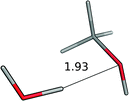
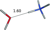
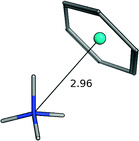
Starting geometries were chosen with the expectation that the test sets would ideally follow a congeneric trend on geometry optimization. Geometry optimization was performed at the BLYP-D3/6-311G* level of theory on all structures using the NWChem ab initio package.150 The -D3 correction for dispersion of Grimme et al.151 was used in order to properly model the dispersion interactions especially observed in the case of the π–π interacting systems. The BLYP functional was chosen due to its minimal mean absolute deviation (MAD)151 for the S22 benchmark dataset152 when using the -D3 correction.EDA was subsequently performed on the geometry optimized structures at the same BLYP-D3/6-311G* level of theory at which the geometries were optimized for the ALMO EDA, NEDA and SAPT(KS) schemes, and at the HF/6-311G* level for the KM EDA and RVS EDA schemes. The KM EDA polarization component does not obey the Pauli principle and it is possible for valence electrons to collapse into the partner fragment's core orbitals.95–97 To prevent this and to allow energy convergence, the calculations of the KM EDA and RVS EDA components for the benzene–Li+ system were performed without d polarization functions on the lithium atom. The optimized geometries of the systems studied using EDA are shown within Table 1, and further information of preparation of the systems in test set 6 is provided.‡
| System | Figure |
|---|---|
| a The benzene–ammonium system of test set 3 is also contained within test set 4. b DMA is dimethylacetamide. | |
| Test set 1: hydrogen bonding interactions | |
| Water–water |

|
| Water–methanol |
|
| Methanol–methanol |

|
| Water–ammonia |

|
| Test set 2: water–cations | |
| Water–ammonium |
|
| Water–Li+ |

|
| Water–Na+ |

|
| Water–K+ |

|
| Test set 3: ammonium–π systems | |
| Ammonium–benzenea |
|
| Ammonium–thiophene |
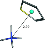
|
| Ammonium–furan |
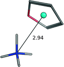
|
| Ammonium–pyrrole |
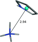
|
| Test set 4: π-cations | |
| Benzene–ammoniuma |
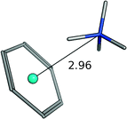
|
| Benzene–Li+ |

|
| Benzene–Na+ |
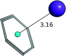
|
| Benzene–K+ |
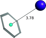
|
| Test set 5: π interacting systems | |
| Benzene–benzene (T-shaped) |
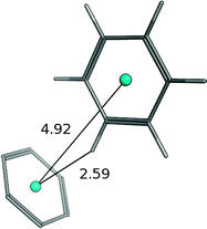
|
| Benzene–benzene (parallel displaced) |

|
| Benzene–pyridine |

|
| Benzene–pyrimidine |
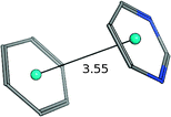
|
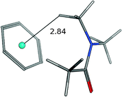
| Benzene–DMAb |
|
| Test set 6: halogenated systems | |
| Benzene–fluorobenzene |

|
| Benzene–chlorobenzene |

|
| Benzene–bromobenzene |

|
NEDA, KM EDA and RVS EDA calculations were performed on the structures using the GAMESS-US153ab initio package and ALMO EDA and SAPT(KS)141,154 calculations were performed using the Q-Chem155 package. The locally-projected SCF equations of Gianinetti77,78 were used in the ALMO approximation of the ALMO EDA, and partitioning of the charge transfer and polarization components of the SAPT(KS) approach from the induction energy was achieved using eqn (81a) and (81b).
6.2 Results and discussion
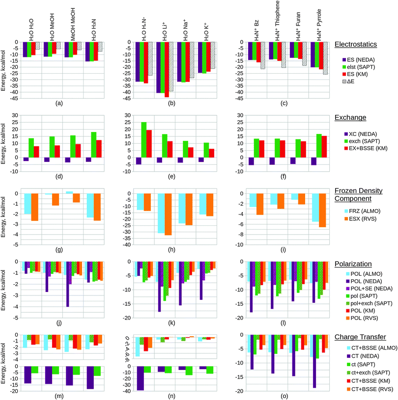
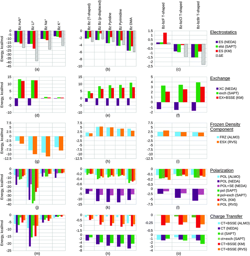
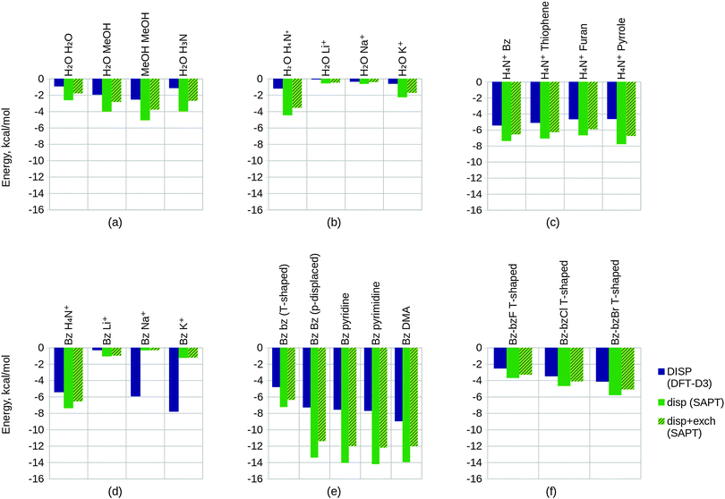
Within this section, we compare the trends of the various EDA components within each congeneric series. Our goal is to examine the chemical relevance of each EDA method for the different series. An ‘ideal’ EDA would be expected to produce results that agree with chemical intuition in obvious cases and produce sensible energy components in more difficult cases where chemical intuition is less obvious. Plots of the EDA results for the test sets are given in Fig. 11 and 12.In Fig. 11(a) we observe that the electrostatics of the water dimer, water–methanol and methanol dimer systems are similar (within 0.52 kcal mol−1 at the NEDA/SAPT(KS) level and 1.05 kcal mol−1 at the KM EDA level), and that the water–ammonia system electrostatic energy is more stabilizing than the water–methanol system by 3.81 kcal mol−1 at the NEDA/SAPT(KS) level and 5.44 kcal mol−1 at the KM EDA level. We would expect that as oxygen is more electronegative than nitrogen this would give rise to a greater dipole moment than for the final nitrogen containing ammonia interacting system and hence a higher electrostatic component for the first three systems. The oxygen containing molecules also possess 2 lone pairs rather than the 1 lone pair found on the nitrogen of ammonia, and this would also support expectations of a lower electrostatic component for the ammonia interacting system. This trend therefore contradicts our chemical expectations. A similar yet opposite in sign trend is observed for the exchange component of Fig. 11(d), with the ΔEFRZ and ΔEESX terms showing the electrostatic energy to be more dominant than exchange by similar amounts for the water dimer and water–ammonia systems. Polarization (displayed in Fig. 11(j)) is shown to become more stabilizing across the set fairly consistently, with a gain observed in stabilization from the methanol dimer to the water–ammonia system for all but the NEDA (0.41 kcal mol−1 to 0.68 kcal mol−1 increase in stabilization for all other schemes). For the NEDA of these two systems, polarization (with the self-energy correction) is shown to be less stabilizing by 1.08 kcal mol−1 for the water–ammonia system. This may be due to a number of reasons including lack of variational optimization of the intermediate wavefunctions of NEDA.
We expect charge transfer to be increasingly dominant across the first three systems due to increasing presence of the electron donating methyl substituents. This is shown in Fig. 11(m) and is noted to increase consistently and at a slower rate than for the polarization component across these systems. Charge transfer for the ammonia system is expected to be similar to the water dimer system due to its similar size. Due to the greater electronegativity of oxygen in comparison to nitrogen, we may expect charge transfer to be greater from the ammonia molecule due to its greater ability for electron donation. These features are also observed, with charge transfer indicated as falling for the final water–ammonia system by all schemes but the NEDA and SAPT(KS). For all but the RVS EDA scheme, charge transfer effects are greater for the water–ammonia system than the water dimer system. The NEDA values for charge transfer are also noted as being excessively large (up to −18.35 kcal mol−1), almost an order of magnitude larger than the other methods and do not appear chemically credible.
The results suggest electrostatics to be the most dominant driving force of hydrogen bonding, with exchange greatly countering this contribution. Charge transfer remains the next most dominant driving force, except for the SAPT(KS) for which on including exchange corrections the polarization component is slightly more dominant across the set (up to 0.49 kcal mol−1 more dominant). Overall our results therefore suggest the hydrogen bonding interactions of this set to be characterized by dominance of the electrostatic energy component but with significant contribution from the charge transfer component and minimal polarization contribution. This is a very interesting observation as hydrogen bonds are often described by necessity (e.g. force-fields) as arising only due to electrostatics without involvement of charge transfer effects. Notably, Weinhold and Klein164 recently characterized a set of hydrogen bonding complexes in which the electrostatic interaction is interpreted as repulsive. Such “anti-electrostatic” hydrogen bonding complexes include interacting fluoride and bicarbonate anions, with the hydrogen bond presence evidenced by near linearity of the FHO unit bond (157.1°), significant vibrational red shift at νOH, Bader's QTAIM26 analysis and natural bond critical point analysis. There exists a significant repulsive penalty in order to form the bond (56.75 kcal mol−1 at the B3LYP/aug-cc-pVTZ level), with a shallow metastable “hydrogen bond” local minimum ΔE = −0.05 kcal mol−1. This is also further supported by our own ALMO EDA calculations at the B3LYP/aug-cc-pVTZ level and using the same geometry as Weinhold and Klein, in which we observe a strongly repulsive frozen density interaction of 64.27 kcal mol−1 with relatively small polarization (−8.49 kcal mol−1) and charge transfer (−3.81 kcal mol−1) contributions. A re-examination of the electrostatic and resonance phenomena of this system by Frenking and Caramori165 using the ETS EDA29–31 at the B3LYP-D3/TZ2P+ level gave a deeper energy well (−0.77 kcal mol−1) which was interpreted as a stabilizing electrostatic interaction. In reply to Frenking and Caramori, Weinhold and Klein166 argue that their viewpoint is different. This is a clear example that within the chemistry community a variety of EDA interpretations are in use which are not always compatible. This class of systems demonstrates the complex nature of hydrogen bonding (and equally the complex nature of EDA interpretations also), and shows that the presence of stabilizing electrostatic interactions may not be necessary for hydrogen bonding between molecules.
The trend in exchange (which may include both processes of electron exchange and implicit orbital orthogonalization, and hence describe a Pauli repulsion-type contribution) shown in Fig. 11(e) remains slightly less clear in its origin, as factors of intermolecular distance, electron count and energy costs of orthogonalization all contribute to the value of this component. Nonetheless, we can rationalize the EDA results as both the energy cost of orthogonalization and the exchange itself decay with increasing intermolecular distance.
For the alkali metals, we expect polarization to be most significant for the lithium interacting system due again to the strong electrostatic energy interaction seen for this system as discussed above. The lithium ion is the smallest of the metals and hence is able to approach the water fragment more closely. We would therefore expect this ion to be able to polarize the water molecule charge density more effectively than the remaining metals. This trend is observed within the EDA results as shown in Fig. 11(k).
Polarization is observed to be less stabilizing for the ammonium interacting system than for the lithium interacting system, whilst charge transfer is conversely observed to be the most stabilizing (excluding SAPT(KS)) for the ammonium interacting system as shown in Fig. 11(n). The decrease in polarization contribution is possibly a result of the increased r(O–N+) distance in comparison to the r(O–Li+) distance, and the greater charge transfer contribution of this system may arise through the ability of the ammonium molecule to diffuse its charge over a much larger volume than the alkali cations.
For the charge transfer component of the alkali metals, we again expect the properties of the lithium ion to be significant in determining the trend observed. We would expect the lithium ion to be more effective at withdrawing charge from the partner water molecule, and hence expect the EDA results to display a more stabilizing charge transfer component for the lithium ion that decreases down the group 1 metals. This is observed to an extent in Fig. 11(n): between the lithium and sodium ion interacting systems the charge transfer contribution falls for all but the SAPT(KS) scheme without the exchange correction. We also note that for the RVS EDA scheme the charge transfer energy is positive and unphysical for these two systems (0.05 kcal mol−1 and 0.34 kcal mol−1 for the lithium and sodium ion interacting systems respectively), seemingly through overcorrection by the CP correction. Interestingly, we observe charge transfer to increase between the sodium and potassium ion interacting systems for all but the NEDA and SAPT(KS) schemes. It is unclear why this is observed, however through the analysis of the charge transfer BSSE contributions of the schemes that display this unexpected trend it appears that the increase also arises due to an artefact of these schemes' CP corrections.
The charge transfer KM EDA component is indicated as increasing for the final water–potassium system. This observed break from the trend may be due to the known instability of the KM EDA with larger basis sets and smaller intermolecular distances,95–97 whereby a state with occupied orbital occupation number greater than 2 is possible. Whilst the water–cation distance is the greatest for the potassium system, the increase in the extension of the 6-311G* basis with the extra electron shell may be large enough to give rise to this artefact of the KM EDA scheme. This highlights the contradictory observation that using an incomplete basis set with the KM EDA can give rise to results with more physical relevance.
We would chemically expect the vast majority of polarization to result by effect of the ammonium ion on the aromatic fragment. Aschi et al.16 support this expectation quantitatively with greater than 98.5% of polarization contributed by the aromatic fragment and describe the polarization interaction as “exclusively an ion-induced multipole interaction”. Polarization is observed to fall slightly (up to 0.59 kcal mol−1) between the benzene and thiophene interacting systems, and again between the thiophene and furan interacting systems (up to 1.31 kcal mol−1). For the pyrrole interacting system polarization is observed to increase in stability. The NEDA scheme predicts this stability increase to be small (0.23 kcal mol−1) with the contribution of polarization lying between the thiophene and furan contributions. However, for the remaining schemes this is suggested to be more significant, with the polarization contribution of the pyrrole interacting system the greatest for this set.
The magnitude of charge transfer effects is dependent on the electron donating ability of the aromatic system. Based purely on the electronegativities of carbon, sulphur, oxygen and nitrogen (and therefore their electron donating ability into the aromatic ring), we would expect charge transfer to the ammonium to be of the order furan < pyrrole < benzene = thiophene. Our expectations using this model partially confirm this, with the trend supporting similar charge transfer values for the benzene and thiophene interacting systems, and smaller furan charge transfer than for pyrrole. Our model does not account for the less clear effects resulting from the aromatic geometries and constituents however, and this may be the reason for the inaccuracy of our expectations. For the ALMO, KM and RVS EDAs and SAPT(KS), charge transfer is indicated as within a reasonably small range across the set (within 2.60 kcal mol−1) but increasing significantly from −12.33 kcal mol−1 to −18.89 kcal mol−1 for the NEDA scheme. This large range of NEDA charge transfer energies is unexpected and indicates a lack of stability of this component.
Exchange effects (Fig. 12(d)) are expected to be generally less significant than for test set 2 due to the greater intermolecular distances of the systems of test set 4. This is observed across the set, notably however exchange is not shown to fall in a consistent manner. This observation possibly arises due the comparatively small intermolecular benzene–lithium separation that results in a greater exchange component.
Polarization within test set 4 (Fig. 12(j)) is shown to be approximately twice the magnitude of polarization within test set 2 (Fig. 11(k)). This observation is explained from a chemical perspective by the greater polarizability of benzene (α = 10.74 Å3) in comparison to water (α = 1.45 Å3).167 The polarization component of the lithium interacting system is shown to stabilize the system by more than 400 kcal mol−1 through the KM EDA using the 6-311G* basis set. Removing d polarization functions from the lithium basis reduces this component to a more reasonable value (−25.86 kcal mol−1). This artefact is believed to originate in the ability of valence electrons to collapse from one fragment into the core orbitals of the other fragment, enabled through the use of intermediate wavefunctions that do not satisfy the Pauli exclusion principle.95–97 As the completeness of the basis set increases, the polarization component becomes extreme in magnitude as this process of collapse becomes more significant. We have also included results using the balanced 6-311G basis set in the ESI.† These results support the use of the modified unbalanced basis as reliable as an approximation to the 6-311G* basis used in the remaining calculations.
Interestingly, charge transfer (Fig. 12(m)) does not follow the same trend as within test set 2 (Fig. 11(n)) and the ammonium and lithium cations are reversed in their charge transfer contribution trends. This observation is expected, as the hydrogen atom of the ammonium molecule interacting with benzene is directed into the low electron region of the π cloud whereas for the water–ammonium system an ammonium hydrogen atom is directed towards the oxygen of the water molecule.
Charge transfer within the benzene–lithium system is indicated as highly contributing in comparison to the systems of the other sets. This contribution is possibly due to the cation being able to access the electron-rich π cloud of the benzene by siting itself within this on binding, and due to the charge of the cation interacting with the benzene. A more rapid decrease in charge transfer contribution with increasing cation mass is observed than for the water–cation systems of test set 2. This may be a result of the geometry of the set: the rate of fall in intermolecular distance across the π–cation set (1.90 Å range of r) is greater than across the water–cation set (0.77Å range of r).
A number of predictions can be made based on the compositions of the structures of study. We would expect the energy components to increase in magnitude when going from the benzene T-shaped to the parallel displaced conformers due to the smaller intermolecular distance between the molecules. Generally this is observed in the results. Notably, however, stabilization through the KM EDA electrostatic component is shown to fall by over 1 kcal mol−1 as shown in Fig. 12(b). The charge transfer components of the ALMO EDA and SAPT(KS) (with exchange correction) schemes are also observed to fall fractionally between these two systems as shown in Fig. 12(n), however these energy changes are so small that they may be considered negligible.
The three π–π interacting parallel displaced systems are structurally very similar and so deducing the expected component trends for these systems is slightly less clear. With an increase in the number of nitrogen constituent atoms on the interacting molecules we observe an increase in charge transfer effects, as also shown in Fig. 12(n). This is expected: with increased substitution through benzene, pyridine and pyrimidine the electron withdrawing abilities of these molecules also increase, and so are able to withdraw more charge density from the π cloud of the partner benzene molecule. In considering polarization effects within these three systems, we would expect a more significant electric moment in the plane of the benzene interacting system with increased substitution to provide a more polarizing field for the benzene molecule. Polarization across these three systems is predicted to be enhanced through this effect. However, the polarizabilities of these molecules themselves are shown to fall across the three systems (α = 10.74 Å3, 9.15 Å3 and 8.53 Å3 for benzene, pyridine and pyrimidine respectively),167 and so the final polarization contribution becomes a balance of these two opposing factors of polarizability and field strength. As shown in Fig. 12(k), polarization falls across the three systems for all but the NEDA scheme, therefore indicating that the effect of falling polarizabilities outweighs the effect of more significant polarizing electric fields for the benzene.
For the final DMA interacting system, we observe moderately increased electrostatic and exchange energy contributions as shown in Fig. 12(b) and (e) respectively. This is interesting to note as the DMA molecule to benzene distance is similar to the intermolecular distances seen within the other systems. We may expect a greater polarization contribution for this system due to the more extended structure of the DMA molecule in comparison to the cyclic structures of the other interacting systems. This is supported by the results shown in Fig. 12(k) for all but the NEDA scheme. We expect the proton positioned above the π cloud to act as a means for electron transfer to the DMA molecule, with the oxygen acting as an electron sink stabilized through resonance of the amide bond. As a result of this, we predict charge transfer to be greater for this system. This is observed for all but the HF level schemes (KM and RVS EDA), as shown in Fig. 12(n).
We predict the electrostatic energy to increase from the fluorobenzene interacting system through to the bromobenzene interacting system. This is because going through the series the charge on the halogen becomes more positive, and so the electrostatic interaction of the halogenated benzene molecule with the quadrupole of the benzene will become more favourable. We expect the σ hole on the chlorine and bromine atoms to enhance this effect, as the positive potential on these atoms is therefore concentrated to a region on the halogen that gives a more favourable electrostatic interaction with the benzene π cloud. In fact, due to lack of a σ hole on the fluorobenzene molecule we may expect the electrostatic interaction in this system to be destabilizing. We also expect the increasing intermolecular distances through the series to contribute to a decrease in electrostatic component energy magnitudes. This factor opposes our expectations of increasing electrostatics through the series due to increasing halogen charge. The electrostatic component results are shown in Fig. 12(c). It appears that the increase in electrostatics through the series arises due to increasing halogen charge, which more than compensates for any weakening of this component through increased intermolecular distance.
The exchange component is expected to fall through the series due to increased intermolecular separation of the molecules. As halogen electronegativity decreases through the series, we expect the charge on the halogenated benzene molecule to become more localized on the π ring. This is expected to additionally reduce the contribution of exchange, as exchange is distance dependent and the electrons are now further from the partner benzene molecule. We observe a slight fall in exchange that is in agreement with our predictions between the fluorinated and chlorinated systems as shown in Fig. 12(f). However, exchange is approximately as strong for the brominated system as the fluorinated system. This arises due to the greater number of electrons on bromobenzene than on fluorobenzene. With more electrons on the bromobenzene available to exchange with the benzene electrons, the exchange interaction for bromobenzene can therefore be stronger despite the greater intermolecular separation for this system.
Whilst polarization effects are expected to increase through the set as a result of increasing polarizabilities of the halogenated benzene molecules, the increase in intermolecular separations of the systems is also expected to have an impact on this component. The polarizability of fluorobenzene (α = 10.3 Å3) is less than that of chlorobenzene (α = 14.1 Å3) and bromobenzene (α = 14.7 Å3).167 However, the benzene π ring to halogen distance is more than 0.42 Å shorter for the fluorinated system than for the chlorinated and brominated systems as shown in Table 1. The enhancement of polarization through the smaller benzene–fluorobenzene intermolecular separation could be reasonably similar to the enhancement in the benzene–bromobenzene through the effect of greater bromobenzene polarizability, however we cannot predict by chemical reasoning alone which factor dominates. The intermolecular separations of the chlorinated and brominated systems are reasonably similar, and we expect that polarization effects will be greater in the brominated system than the chlorinated system solely as a result of differences in molecular polarizabilities. The polarization results are shown in Fig. 12(l). The NEDA results show polarization to be smallest for the fluorinated system (−1.22 kcal mol−1 with the self-energy correction), indicating the smaller intermolecular separation within this system to offer little enhancement to polarization. However, NEDA overestimates polarization by an order of magnitude compared to the other schemes. More importantly all other schemes show polarization to be slightly greater for the fluorinated system and therefore instead indicate the smaller intermolecular separation to enhance polarization to a small degree. Our prediction of increased polarization from the chlorinated system to the brominated system is in agreement with all the EDA scheme results.
We expect the presence of a σ hole on the chlorine and bromine atoms to enhance charge transfer to a degree in these systems. This is due to the σ holes being located in the high electron region of the benzene π ring. We predict the strongly electron withdrawing nature of the fluorine atom to be more important than the presence of a σ hole in enhancing charge transfer effects. Also, the smaller benzene–halogen separation in the benzene–fluorobenzene system (2.97 Å) is also expected to enhance charge transfer effects in this system. The intermolecular separation is slightly greater within the bromobenzene system than within the chlorobenzene system, and chlorine is more electronegative than bromine. We therefore predict the charge transfer interaction to be weaker for the bromobenzene system than the chlorobenzene system. Our results of charge transfer for this test set are shown in Fig. 12(o). The results of the SAPT(KS) scheme shows charge transfer to increase in strength going through the set from the fluorinated system to the brominated system. This indicates charge transfer to be weakest in the benzene–fluorobenzene system despite this system's smaller intermolecular separation and the greater electronegativity of the fluorine atom compared to the other halogens, and therefore suggests the presence of a σ hole to be significant in determining charge transfer in these systems. The other schemes generally show similar or greater charge transfer effects for the fluorinated system than for the brominated and chlorinated systems. These schemes therefore instead suggest the presence of a σ hole on the halogen to contribute at least slightly to charge transfer effects in the chlorinated and brominated systems. All schemes show an increase in charge transfer between the chlorinated and brominated systems, confirming our predictions for these two systems.
The dispersion interaction arises as a result of instantaneous polarization dipoles in the monomers forming and interacting. We would therefore expect greater dispersion contributions for systems where both monomers have high polarizabilities, as this would enable larger instantaneous dipoles to arise. Chemically this component is also highly dependent on the intermolecular separation R, with its magnitude decaying as R−6.
For test set 1, we expect the determining factor of the trends to be the molecular polarizabilities. This is because the intermolecular separations observed in this set are similar, as shown in Table 1. The polarizability of methanol (α = 3.29 Å3)167 is more than twice that of water (α = 1.45 Å3)167 and therefore an increase in dispersion across the first three systems of this set is expected. The polarizability of methanol is greater than that of ammonia (α = 2.10 Å3)167 and so we would expect dispersion within the water–methanol system to be greater than within the water–ammonia system. The results of the dispersion component for these systems are shown in Fig. 13(a), and our predictions are generally confirmed. We note that our prediction of a greater dispersion component for the water–methanol system than the water–ammonia system is observed in the results of the -D3 component, however for the SAPT(KS) scheme dispersion remains nearly constant between these two systems.
We expect the induced electric dipole moment of the ammonium molecules to be greater than for the metal cations for test set 2. This is because despite the presence of more diffuse electrons on the metal cations, the ammonium molecule is much larger and so we expect a larger dipole for this molecule to be able to be induced. The intermolecular separations of the ammonium molecule and metal cations are similar as shown in Table 1, and we therefore predict dispersion for the ammonium interacting system to be the strongest. This is confirmed by the results by both dispersion methods as shown in Fig. 13(b). In this set the intermolecular distance between the potassium ion and the water molecule is 0.77 Å greater than for the lithium ion interacting system. As dispersion forces are very close range interactions decaying as R−6, this component would fall to less than 1/8th of its original size if this geometric displacement were applied to the lithium ion. The polarizability of a potassium atom (α = 43.4 Å3)167 is nearly twice that of lithium (α = 24.33 Å3)167 and we expect the difference in polarizability of their ions to be similar in size. We would therefore expect that the strong dependence on intermolecular distance for dispersion outweighs the greater polarizability of potassium, resulting in a fall in dispersion across the set. Interestingly, however, the opposite is observed in our results and dispersion instead increases across the set.
As previously stated for our analysis of the remaining energy components of test set 3, we expect the systems of this set to display similar dispersion energy values due to the similar geometries and compositions of the structures. The polarizabilities (α) of benzene,167 thiophene,169 furan169 and pyrrole170 are 10.74 Å3, 9.96 Å3, 7.20 Å3, and 8.27 Å3 respectively. We therefore expect a slight fall in dispersion contributions from benzene to furan, and for pyrrole to have a dispersion energy value between thiophene and furan. The results for this set shown in Fig. 13(c) are in close agreement with our predictions, however for the final pyrrole interacting system we observe a greater than expected contribution by the SAPT(KS) approach and a slightly lesser than expected contribution by the -D3 component.
We expect the systems of test set 4 to show similar dispersion component values to the systems of test set 2 because these sets differ only through the interaction of benzene rather than water. Our expectations for test set 2 were of a greater dispersion energy for the ammonium interacting system, and a decrease in dispersion through the metal cation interacting systems due to the significant intermolecular dependence of dispersion. The increase in intermolecular distances through the metal cation interacting systems of test set 4 is much greater than in test set 2, and so we expect an even greater fall in dispersion through these systems in test set 4 than in test set 2. Our prediction of a greater dispersion component for the ammonium interacting system is supported by the results shown in Fig. 13(d), however the trends observed for the remaining metal cation interacting systems are significantly less supportive. In comparison to the results of the metal cation interacting systems of test set 2 (Fig. 13(b)), the greater increase in intermolecular distance through test set 4 appears to cause a comparatively weaker contribution of dispersion to the potassium interacting system by the SAPT(KS) scheme. Interestingly the opposite is shown for the -D3 component, with this energy unexpectedly increasing significantly across the metal cation interacting systems of test set 4 despite the rapid increase in intermolecular distances.
We note a significant dispersion contribution for the systems of test set 5 as shown in Fig. 13(e). This is expected considering the π interacting chemical nature of these systems. For the SAPT(KS) results of the benzene dimer, dispersion for the parallel displaced conformation is almost double than when in the T-shaped conformation. This is rationalized by the fact that the sum of the intermolecular atomic distances for the parallel displaced benzene dimer system is less than in the T-shaped system. It is also noted that the parallel displaced benzene dimer system features close proximity of the π rings of the benzene molecules. This is also expected to contribute to the dispersion interaction. For the three π–π interacting parallel displaced systems our chemical expectations are mixed. Polarizability is noted to fall from benzene to pyrimidine (α = 10.74 Å3 and 8.53 Å3 respectively167), and so we expect dispersion to fall across these benzene interacting molecules. However, the fall in intermolecular distances across these systems is expected to enhance the contribution of the dispersion energy due to its significant dependence on this parameter. The increase in dispersion across these three systems indicates that the decrease in intermolecular distances is more significant than the fall in polarizabilities of the molecules. For the DMA interacting system, we expect dispersion to be approximately as contributing as in the other systems. However it is difficult to give a precise prediction of this system's relative value due to the many possible chemical factors that affect dispersion. There exists delocalized π systems in all the molecules of this set. In DMA the presence of this feature is in the delocalized amide bond, and for the remaining molecules this is in their aromatic π rings. However, for DMA the amide bond is located further away from the π ring of benzene and so dispersion resulting from this delocalized feature is expected to be smaller. The structure of DMA is noted to be more extended than the other molecules in this set, and therefore greater dipoles are expected to be able to be induced in this molecules. This factor would be expected to favour a greater dispersion contribution in this system. The intermolecular separations of the systems (excluding the T-shaped benzene dimer system) are similar and therefore the balance of the above two features is difficult to predict. For the -D3 component dispersion is shown to increase moderately, whereas for the SAPT(KS) scheme this component falls by at most only 0.25 kcal mol−1.
Within test set 6 we expect dispersion to be most contributing in the fluorinated system, followed by the chlorinated system, and finally the brominated system. The polarizabilities of chlorobenzene (α = 14.1 Å3) and bromobenzene (α = 14.7 Å3) are similar, with the polarizability of fluorobenzene much smaller (α = 10.3 Å3).167 However, the intermolecular separation for the fluorinated system (5.69 Å) is also smaller than for the chlorinated (6.50 Å) and brominated systems (6.75 Å), as also shown in Table 1. Due to the significant dependence of dispersion on distance we expect dispersion to be relatively strong in the fluorinated system. For the chlorinated and brominated systems, we expect the chlorinated system to show the greater dispersion contribution. The strong dependence of dispersion on intermolecular separation combined with the similar polarizabilities of chlorobenzene and bromobenzene leads us to expect the chlorinated system to show a greater dispersion contribution than the brominated system. Our results shown in Fig. 13(f) display opposite trends to our predictions. The -D3 component shows an increase in dispersion from the fluorinated system (−2.54 kcal mol−1) to the chlorinated system (−3.50 kcal mol−1) and to the brominated system (−4.15 kcal mol−1). The SAPT(KS) results show an increase in dispersion from the fluorinated system to the chlorinated system of over 0.8 kcal mol−1, and from the chlorinated system to the brominated system of over 1 kcal mol−1. It is interesting to note the greater dispersion contribution shown by the EDA results for the benzene–bromobenzene system, and the less than expected dispersion contribution for the benzene–fluorobenzene system.
| EDA scheme | MO localizationa | Additional energy componentsb | Level of theory | Component artefacts and notes |
|---|---|---|---|---|
| a Localization methods include adopting an alternate basis to the MO basis (the NBO basis), an MO constraining method (ALMO), or a different energy calculation method (FMO). b Additional energy components to the electrostatics, exchange, polarization and charge transfer (or similar) interaction components. c Additional core repulsions (ΔECORE) and electrical interaction (ΔEEL) terms are also included in this scheme as combinations of other energy components of this scheme. d The PIEDA scheme is implemented at the HF level (as the basis of this scheme is the KM EDA), with the dispersion component added as an additional term, ΔEDI. e SAPT descriptions of polarization and charge transfer are calculated from the MCBS and DCBS induction energies (see eqn (81a) and (81b)). | ||||
| KM EDA | — | ΔEMIX | HF only | Presence of the ΔEMIX energy unascribable to any particular component. Problems of numerically unstable charge transfer and polarization energies with large basis sets and at short intermolecular distance.95–97 |
| RVS EDA | — | ΔEMIX | HF only | Unphysical ΔEMIX present. Typical magnitude is insignificant, but possible for non-negligible magnitudes to be seen. |
| ALMO | ALMO | — | HF/correlated | Combined electrostatics and exchange description of the frozen density component may reduce chemical insight. |
| NEDA | NBO | ΔEDEF, ΔESEc | HF/correlated | Theoretical overestimation of charge transfer and underestimation of polarization.1,11 Observed to provide unphysical charge transfer values. |
| PIEDA | FMO | — | HF/correlatedd | Shares similar theoretical weaknesses of the KM EDA. |
| SAPT(KS) | — | E (2)disp, E(2)exch–dispe | HF/correlated | Observed overestimation of polarization and underestimation of charge transfer. SAPT(KS) overestimation of second-order energy components (induction and dispersion) with the B3LYP functional.142 |
6.2.8.1 General observations. The CP correction is known to overestimate the BSSE171,172 and many of the schemes we have included in our investigation apply the CP correction to energy terms. It is important to note that as a result this correction has the potential to give rise to unphysical results, as is observed in the case of the charge transfer energies in the group 1 metal ion interacting systems of test set 2 for example. Overcorrection of the RVS EDA charge transfer energies results in a positive and unphysical energy for the lithium and sodium ion interacting systems, as shown in Fig. 11(n). Also, on applying the CP correction to the ALMO, KM and RVS EDA scheme charge transfer energy components the trend between the sodium and potassium ion interacting systems reverses. This serves to highlight the possible issues that may arise when applying the CP correction to EDA energy components.
6.2.8.2 KM EDA. The KM EDA7,90 requires an unphysical residual mixing term ΔEMIX to account for the difference between the energy components and the total interaction energy. This is a significant weakness as the mixing component values are at times observed to be of the same magnitude as the chemically meaningful terms. For example when including BSSE corrections, in the case of the metal cation interacting systems of test set 2 the mixing component is greater than the charge transfer term, and for test set 6 this component is greater than the magnitude of the polarization term. Attempts to reduce this problem have been discussed and implemented within the RVS and CSOV schemes, and the problem altogether avoided in other schemes such as the ALMO EDA and NEDA.
Numerical instability problems of the charge transfer and polarization energies with large basis sets and at short intermolecular distances95–97 are evidenced in our results. For the benzene–Li+ system of test set 4 convergence issues are observed when using the 6-311G* basis set. For this system the intermolecular separation is particularly small (1.88 Å) and gives rise to unphysical polarization and mixing component energies. This is likely due to valence electrons collapsing from one fragment into the core orbitals of the other fragment.95–97
6.2.8.3 RVS EDA. The RVS EDA13,99 is similar to the KM EDA, but with modification to the calculations of the polarization and charge transfer energies to use fully antisymmetric wavefunctions in attempt to remedy the numerical instability problems associated with these components in the KM EDA.
The ΔEESX component of the RVS EDA scheme (and similar ΔEFRZ component of the ALMO scheme) presents a problem in terms of the analytic information provided. This is because this energy component conceals the magnitudes of its electrostatic and exchange parts. The combined term does however provide useful indication of the dominance of its parts. For example, if this component is highly repulsive this might indicate Pauli repulsions to be significant. Avoiding the use of Hartree product intermediate wavefunctions involved in expressing the separated components may be desired, however, due to it not obeying the Pauli principle.
The RVS EDA scheme shares a component of the KM EDA that describes a residual energy to the interaction energy. In our calculations the magnitude of the RVS mixing component is typically less than 0.1 kcal mol−1 and therefore much smaller than the KM EDA mixing component. However, for systems containing an ammonium molecule the RVS mixing component is noted to increase significantly, for example the ammonium–pyrrole system of test set 3 has an RVS mixing component of −0.44 kcal mol−1. Whilst the magnitude of this term is only a fraction of the KM EDA mixing term (3.76 kcal mol−1 with BSSE correction), this does indicate that a notable level of ambiguity can still remain in the origin of a proportion of the interaction energy. Overall, however, the magnitude of the mixing term for any given system is more often than not negligible, and this helps to correct a major weakness of the KM EDA.
In the RVS EDA scheme the BSSE is only partially treated and this may be considered a weakness of the scheme. The interaction energy that is obtained in this scheme omits the exchange BSSE correction of eqn (36a) and (36b) that is treated in the KM EDA. By adopting the KM EDA BSSE correction for the exchange component, it is possible to remedy this. This is possible because the origin of the exchange component energy of these two schemes are the same, and so the RVS exchange energy is compatible with this BSSE correction and will give the fully BSSE corrected interaction energy.
6.2.8.4 ALMO EDA. The ALMO EDA scheme1 used in our calculations provided overall chemically sensible results. There are two possible disadvantages we note of this scheme however. Firstly, as discussed regarding the ΔEESX component of the RVS EDA scheme above, the ALMO EDA ΔEFRZ component similarly has the potential to be limited in the analytic information it provides. Secondly, it is theoretically possible for the charge transfer contribution to be repulsive on inclusion of the CP BSSE correction. This is because the CP correction has a tendency to overestimate the BSSE171,172 as discussed above. As noted by Mo et al.,11 it may be appropriate to consider the ALMO (and BLW) EDA charge transfer energies with and without the BSSE energy correction as the upper and lower bounds of this energy. Our results otherwise show the ALMO EDA scheme to consistently provide results in good agreement with chemical expectations.
6.2.8.5 NEDA. Our calculations using the NEDA scheme3–6 have shown this to give often very large charge transfer and polarization energy contributions. Theoretically the NEDA scheme is expected to generally overestimate charge transfer contributions and underestimate polarization.1,11 This is because in NEDA, the polarization and charge transfer terms are calculated from the monomer and supermolecule charge densities without variational optimization to an intermediate state. If we consider an alternative scheme such as the ALMO EDA scheme (in which an intermediate state is produced in a constrained optimization procedure) we can see that the NEDA description of the intermediate state is likely less desirable.
Another key observation of the NEDA scheme is its description of polarization effects. The polarization term includes only electrostatic contributions as shown in eqn (63), and the exchange contribution is contained within the deformation component. Furthermore, an electrostatic self energy penalty is also included in the NEDA scheme that describes the energy cost of charge polarization. This partitioning of polarization in NEDA may be advantageous or not depending on the situation at hand.
6.2.8.6 SAPT(KS). The results of the SAPT(KS) scheme139,140 are observed to remain in keeping with the trends shown by the other schemes and generally show chemically relevant magnitudes. Polarization energies of the SAPT(KS) scheme are typically second in magnitude only to the NEDA scheme polarization energies. The SAPT(KS) is noted as overestimating the second-order energy components (induction and dispersion) with the B3LYP functional.142 This is suggested to arise due to the poor suitability of DFT canonical virtual orbital energies in the SAPT scheme. The first-order terms (electrostatics and exchange) are not affected by this as their values depend on use of the occupied set of MOs only.
The arrangement of the SAPT energy components is different to within the variational based EDA methods. This organisation is arguably more intuitive than in the other EDA schemes, with the SAPT approach separating the energy terms at the different orders into exchange and electrostatic contributions. Equally, however, the theory of SAPT is also more complicated than the variational based EDA methods and many energy terms can be involved in describing the interaction energy. For example, Stone et al.18 have noted that in some cases exchange uncorrected SAPT(DFT) charge transfer terms are overestimated by up to an order of magnitude. The inclusion of the exchange part corrects and almost cancels the charge transfer term. Indeed, this large correction to charge transfer by the exchange part is observed in many of the results of our SAPT(KS) calculations. For example, in the case of our hydrogen bonding water dimer system, SAPT(KS) charge transfer is −5.60 kcal mol−1 and the exchange correction is 4.75 kcal mol−1 giving an overall corrected charge transfer energy of −0.85 kcal mol−1. In this case, the additional separation may have the potential to mislead. As discussed above, the lack of consistency of term definitions between the EDA schemes (whether variational or perturbational) can become problematic. For example, one scheme may include exchange contributions in certain energy components while another scheme may not. In SAPT, by partitioning each component into electrostatic and exchange parts, the term descriptions are more clearly described as the terms are explicitly partitioned into their classical and quantum energy contributions.
Whereas the variational EDA approaches we have studied do not include dispersion contributions within the decomposition, the SAPT scheme explicitly includes this energy as E(2)disp. This additional description of dispersion is of merit to this scheme. Our results comparing the SAPT(KS) dispersion energies to the -D3 component energies showed reasonable correlation between the two approaches, as shown in Fig. 13.
7 Concluding remarks
During the past several decades, a wide range of EDA approaches have been developed that decompose the interaction energy into many different chemically useful forms. Many of these methods have evolved from the early KM EDA of Kitaura and Morokuma.7,90 These variational based approaches sometimes share the problems of the KM EDA, such as the RVS EDA retaining a residual unascribable energy as part of the decomposition. However, the problem of energy component instability in the KM EDA has generally been solved in the more recent schemes that build upon the KM EDA. Alternatively, perturbation based approaches such those of the SAPT family may be used in which the interaction energy is constructed as perturbative corrections to the isolated monomers.In this review we have compared popular currently used EDA schemes of interest to biomolecular application on six congeneric series test sets. The model systems of these test sets were selected to express key interactions typically found within ligand–host systems such as hydrogen bonding, π–π and halogen interactions. In the variational approaches BSSE has been treated very differently between the EDA schemes we have discussed. Whereas the NEDA scheme avoids the issue of BSSE by calculating all energies in the full supermolecule basis set, the KM, RVS, and ALMO EDA schemes treat BSSE by applying a CP correction to the energy components. The KM and RVS EDA schemes both share similar approaches in which partial CP corrections are applied to specific energy components. These corrections are calculated by partitioning the set of ghost orbitals used in the calculation by their occupancies. The ALMO EDA instead applies the full CP correction to the charge transfer component only. These treatments are unique and provide further subtle differences in the definitions of the energy components of the schemes.
One common problem that arises is the issue of energy component consistency. It is often the case that an energy term described by one EDA scheme is significantly different from that of another. Polarization, for example, can be described as an electrostatic-only effect or as also including exchange within its description. These different descriptions can result in substantially different results. For example, on including the exchange part of the energy components in the SAPT(KS) results, we observe the energy components to often become a fraction of their original size. In fact, SAPT arguably decomposes the energy components more intuitively in some regards, since each component is split into its electrostatic and exchange constituent. The general inconsistency of term definitions is not necessarily ‘wrong’ as such, but this point highlights the complications that may arise through different descriptions of chemical processes.
Despite the term definitions sometimes lacking consistency, we note a number of meritable features of certain EDA schemes. The KM EDA, despite its theoretical weaknesses, is observed to provide overall reasonably fair energy component values. However, the KM EDA charge transfer energy was extreme and chemically unsound in the case of the benzene–lithium system with the larger 6-311G* basis set. This problem is important to note as it counterintuitively implies that using more complete basis sets reduces the accuracy of the KM EDA results.
The RVS EDA scheme also performed well, and succeeds the KM EDA by its improved theory that results in better numerical stability of the energy components. Both the RVS and KM EDA schemes are limited to the RHF level of theory. However in systems where correlation effects are important, it may be feasible to perform an additional supermolecular interaction energy calculation at a higher level of theory to evaluate this contribution. Alternatively, the CSOV EDA scheme of Bagus et al.69,70 (closely related to the RVS scheme) may provide a useful alternative for treating correlation effects in the energy components as this has been implemented for use with MCSCF wavefunctions127 and extended to the DFT level.128,129
The NBO based NEDA scheme at times displays issues regarding the magnitudes of its energy components: in many cases these are extremely large and chemically unrealistic for our test systems. The approach taken by NEDA to decomposing the interaction energy is somewhat different to the other KM EDA derived schemes. In this, additional energy components of less obvious chemical origin are described such as the deformation and self energy terms. Also the method does not involve intermediate wavefunctions that are variationally optimized. The polarization and charge transfer components are therefore calculated directly from the monomer and supermolecular charge densities. The NEDA scheme may perform better in its three component form, decomposing the interaction energy into electrostatic, charge transfer, and core repulsions energy components. As the other schemes considered in this review did not share equivalent energy components to these three energy components we have not evaluated the NEDA scheme in this form.
SAPT is seen to give chemically sensible results and arguably provides a more intuitive decomposition than the other schemes as stated above. However, relating the theoretical processes of this scheme and their chemical equivalents can at times be more conceptually complicated than for the variational based schemes. It is also noted that a number of more recent SAPT schemes have been developed that may be more preferable than the SAPT(KS) used in this work. These include the SAPT(DFT)143–146 scheme that also describes the monomers using TD-DFT response functions not present within the SAPT(KS) scheme, and also a new CC treatment of intrafragmental correlation in what has been termed the SAPT(CC) scheme.173–180
Overall the ALMO EDA scheme is shown to provide the most chemically sensible EDA results for our systems relevant to drug optimization. This is mostly due to its use of the ALMO description for the charge transfer restricted polarized state. It is noted that the charge transfer BSSE correction may be problematic as it is theoretically possible for ‘repulsive’ charge transfer energies to arise as a result of its use. Also, this scheme combines the electrostatic and exchange energy components to form the frozen density component which may reduce the information provided in the analysis. The related BLW EDA2 instead separates these terms. However, the wavefunction used in expressing the separated terms is constructed as a Hartree product and avoiding its use may be desired.
Abbreviations
| EDA | Energy decomposition analysis |
| QM | Quantum mechanical |
| ALMO | Absolutely localized molecular orbital |
| BLW | Block-localized wavefunction |
| HF | Hartree–Fock |
| KM | Kitaura–Morokuma |
| LMO | Localized molecular orbital |
| RHF | Restricted closed shell HF |
| ROHF | Restricted open shell HF |
| UHF | Unrestricted open shell HF |
| DFT | Density functional theory |
| CC | Coupled cluster |
| SCF | Self-consistent field |
| MO | Molecular orbital |
| NEDA | Natural EDA |
| MM | Molecular mechanics |
| SAPT | Symmetry-adapted perturbation theory |
| NBO | Natural bond orbital |
| QTAIM | Quantum theory of atoms in molecules |
| ETS | Extended transition state |
| FMO | Fragment molecular orbital |
| PIEDA | Pair interaction energy decomposition analysis |
| CSOV | Constrained space orbital variation |
| KS | Kohn–Sham |
| AO | Atomic orbital |
| BSSE | Basis set superposition error |
| SCF MI | SCF for molecular interactions |
| NAO | Natural atomic orbital |
| NHO | Natural hybrid orbital |
| OWSO | Occupancy-weighted symmetric orthogonalization |
| HOP | Hybrid orbital projection |
| AFO | Adaptive frozen orbitals |
| BAA | Bond attached atom |
| BDA | Bond detached atom |
| CP | Counterpoise |
| PIE | Pair interaction energy |
| RVS | Reduced variational space |
| VCP | CP correction with virtual orbitals |
| MCSCF | Multi-configurational self-consistent field |
| IFIE | Interfragment interaction energy |
| MP2 | Second-order Møller–Plesset perturbation theory |
| TDDFT | Time-dependent density functional theory |
| CI | Configuration interaction |
| PCM | Polarizable continuum model |
| SRS | Symmetrized Rayleigh–Schrödinger |
| FDDS | Frequency-dependent density susceptibility |
| MCBS | Monomer-centered basis set |
| DCBS | Dimer-centered basis set |
| MAD | Mean absolute deviation |
| DMA | Dimethylacetamide |
| CAFI | Configuration analysis for fragment interactions |
| FILM | Fragment interaction analysis based on local MP2 |
| XPol | Explicit polarization |
Acknowledgements
M.P. would like to thank the BBSRC and Boehringer Ingelheim for an industrial CASE studentship. The calculations in this work were carried out on the Iridis4 Supercomputer of the University of Southampton.References
- R. Z. Khaliullin, E. A. Cobar, R. C. Lochan, A. T. Bell and M. Head-Gordon, J. Phys. Chem. A, 2007, 111, 8753–8765 CrossRef CAS PubMed.
- Y. Mo, P. Bao and J. Gao, Phys. Chem. Chem. Phys., 2011, 13, 6760–6775 RSC.
- E. D. Glendening and A. Streitwieser, J. Chem. Phys., 1994, 100, 2900–2909 CrossRef CAS PubMed.
- E. D. Glendening, J. Am. Chem. Soc., 1996, 118, 2473–2482 CrossRef CAS.
- G. K. Schenter and E. D. Glendening, J. Phys. Chem., 1996, 100, 17152–17156 CrossRef CAS.
- E. D. Glendening, J. Phys. Chem. A, 2005, 109, 11936–11940 CrossRef CAS PubMed.
- K. Kitaura and K. Morokuma, Int. J. Quantum Chem., 1976, 10, 325–340 CrossRef CAS PubMed.
- P. Su and H. Li, J. Chem. Phys., 2009, 131, 014102 CrossRef PubMed.
- R. J. Azar and M. Head-Gordon, J. Chem. Phys., 2012, 136, 024103 CrossRef PubMed.
- Y. Imamura, T. Baba and H. Nakai, Int. J. Quantum Chem., 2008, 108, 1316–1325 CrossRef CAS PubMed.
- Y. Mo, J. Gao and S. D. Peyerimhoff, J. Chem. Phys., 2000, 112, 5530–5538 CrossRef CAS PubMed.
- H. Umeyama and K. Morokuma, J. Am. Chem. Soc., 1977, 99, 1316–1332 CrossRef CAS.
- W. Chen and M. S. Gordon, J. Phys. Chem., 1996, 100, 14316–14328 CrossRef CAS.
- M. v. Hopffgarten and G. Frenking, Wiley Interdiscip. Rev.: Comput. Mol. Sci., 2012, 2, 43–62 CrossRef PubMed.
- C. S. Brauer, M. B. Craddock, J. Kilian, E. M. Grumstrup, M. C. Orilall, Y. Mo, J. Gao and K. R. Leopold, J. Phys. Chem. A, 2006, 110, 10025–10034 CrossRef CAS PubMed.
- M. Aschi, F. Mazza and A. D. Nola, THEOCHEM, 2002, 587, 177–188 CrossRef CAS.
- S. N. Steinmann, C. Corminboeuf, W. Wu and Y. Mo, J. Phys. Chem. A, 2011, 115, 5467–5477 CrossRef CAS PubMed.
- A. J. Stone and A. J. Misquitta, Chem. Phys. Lett., 2009, 473, 201–205 CrossRef CAS PubMed.
- Q. Ban, R. Li, Q. Li, W. Li and J. Cheng, Comput. Theor. Chem., 2012, 991, 88–92 CrossRef CAS PubMed.
- K. Ansorg, M. Tafipolsky and B. Engels, J. Phys. Chem. B, 2013, 117, 10093–10102 CrossRef CAS PubMed.
- C. D. Sherrill, Acc. Chem. Res., 2013, 46, 1020–1028 CrossRef CAS PubMed.
- H. Hirao, J. Phys. Chem. B, 2011, 115, 11278–11285 CrossRef CAS PubMed.
- H. Hirao, Chem. Lett., 2011, 40, 1179–1181 CrossRef CAS.
- D. G. Fedorov and K. Kitaura, J. Comput. Chem., 2007, 28, 222–237 CrossRef CAS PubMed.
- M. D. Esrafili and H. Behzadi, Mol. Simul., 2013, 39, 629–639 CrossRef CAS.
- R. Bader, Atoms in Molecules: A Quantum Theory, Oxford University Press, New York, 1994 Search PubMed.
- J. Church, S. Pezeshki, C. Davis and H. Lin, J. Phys. Chem. B, 2013, 117, 16029–16043 CrossRef CAS PubMed.
- N. Thellamurege and H. Hirao, Molecules, 2013, 18, 6782–6791 CrossRef CAS PubMed.
- T. Ziegler and A. Rauk, Inorg. Chem., 1979, 18, 1558–1565 CrossRef CAS.
- T. Ziegler and A. Rauk, Inorg. Chem., 1979, 18, 1755–1759 CrossRef CAS.
- T. Ziegler and A. Rauk, Theor. Chim. Acta, 1977, 46, 1–10 CrossRef CAS.
- T. Nakano, T. Kaminuma, T. Sato, Y. Akiyama, M. Uebayasi and K. Kitaura, Chem. Phys. Lett., 2000, 318, 614–618 CrossRef CAS.
- K. Kitaura, E. Ikeo, T. Asada, T. Nakano and M. Uebayashi, Chem. Phys. Lett., 1999, 313, 701–706 CrossRef CAS.
- D. G. Fedorov and K. Kitaura, in Modern Methods for Theoretical Physical Chemistry and Biopolymers, ed. E. B. Starikov, J. P. Lewis and S. Tanaka, Elsevier, Amsterdam, 2006, pp. 3–38 Search PubMed.
- D. G. Fedorov and K. Kitaura, J. Phys. Chem. A, 2007, 111, 6904–6914 CrossRef CAS PubMed.
- T. Ishikawa, Y. Mochizuki, S. Amari, T. Nakano, H. Tokiwa, S. Tanaka and K. Tanaka, Theor. Chem. Acc., 2007, 118, 937–945 CrossRef CAS PubMed.
- T. Ishikawa, Y. Mochizuki, S. Amari, T. Nakano, S. Tanaka and K. Tanaka, Chem. Phys. Lett., 2008, 463, 189–194 CrossRef CAS PubMed.
- Y. Koyama, K. Ueno-Noto and K. Takano, Chem. Phys. Lett., 2013, 578, 144–149 CrossRef CAS PubMed.
- Y. Koyama, K. Ueno-Noto and K. Takano, Comput. Biol. Chem., 2014, 49, 36–44 CrossRef CAS PubMed.
- Y. Mochizuki, K. Yamashita, T. Murase, T. Nakano, K. Fukuzawa, K. Takematsu, H. Watanabe and S. Tanaka, Chem. Phys. Lett., 2008, 457, 396–403 CrossRef CAS PubMed.
- T. Iwata, K. Fukuzawa, K. Nakajima, S. Aida-Hyugaji, Y. Mochizuki, H. Watanabe and S. Tanaka, Comput. Biol. Chem., 2008, 32, 198–211 CrossRef CAS PubMed.
- K. Takematsu, K. Fukuzawa, K. Omagari, S. Nakajima, K. Nakajima, Y. Mochizuki, T. Nakano, H. Watanabe and S. Tanaka, J. Phys. Chem. B, 2009, 113, 4991–4994 CrossRef CAS PubMed.
- Y. Mochizuki, K. Yamashita, K. Fukuzawa, K. Takematsu, H. Watanabe, N. Taguchi, Y. Okiyama, M. Tsuboi, T. Nakano and S. Tanaka, Chem. Phys. Lett., 2010, 493, 346–352 CrossRef CAS PubMed.
- T. Sawada, T. Hashimoto, H. Nakano, T. Suzuki, H. Ishida and M. Kiso, Biochem. Biophys. Res. Commun., 2006, 351, 40–43 CrossRef CAS PubMed.
- T. Sawada, T. Hashimoto, H. Nakano, T. Suzuki, Y. Suzuki, Y. Kawaoka, H. Ishida and M. Kiso, Biochem. Biophys. Res. Commun., 2007, 355, 6–9 CrossRef CAS PubMed.
- T. Sawada, T. Hashimoto, H. Tokiwa, T. Suzuki, H. Nakano, H. Ishida, M. Kiso and Y. Suzuki, Glycoconjugate J., 2008, 25, 805–815 CrossRef CAS PubMed.
- T. Sawada, T. Hashimoto, H. Tokiwa, T. Suzuki, H. Nakano, H. Ishida, M. Kiso and Y. Suzuki, J. Mol. Genet. Med., 2009, 3, 133–142 CAS.
- T. Sawada, D. G. Fedorov and K. Kitaura, J. Phys. Chem. B, 2010, 114, 15700–15705 CrossRef CAS PubMed.
- A. Yoshioka, K. Fukuzawa, Y. Mochizuki, K. Yamashita, T. Nakano, Y. Okiyama, E. Nobusawa, K. Nakajima and S. Tanaka, J. Mol. Graphics Modell., 2011, 30, 110–119 CrossRef CAS PubMed.
- A. Yoshioka, K. Takematsu, I. Kurisaki, K. Fukuzawa, Y. Mochizuki, T. Nakano, E. Nobusawa, K. Nakajima and S. Tanaka, Theor. Chem. Acc., 2011, 130, 1197–1202 CrossRef CAS.
- T. Ishikawa, T. Ishikura and K. Kuwata, J. Comput. Chem., 2009, 30, 2594–2601 CrossRef CAS PubMed.
- T. Ishikawa and K. Kuwata, J. Chem. Theory Comput., 2010, 6, 538–547 CrossRef CAS.
- K. Hasegawa, S. Mohri and T. Yokoyama, Prion, 2013, 7, 185–191 CrossRef CAS PubMed.
- K. Fukuzawa, K. Kitaura, M. Uebayasi, K. Nakata, T. Kaminuma and T. Nakano, J. Comput. Chem., 2005, 26, 1–10 CrossRef CAS PubMed.
- K. Fukuzawa, Y. Mochizuki, S. Tanaka, K. Kitaura and T. Nakano, J. Phys. Chem. B, 2006, 110, 16102–16110 CrossRef CAS PubMed.
- T. Watanabe, Y. Inadomi, K. Fukuzawa, T. Nakano, S. Tanaka, L. Nilsson and U. Nagashima, J. Phys. Chem. B, 2007, 111, 9621–9627 CrossRef CAS PubMed.
- K. Yamagishi, K. Yamamoto, S. Yamada and H. Tokiwa, Chem. Phys. Lett., 2006, 420, 465–468 CrossRef CAS PubMed.
- K. Yamamoto, D. Abe, N. Yoshimoto, M. Choi, K. Yamagishi, H. Tokiwa, M. Shimizu, M. Makishima and S. Yamada, J. Med. Chem., 2006, 49, 1313–1324 CrossRef CAS PubMed.
- S. Motoyoshi, K. Yamagishi, S. Yamada and H. Tokiwa, J. Steroid Biochem. Mol. Biol., 2010, 121, 56–59 CrossRef CAS PubMed.
- K. Yamagishi, H. Tokiwa, M. Makishima and S. Yamada, J. Steroid Biochem. Mol. Biol., 2010, 121, 63–67 CrossRef CAS PubMed.
- M. Ito, K. Fukuzawa, Y. Mochizuki, T. Nakano and S. Tanaka, J. Phys. Chem. B, 2007, 111, 3525–3533 CrossRef CAS PubMed.
- M. Ito, K. Fukuzawa, Y. Mochizuki, T. Nakano and S. Tanaka, J. Phys. Chem. A, 2008, 112, 1986–1998 CrossRef CAS PubMed.
- M. Ito, K. Fukuzawa, T. Ishikawa, Y. Mochizuki, T. Nakano and S. Tanaka, J. Phys. Chem. B, 2008, 112, 12081–12094 CrossRef CAS PubMed.
- W. H. James III, E. G. Buchanan, C. W. Müller, J. C. Dean, D. Kosenkov, L. V. Slipchenko, L. Guo, A. G. Reidenbach, S. H. Gellman and T. S. Zwier, J. Phys. Chem. A, 2011, 115, 13783–13798 CrossRef PubMed.
- H. Mori and K. Ueno-Noto, J. Phys. Chem. B, 2011, 115, 4774–4780 CrossRef CAS PubMed.
- M. Bayat, M. von Hopffgarten, S. Salehzadeh and G. Frenking, J. Organomet. Chem., 2011, 696, 2976–2984 CrossRef CAS PubMed.
- M. Bayat, S. Salehzadeh and G. Frenking, J. Organomet. Chem., 2012, 697, 74–79 CrossRef CAS PubMed.
- A. Marjolin, C. Gourlaouen, C. Clavagura, J.-P. Dognon and J.-P. Piquemal, Chem. Phys. Lett., 2013, 563, 25–29 CrossRef CAS PubMed.
- P. S. Bagus, K. Hermann and C. W. Bauschlicher, J. Chem. Phys., 1984, 80, 4378–4386 CrossRef CAS PubMed.
- P. S. Bagus and F. Illas, J. Chem. Phys., 1992, 96, 8962–8970 CrossRef CAS PubMed.
- J. P. Foster and F. Weinhold, J. Am. Chem. Soc., 1980, 102, 7211–7218 CrossRef CAS.
- A. E. Reed, R. B. Weinstock and F. Weinhold, J. Chem. Phys., 1985, 83, 735–746 CrossRef CAS PubMed.
- W. Kohn and L. J. Sham, Phys. Rev., 1965, 140, A1133–A1138 CrossRef.
- P. Hohenberg and W. Kohn, Phys. Rev., 1964, 136, B864–B871 CrossRef.
- D. A. Hartree, Proc. Cambridge Philos. Soc., 1928, 24, 89 CrossRef CAS.
- V. Fock, Z. Phys., 1930, 61, 126–148 CrossRef.
- R. Z. Khaliullin, M. Head-Gordon and A. T. Bell, J. Chem. Phys., 2006, 124, 204105 CrossRef PubMed.
- E. Gianinetti, M. Raimondi and E. Tornaghi, Int. J. Quantum Chem., 1996, 60, 157–166 CrossRef CAS.
- T. Nagata, O. Takahashi, K. Saito and S. Iwata, J. Chem. Phys., 2001, 115, 3553–3560 CrossRef CAS PubMed.
- A. Famulari, E. Gianinetti, M. Raimondi and M. Sironi, Int. J. Quantum Chem., 1998, 69, 151–158 CrossRef CAS.
- E. Gianinetti, I. Vandoni, A. Famulari and M. Raimondi, Adv. Quantum Chem., 1998, 31, 251–266 CrossRef CAS.
- A. Famulari, R. Specchio, E. Gianinetti and M. Raimondi, in Valence BondTheory, ed. D. L. Cooper, Elsevier, Amsterdam, 2002, vol. 10, p. 313 Search PubMed.
- Y. Mo and S. D. Peyerimhoff, J. Chem. Phys., 1998, 109, 1687–1697 CrossRef CAS PubMed.
- A. E. Reed and F. Weinhold, J. Chem. Phys., 1983, 78, 4066–4073 CrossRef CAS PubMed.
- F. Weinhold and C. R. Landis, Discovering Chemistry With Natural BondOrbitals, Wiley, New Jersey, 2012 Search PubMed.
- D. G. Fedorov, J. H. Jensen, R. C. Deka and K. Kitaura, J. Phys. Chem. A, 2008, 112, 11808–11816 CrossRef CAS PubMed.
- M. S. Gordon, D. G. Fedorov, S. R. Pruitt and L. V. Slipchenko, Chem. Rev., 2012, 112, 632–672 CrossRef CAS PubMed.
- D. G. Fedorov and K. Kitaura, in The Fragment Molecular Orbital Method: Practical Applications to Large Molecular Systems, ed. D. G. Fedorov and K. Kitaura, CRC, Boca Rotan, FL, 2009, ch. 2, pp. 5–36 Search PubMed.
- S. F. Boys and F. Bernardi, Mol. Phys., 1970, 19, 553–566 CrossRef CAS.
- K. Morokuma, Acc. Chem. Res., 1977, 10, 294–300 CrossRef CAS.
- K. Morokuma, J. Chem. Phys., 1971, 55, 1236–1244 CrossRef CAS PubMed.
- P. O. Löwdin, J. Chem. Phys., 1950, 18, 365–375 CrossRef PubMed.
- M. P. Mitoraj, A. Michalak and T. Ziegler, J. Chem. Theory Comput., 2009, 5, 962–975 CrossRef CAS.
- R. Cammi, R. Bonaccorsi and J. Tomasi, Theor. Chim. Acta, 1985, 68, 271–283 CrossRef CAS.
- M. Gutowski and L. Piela, Mol. Phys., 1988, 64, 337–355 CrossRef CAS.
- R. F. Frey and E. R. Davidson, J. Chem. Phys., 1989, 90, 5555–5562 CrossRef CAS PubMed.
- S. M. Cybulski and S. Scheiner, Chem. Phys. Lett., 1990, 166, 57–64 CrossRef CAS.
- S. Scheiner, Hydrogen Bonding: A Theoretical Perspective, Oxford University Press, Oxford, 1997 Search PubMed.
- W. J. Stevens and W. H. Fink, Chem. Phys. Lett., 1987, 139, 15–22 CrossRef CAS.
- K. Morokuma and K. Kitaura, in Chemical Applications of Atomic and Molecular Electrostatic Potentials, ed. P. Politzer and D. G. Truhlar, Plenum, New York, 1981, p. 215 Search PubMed.
- A. Michalak, M. Mitoraj and T. Ziegler, J. Phys. Chem. A, 2008, 112, 1933–1939 CrossRef CAS PubMed.
- M. Mitoraj and A. Michalak, Organometallics, 2007, 26, 6576–6580 CrossRef CAS.
- M. Mitoraj and A. Michalak, J. Mol. Model., 2007, 13, 347–355 CrossRef CAS PubMed.
- M. Mitoraj and A. Michalak, J. Mol. Model., 2008, 14, 681–687 CrossRef CAS PubMed.
- M. P. Mitoraj, A. Michalak and T. Ziegler, Organometallics, 2009, 28, 3727–3733 CrossRef CAS.
- S. Ndambuki and T. Ziegler, Inorg. Chem., 2012, 51, 7794–7800 CrossRef CAS PubMed.
- I. Cukrowski, J. H. de Lange and M. Mitoraj, J. Phys. Chem. A, 2014, 118, 623–637 CrossRef CAS PubMed.
- S. Ndambuki and T. Ziegler, Int. J. Quantum Chem., 2013, 113, 753–761 CrossRef CAS PubMed.
- T. A. N. Nguyen and G. Frenking, Chem. – Eur. J., 2012, 18, 12733–12748 CrossRef CAS PubMed.
- M. P. Mitoraj, J. Phys. Chem. A, 2011, 115, 14708–14716 CrossRef CAS PubMed.
- M. P. Mitoraj and A. Michalak, Inorg. Chem., 2011, 50, 2168–2174 CrossRef CAS PubMed.
- M. A. Celik, C. Dash, V. A. K. Adiraju, A. Das, M. Yousufuddin, G. Frenking and H. V. R. Dias, Inorg. Chem., 2013, 52, 729–742 CrossRef CAS PubMed.
- A. Das, C. Dash, M. A. Celik, M. Yousufuddin, G. Frenking and H. V. R. Dias, Organometallics, 2013, 32, 3135–3144 CrossRef CAS.
- D. Cappel, S. Tüllmann, A. Krapp and G. Frenking, Angew. Chem., Int. Ed., 2005, 44, 3617–3620 CrossRef CAS PubMed.
- I. Fernandez and G. Frenking, Chem. – Eur. J., 2007, 13, 5873–5884 CrossRef CAS PubMed.
- I. Fernandez and G. Frenking, Faraday Discuss., 2007, 135, 403–421 RSC.
- G. Frenking, K. Wichmann, N. Fröhlich, C. Loschen, M. Lein, J. Frunzke and V. M. Rayón, Coord. Chem. Rev., 2003, 238–239, 55–82 CrossRef CAS.
- M. Lein, A. Szabo, A. Kovacs and G. Frenking, Faraday Discuss., 2003, 124, 365–378 RSC.
- I. Fernandez and G. Frenking, Open Org. Chem. J., 2011, 5, 79–86 CrossRef CAS.
- A. E. Reed, L. A. Curtiss and F. Weinhold, Chem. Rev., 1988, 88, 899–926 CrossRef CAS.
- A. E. Reed, F. Weinhold, L. A. Curtiss and D. J. Pochatko, J. Chem. Phys., 1986, 84, 5687–5705 CrossRef CAS PubMed.
- E. Francisco, A. Martn Pends and M. A. Blanco, J. Chem. Theory Comput., 2006, 2, 90–102 CrossRef CAS.
- A. D. Becke and K. E. Edgecombe, J. Chem. Phys., 1990, 92, 5397–5403 CrossRef CAS PubMed.
- A. Savin, R. Nesper, S. Wengert and T. F. Fässler, Angew. Chem., Int. Ed. Engl., 1997, 36, 1808–1832 CrossRef CAS PubMed.
- F. Hirshfeld, Theor. Chim. Acta, 1977, 44, 129–138 CrossRef CAS.
- R. S. Mulliken, J. Chem. Phys., 1955, 23, 1833–1840 CrossRef CAS PubMed.
- C. W. Bauschlicher, P. S. Bagus, C. J. Nelin and B. O. Roos, J. Chem. Phys., 1986, 85, 354–364 CrossRef CAS PubMed.
- K. M. Neyman, P. Strodel, S. P. Ruzankin, N. Schlensog, H. Knözinger and N. Rösch, Catal. Lett., 1995, 31, 273–285 CrossRef CAS.
- K. Albert, K. M. Neyman, V. A. Nasluzov, S. P. Ruzankin, C. Yeretzian and N. Rösch, Chem. Phys. Lett., 1995, 245, 671–678 CrossRef CAS.
- R. Z. Khaliullin, A. T. Bell and M. Head-Gordon, J. Chem. Phys., 2008, 128, 184112 CrossRef PubMed.
- Y. Mo, L. Song, W. Wu and Q. Zhang, J. Am. Chem. Soc., 2004, 126, 3974–3982 CrossRef CAS PubMed.
- Y. Mo and J. Gao, J. Phys. Chem. B, 2006, 110, 2976–2980 CrossRef CAS PubMed.
- Y. Mo, L. Song and Y. Lin, J. Phys. Chem. A, 2007, 111, 8291–8301 CrossRef CAS PubMed.
- D. G. Fedorov and K. Kitaura, J. Phys. Chem. A, 2012, 116, 704–719 CrossRef CAS PubMed.
- D. G. Fedorov, T. Nagata and K. Kitaura, Phys. Chem. Chem. Phys., 2012, 14, 7562–7577 RSC.
- T. Ishikawa, Y. Mochizuki, T. Nakano, S. Amari, H. Mori, H. Honda, T. Fujita, H. Tokiwa, S. Tanaka, Y. Komeiji, K. Fukuzawa, K. Tanaka and E. Miyoshi, Chem. Phys. Lett., 2006, 427, 159–165 CrossRef CAS PubMed.
- Y. Okiyama, K. Fukuzawa, H. Yamada, Y. Mochizuki, T. Nakano and S. Tanaka, Chem. Phys. Lett., 2011, 509, 67–71 CrossRef CAS PubMed.
- J. C. Faver, Z. Zheng and K. M. Merz, J. Chem. Phys., 2011, 135, 144110 CrossRef PubMed.
- B. Jeziorski, R. Moszynski, A. Ratkiewicz, S. Rybak, K. Szalewicz and H. L. Williams, in Methods and Techniques in Computational Chemistry: METECC-94, ed. E. Clementi, STEF, Cagliari, 1993, ch. 13, vol. B, pp. 79–129 Search PubMed.
- B. Jeziorski, R. Moszynski and K. Szalewicz, Chem. Rev., 1994, 94, 1887–1930 CrossRef CAS.
- L. D. Jacobson and J. M. Herbert, J. Chem. Phys., 2011, 134, 094118 CrossRef PubMed.
- H. L. Williams and C. F. Chabalowski, J. Phys. Chem. A, 2001, 105, 646–659 CrossRef CAS.
- A. J. Misquitta, B. Jeziorski and K. Szalewicz, Phys. Rev. Lett., 2003, 91, 033201 CrossRef.
- A. J. Misquitta, R. Podeszwa, B. Jeziorski and K. Szalewicz, J. Chem. Phys., 2005, 123, 214103 CrossRef PubMed.
- A. Heßelmann and G. Jansen, Chem. Phys. Lett., 2003, 367, 778–784 CrossRef.
- A. Heßelmann, G. Jansen and M. Schütz, J. Chem. Phys., 2005, 122, 014103 CrossRef PubMed.
- A. J. Stone, Chem. Phys. Lett., 1993, 211, 101–109 CrossRef CAS.
- H.-J. Gabius, Pharm. Res., 1998, 15, 23–30 CrossRef CAS.
- J. Řezáč and P. Hobza, J. Chem. Theory Comput., 2012, 8, 141–151 CrossRef.
- M. Valiev, E. J. Bylaska, N. Govind, K. Kowalski, T. P. Straatsma, H. J. J. vanDam, D. Wang, J. Nieplocha, E. Apra, T. L. Windus and W. A. de Jong, Comput. Phys. Commun., 2010, 181, 1477–1489 CrossRef CAS PubMed.
- S. Grimme, J. Antony, S. Ehrlich and H. Krieg, J. Chem. Phys., 2010, 132, 154104 CrossRef PubMed.
- P. Jurecka, J. Sponer, J. Cerny and P. Hobza, Phys. Chem. Chem. Phys., 2006, 8, 1985–1993 RSC.
- M. W. Schmidt, K. K. Baldridge, J. A. Boatz, S. T. Elbert, M. S. Gordon, J. H. Jensen, S. Koseki, N. Matsunaga, K. A. Nguyen, S. Su, T. L. Windus, M. Dupuis and J. A. Montgomery, J. Comput. Chem., 1993, 14, 1347–1363 CrossRef CAS PubMed.
- J. M. Herbert, L. D. Jacobson, K. Un Lao and M. A. Rohrdanz, Phys. Chem. Chem. Phys., 2012, 14, 7679–7699 RSC.
- Y. Shao, L. F. Molnar, Y. Jung, J. Kussmann, C. Ochsenfeld, S. T. Brown, A. T. Gilbert, L. V. Slipchenko, S. V. Levchenko, D. P. O'Neill, R. A. DiStasio Jr, R. C. Lochan, T. Wang, G. J. Beran, N. A. Besley, J. M. Herbert, C. Yeh Lin, T. Van Voorhis, S. Hung Chien, A. Sodt, R. P. Steele, V. A. Rassolov, P. E. Maslen, P. P. Korambath, R. D. Adamson, B. Austin, J. Baker, E. F. C. Byrd, H. Dachsel, R. J. Doerksen, A. Dreuw, B. D. Dunietz, A. D. Dutoi, T. R. Furlani, S. R. Gwaltney, A. Heyden, S. Hirata, C.-P. Hsu, G. Kedziora, R. Z. Khalliulin, P. Klunzinger, A. M. Lee, M. S. Lee, W. Liang, I. Lotan, N. Nair, B. Peters, E. I. Proynov, P. A. Pieniazek, Y. Min Rhee, J. Ritchie, E. Rosta, C. David Sherrill, A. C. Simmonett, J. E. Subotnik, H. Lee Woodcock III, W. Zhang, A. T. Bell, A. K. Chakraborty, D. M. Chipman, F. J. Keil, A. Warshel, W. J. Hehre, H. F. Schaefer III, J. Kong, A. I. Krylov, P. M. W. Gill and M. Head-Gordon, Phys. Chem. Chem. Phys., 2006, 8, 3172–3191 RSC.
- E. D. Isaacs, A. Shukla, P. M. Platzman, D. R. Hamann, B. Barbiellini and C. A. Tulk, Phys. Rev. Lett., 1999, 82, 600–603 CrossRef CAS.
- A. Hellemans, Science, 1999, 283, 614–615 CrossRef CAS.
- T. W. Martin and Z. S. Derewenda, Nat. Struct. Mol. Biol., 1999, 6, 403–406 CAS.
- T. K. Ghanty, V. N. Staroverov, P. R. Koren and E. R. Davidson, J. Am. Chem. Soc., 2000, 122, 1210–1214 CrossRef CAS.
- A. Rashin, I. Topol, G. Tawa and S. Burt, Chem. Phys. Lett., 2001, 335, 327–333 CrossRef CAS.
- B. Barbiellini and A. Shukla, Phys. Rev. B: Condens. Matter Mater. Phys., 2002, 66, 235101 CrossRef.
- J. F. Beck and Y. Mo, J. Comput. Chem., 2007, 28, 455–466 CrossRef CAS PubMed.
- R. Khaliullin, A. Bell and M. Head-Gordon, Chem. – Eur. J., 2009, 15, 851–855 CrossRef CAS PubMed.
- F. Weinhold and R. A. Klein, Angew. Chem., 2014, 126, 11396–11399 CrossRef PubMed.
- G. Frenking and G. F. Caramori, Angew. Chem., Int. Ed., 2015, 54, 2596–2599 CrossRef CAS PubMed.
- F. Weinhold and R. A. Klein, Angew. Chem., Int. Ed., 2015, 54, 2600–2602 CrossRef CAS PubMed.
- CRC Handbook of Chemistry and Physics, ed. D. P. Lide, CRC Press, Boca Raton, 90th edn, 2003, pp. 10-193–10-202 Search PubMed.
- T. Clark, M. Hennemann, J. Murray and P. Politzer, J. Mol. Model., 2007, 13, 291–296 CrossRef CAS PubMed.
- K. Kamada, M. Ueda, H. Nagao, K. Tawa, T. Sugino, Y. Shmizu and K. Ohta, J. Phys. Chem. A, 2000, 104, 4723–4734 CrossRef CAS.
- K. E. Calder, R. L. Calvert, P. B. Lukins and G. L. D. Ritchie, Aust. J. Chem., 1981, 34, 1835–1844 CrossRef.
- A. Johansson, P. Kollman and S. Rothenberg, Theor. Chim. Acta, 1973, 29, 167–172 CrossRef CAS.
- F. J. Olivares del Valle, S. Tolosa, J. J. Esperilla, E. A. Ojalvo and A. Requena, J. Chem. Phys., 1986, 84, 5077–5080 CrossRef CAS PubMed.
- T. Korona, B. Jeziorski and R. Moszynski, Mol. Phys., 2002, 100, 1723–1734 CrossRef CAS.
- T. Korona, B. Jeziorski and R. Moszynski, J. Chem. Phys., 2006, 125, 184109 CrossRef PubMed.
- T. Korona, Phys. Chem. Chem. Phys., 2007, 9, 6004–6011 RSC.
- T. Korona and B. Jeziorski, J. Chem. Phys., 2008, 128, 144107 CrossRef PubMed.
- T. Korona, J. Chem. Phys., 2008, 122, 224104 CrossRef PubMed.
- T. Korona, Phys. Chem. Chem. Phys., 2008, 10, 5698–5705 RSC.
- T. Korona, Phys. Chem. Chem. Phys., 2008, 10, 6509–6519 RSC.
- T. Korona, Coupled cluster treatment of intramonomer correlation effects in intermolecular interactions, in Recent Progress in Coupled Cluster Methods, ed. P. Cársky, J. Paldus and J. Pittner, Springer-Verlag, 2010, p. 267 Search PubMed.
Footnotes |
| † Electronic supplementary information (ESI) available. See DOI: 10.1039/c4cs00375f |
| ‡ The systems of test set 6 were obtained in a manner that maintained a geometric trend in the series. These were obtained by finding the BLYP-D3/6-311G* energy minima with regard to intermolecular separation of the frozen monomers when in the T-shaped conformation. The frozen monomer geometries were taken as the monomer structure's geometry optimized in isolation at the BLYP-D3/6-311G* level. The T-shaped conformation is described by the benzene monomer at a 90° angle to the partner halogenated benzene monomer, with the halogen in the axis of the benzene π cloud (i.e. directly centred above the geometric average of the benzene carbon atoms). The benzene–fluorobenzene system is the only system of test set 6 not to have a σ hole present on the halogen, and using this approach allows us to compare the effect of the σ hole feature on the EDA components. |
| This journal is © The Royal Society of Chemistry 2015 |


