
 Open Access Article
 This Open Access Article is licensed under a
 Creative Commons Attribution 3.0 Unported Licence
Storage, transport, release: heme versatility in nitrite reductase electron transfer studied by molecular dynamics simulations†
Anna
Bauß
and
Thorsten
Koslowski
*
Institut für Physikalische Chemie, Universität Freiburg, Albertstraße 23a, D-79104 Freiburg im Breisgau, Germany. E-mail: Thorsten.Koslowski@physchem.uni-freiburg.de
First published on 2nd January 2015
Abstract
Using molecular dynamics simulations of the thermodynamic integration type, we study the energetics and kinetics of electron transfer through the nitrite reductase enzyme of Sulfurospirillum deleyianum, Wolinella succinogenes and Campylobacter jejuni. In all of these five-heme proteins, the storage of an even number of electrons within a monomeric chain is thermodynamically favoured. Kinetically, two of these electrons are usually transferred almost simultaneously towards the active site. Although the free energy landscape for charge transfer varies significantly from organism to organism, the heme cofactor closest to the interface of a protein dimer always exhibits a particularly low free energy, suggesting that protein dimerization is functional. Interheme electron interaction effects do not play a significant role.
1. Introduction
Despite the abundance of nitrogen in the earth's atmosphere, biological growth processes are frequently limited by the availability of this element in a biologically suitable form.1 Preceding biological nitrogen fixation, nitrogen compounds have been created at hydrothermal wells,2,3via nitrogen oxidation through combustion or lightning4–7 or by mineralization.8 Since the early 20th century, ammonia has been produced from elementary hydrogen and nitrogen utilizing the Haber–Bosch process.Bacteria use nitrate or nitrite reductases to turn nitrogen compounds into ammonia, and are thus able to rely upon these substrates as their sole source of nitrogen.1 Reduction processes in the nitrite reductase enzymes are either based on a mixed valence copper chemistry or on a heme cofactor as an active site. In all of the nitrite reductases, electronic charges have to be transferred sequentially to an active site, so that the substrate, nitrite, can be reduced in the presence of protons. Little is known about the details underlying the thermodynamics and kinetics of the interheme charge transfer processes, apart from arguments based on the geometrical arrangements of the cofactors. Redox and catalytic properties of a number of NrfA enzymes have been determined,10 the range of experimental midpoint potentials also defines a benchmark for computational studies as the one presented here. The question of electron transfer between a chain of identical or similar subunits is also interesting from a nanotechnological perspective, where such arrangements may substitute conducting wires. In the past, quantum chemical studies have focussed on the reaction taking place at the active site11,12 rather than charge transfer.
In our work, we focus on a family of nitrite reductases of the NrfA type of three closely related organisms, Sulfurospirillum deleyianum, Wolinella succinogenes and Campylobacter jejuni, which all contain an anaerobic respiratory pathway for nitrate ammonification.1,13–16 The cytochrome c nitrite reductases are pentaheme proteins catalyzing the reaction
| NO2− + 6e− + 8H+ ⇆ NH4+ + 2H2O. | (1) |
In δ- and ε-proteobacteria, NrfA builds a membrane-associated respiratory complex with NrfH, a membrane integrated tetraheme cytochrome c.17 This complex is located on the extracellular side of the cytoplasmic membrane and promotes electron transfer efficiently to the terminal acceptor nitrite.18 Our choice of organisms was motivated by the relative simplicity of the multiheme charge transfer chains, which only reside in two different proteins, viz. NrfA and NrfH, as opposed to the complex structure of its E. coli counterpart, which consists of four proteins, including an electron carrier.19
The general architecture of this class of multiheme cytochromes c consists of a homodimer. The ten hemes—five in each monomer—are covalently linked to cysteins via thioether bonds. The five heme groups in a monomer are closely packed in a conserved geometrical arrangement, which is likely to favour efficient electron transfer. As a typical example, Fig. 1 shows a cartoon model of the crystal structure of the nitrite reductase of S. deleyianum,20 displaying two chains believed to also interact in vivo. The dimer exhibits a C2v symmetry. The heme enumeration used here follows that of the sequence of the chromophores given in the PDB files. For all organisms studied in this work, the corresponding number is listed in Table 1 (provisional for NrfA from C. jejuni). For convenience, the chromophore 2 is referred to as the entry site, to which electrons are delivered by NrfH17 from the quinone pool. The heme closest to the active center, 1, is called the exit or active site, and the heme cofactor closest to the interface between the two chains, 5, is denoted as the perimeter or interface site. At the dimer interface, the two perimeter hemes exhibit a particularly small separation, a feature that has also been attributed to promoting fast charge transfer.20,21 As the exact orientation of the protein chains with respect to the membrane is not known, it should be kept in mind that these assignments of sites to functions are tentative, in particular that of the entry site. With the exception of the active site heme, all other cofactors are coordinated by two histidines. Depending on the organism, the NrfA active site heme of the systems investigated here is either linked to a single histidine (C. jejuni) or a single lysine residue (W. succinogenes, S. deleyianum) via the Nζ atom of this residue.
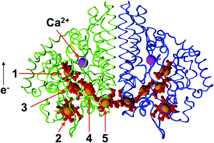 | ||
| Fig. 1 Cartoon model of the NrfA protein dimer of S. deleyianum after the X-ray structure of Einsle et al.20 In the color version, the protein chains are shown as blue and green strands, non-iron heme atoms as red sticks, iron atoms as orange spheres and calcium ions as magenta spheres. The enumeration follows Table 1. | ||
| ID | 1qdb | 1fs7 | C. jejuni |
|---|---|---|---|
| 1 | 474 | 508 | 1001 |
| 2 | 475 | 509 | 1002 |
| 3 | 476 | 510 | 1003 |
| 4 | 477 | 511 | 1004 |
| 5 | 478 | 512 | 1005 |
Charge transfer between a donor and an acceptor—such as the hemes encountered in NrfA—is usually described within the seminal theory of Marcus,22,23 later extended by Hush, Jortner, Dogonadze and Levich, a list by no means exhaustive. In the weak-coupling regime usually applicable for chromophores in proteins, the rate of charge transfer between a donor molecule D and an acceptor molecule A can be estimated as
 | (2) |
Marcus' equation contains three characteristic energies, the thermodynamic driving force ΔG, the reorganization energy λ and the effective electronic donor–acceptor coupling tDA. We aim at computing two of these parameters related to the thermodynamics of the system, λ and ΔG, with the help of molecular dynamics simulations. The effective electronic coupling tDA is estimated using a phenomenological scheme, and the results are integrated into a kinetic theory to access the overall electron dynamics.
The remaining part of this article is organized as follows. The underlying systems and methodology will be introduced in the following section, with a focus on the thermodynamic integration procedure and the analysis of the charge transfer kinetics. In the results section, the free energy landscapes relevant to charge transfer are computed, they form the basis of a description of the electron transfer kinetics. The results are discussed with reference to biochemical findings. Conclusions will be derived in the final section.
2. Model and methods
2.1. Systems
All system geometries are based on X-ray crystallography. The structure of the NrfA protein of S. deleyianum has been solved by Einsle et al. (protein database entry 1QDB20). The unit cell contains a protein dimer and a monomer chain. For W. succinogenes, the corresponding protein has been described by Einsle et al. (PDB entry 1FS7 (ref. 21)), the protein crystallizes as a dimer. The NrfA structure of C. jejuni has been kindly made available by Einsle and Hermann.24,25 Again, the X-ray structure shows a dimerization of the protein.Interheme distances were computed from the X-ray structure coordinates as the minimum interatomic separation of two porphyrin atoms belonging to two different cofactors. Unsurprisingly, the emerging patterns are similar for all three nitrite reductases, they follow a characteristic heme arrangement identified by Einsle and coworkers.16 The distances r13, r23, r34 and r45 are always close to a value chacteristic of π-stacking between aromatic molecules (∼3.4 Å), while r14 varies between 4.8 Å (NrfA from W. succinogenes) and 5.6 Å (NrfA from C. jejuni). Hence, a prospective charge transfer chain 2–3–4–5 appears reasonable, with a branch at heme 3 pointing towards heme 1. Interheme distances between the perimeter hemes in dimers are also particularly small, e.g. a value of 3.9 Å can be observed for the NfrA dimer of S. deleyianum.
2.2. Molecular dynamics
Molecular dynamics simulations have been performed using the pmemd module of the Amber 14 program package.26 As a force field, we used ff10 for the protein, modified heme parameters from Giammona27 and Burggraf and Koslowski,28 and the TIP3P water model. In the work of Giammona, heme containing an Fe2+ ion has been parameterized using the Hartree–Fock procedure to compute the electronic structure and an electrostatic fit of the restrained electrostatic potential type to assign the atomic charges, which we denote as qi,ref. To handle Fe3+, the unusual coordination of the active site heme and those hemes coordinated by lysine, the following procedure has been applied. Electronic properties have been calculated on the density functional theory level using the OLYP exchange–correlation functional and a 6-31G* basis with the help of the Gaussian 09 program suite.29 These calculations have been performed for heme molecules exhibiting an iron +II and a +III oxidation state. For each calculation, an electrostatic potential fit (ESP option) has been performed, leading to charges qi,II and qi,III for each atom i. Special care has been taken to insure that the heme molecules carry the correct integer charge. As charges for the FeII heme, we use those of Giamonna27 which have been determined in a manner consistent with the Amber force field amino acid charges. For the FeIII heme, the charges are given by qi = qi,ref + qi,III − qi,II. The resulting heme charges are given as ESI.† In the parametrization, no reaction field has been used, and no attempt has been made to model the protein environment classically, again consistent with the Amber approach to parameterizing new cofactors. In this way, the resulting charges can be used universally rather than having to be determined specifically for each novel type of environment. Heme bond, angle and dihedral angle parameters have been obtained from the gaff force field. The antechamber tool has been used to generate the parameters for lysine residues that coordinate the heme cofactors.For each of the structures described above, we have isolated one of the monomeric protein chains, added a water box of a 10 Å side length and made the system charge neutral by adding sodium cations. A minimization has been followed by a 500 ps equilibration of the system at a temperature of 298 K and a pressure of 1 bar. Production runs have been performed for 1 ns for each of the proteins. Alternately, a Berendsen thermostat and a rheostat have been used to keep temperature and pressure fluctuations at bay. System sizes typically amount to ∼60![[thin space (1/6-em)]](https://www.rsc.org/images/entities/char_2009.gif) 000 atoms including water and the counterions.
000 atoms including water and the counterions.
2.3. Free energy calculations
In this section, we closely follow Krapf et al.30 in describing the application of thermodynamic integration schemes to charge transfer reactions. Free energy calculations in general, and especially thermodynamic integration calculations, aim at computing the difference in free energy between two states.31,32 In this work, thermodynamic integration has been applied to study the charge transfer in nitrite reductases by considering these states as a charge located on the donor and acceptor heme, respectively.The most important quantity to describe a given state of a system is its standard free energy A0, which can be described by its fundamental connection to a system's configuration integral Z:
 | (3) |
We will later compute Gibbs free energies, G0 instead of Helmholtz free energies A0 as the difference, which is the pressure work pV, is normally negligible when changes in condensed phase systems are studied. Since absolute free energies can only be given with respect to an arbitrary zero, free energy calculations are normally concerned only with computing relative free energies ΔG.
In a thermodynamic integration, the free energy difference between two states A and B is calculated. Additional to the two potential energies VA and VB, a coordinate Λ is used; which couples the educt and product states so that the transition from A to B can be calculated along this non-physical reaction coordinate. A mixed potential V(Λ) results, chosen so that it corresponds to VA for Λ = 0 and VB for Λ = 1:
| V(Λ) = (1 − Λ)VA + ΛVB. | (4) |
In this scheme, the free energy difference between the two states can be described as
 | (5) |
2.4. Charge transfer kinetics
Charge transfer in a chain or network of donor and acceptor molecules can be described by a sequence of chemical reactions, e.g.| hi−hjhkg ⇌ hihj−hkg ⇌ hihjhk−g → hihjhkg−, | (6) |
 | (7) |
![[c with combining right harpoon above (vector)]](https://www.rsc.org/images/entities/i_char_0063_20d1.gif) (t) = (c1(t),c2(t),…,cn(t),g(t))T = (0)exp(−ωt). (t) = (c1(t),c2(t),…,cn(t),g(t))T = (0)exp(−ωt). | (8) |
(K − ω1)(0) = ![[0 with combining right harpoon above (vector)]](https://www.rsc.org/images/entities/char_0030_20d1.gif) , , | (9) |
 | (10) |
(0)μ. The expansion coefficients Aμ have to be selected to meet the initial conditions of the kinetics, leading to a simple system of equations. This approach permits the computations of the concentrations over many orders of magnitude in time without having to perform a tedious numerical integration.
3. Results and discussion
3.1. Thermodynamics
Two characteristic energies entering Marcus' expression of charge transfer rates, the driving force ΔG and the reorganization energy, λ, can be computed with the help of the thermodynamic integration approach, as outlined in Section 2.3. We will now turn to technical details of the analysis of the underlying molecular dynamics simulations and present numerical results.In a charge transfer calculation, the two states A and B are defined as initial and final state of the charge transfer process and the corresponding potentials VA and VB therefore only differ in their charge distributions. The simulated transition from Λ = 0 to Λ = 1 corresponds to moving a charge from A to B.
The computation of ΔG values has been performed in two different ways. Either, a numerical integration is performed, and the integral in eqn (5) is approximated by the trapezoid rule,
 | (11) |
Alternatively, the data points representing ∂V(Λ)/∂Λ can be approximated by a straight line, as appropriate in Marcus' theory for two intersecting parabola with an identical curvature. The integral now becomes
 | (12) |
As an additional benefit of this method, the reorganization energy can be computed directly as λ = a − ΔG = −b/2. As the slope b of ∂V(Λ)/∂Λ is negative, all λ values become positive as expected.
In previous work28 Burggraf and one of us have tested the scheme for a four-heme cytochrome. In that work, we have been able to reproduce the rollercoaster pattern of the free energies (or midpoint potential differences) between the four hemes and their overall spread. More specifically, the computed and experimental midpoint potential differences amount to ΔE12 = −160 mV (exp.: −320 to −390 mV), ΔE23 = 360 mV (exp.: 245 to 310 mV) and ΔE34 = −340 mV (exp.: −345 to −400 mV), the statistical error in the simulations is given by ±80 mV. Furthermore, the outer sphere reorganization energies vanish, a result compatible with a surface accessibility argument given by Bortolotti et al.9
Thermodynamic driving forces, ΔG, have been computed for the four most likely charge transfer reactions, all other ΔG values can be derived using simple thermodynamic cycles. As an additional element of verification, ΔG for the reaction 1→4 has been computed for NrfA from S. deleyianum and C. jejuni. For W. succinogenes, three additional reactions have been investigated. For S. deleyianum, a sample analysis is presented in Fig. 2. The calculated driving forces are presented in Table 2, both for the trapezoid rule and the linear regression analysis. In all three organisms, the site free energies computed from the driving forces can be grouped into a high and a low free energy fraction. For NrfA from S. deleyianum, the active and the interfacial heme form thermodynamic basins of attraction, with free energies that are 13 to 15 kcal mol−1 lower than those of the other cofactors. For NrfA from C. jejuni, the entry and the interfacial heme are energetically favoured by 11 to 16 kcal mol−1. For NrfA from W. succinogenes, we observe a single high-energy state, the active site heme cofactor, which is preferred to the other hemes by 8 to 11 kcal mol−1. Although the free energy landscape looks different for each organism, two features are common to all of them. First, storage of an even number of electrons is thermodynamically favoured. For NrfA from S. deleyianum and C. jejuni, two electrons can be stored in low-energy hemes, whereas W. succinogenes NrfA can accommodate four electrons per monomer. Second, the interfacial heme 5 shows a particularly low ΔG value, it is likely to be populated by an electron at thermodynamic equilibrium. Hence, it shows the potential of acting as a site participating in frequent intermonomer charge transfer. We will return to this issue once the charge transfer kinetics is discussed. The energetics described in this section is also presented schemetically in Fig. 3.
 | ||
| Fig. 2 Thermodynamic integration analysis for charge transfer in NrfA from C. jejuni. The symbols refer to the reactions 2→3 (●), 1→3 (○) and 4→5 (×). The straight lines represent a least squares linear fit. For details, see Section 3.1. | ||
| Organism | Reaction | ΔG(R) | λ(R) | ΔG(I) | λ(H) |
|---|---|---|---|---|---|
| S. deleyianum | 1→3 | 13 ± 6 | 25 ± 3 | 13 | 25 |
| 1→4 | 6 ± 4 | 36 ± 2 | 6 | 38 | |
| 2→3 | 9 ± 4 | 33 ± 2 | 9 | 31 | |
| 3→4 | −7 ± 4 | 25 ± 2 | −7 | 26 | |
| 4→5 | −7 ± 2 | 30 ± 2 | −7 | 32 | |
| C. jejuni | 1→3 | 2 ± 3 | 27 ± 1 | 2 | 28 |
| 1→4 | −3 ± 3 | 37 ± 2 | −3 | 40 | |
| 2→3 | 14 ± 3 | 33 ± 1 | 14 | 35 | |
| 3→4 | −2 ± 4 | 29 ± 2 | −2 | 30 | |
| 4→5 | −14 ± 4 | 31 ± 2 | −13 | 31 | |
| W. succinogenes | 1→3 | −9 ± 3 | 29 ± 1 | −9 | 29 |
| 2→3 | 1 ± 3 | 36 ± 2 | 1 | 33 | |
| 3→4 | −1 ± 3 | 28 ± 1 | −1 | 27 | |
| 4→5 | 0 ± 3 | 30 ± 2 | 1 | 32 | |
| 2→1 | 12 ± 1 | 44 ± 1 | 12 | 43 | |
| 2→3 | 2 ± 3 | 38 ± 1 | 2 | 37 | |
| 2→4 | −2 ± 2 | 44 ± 1 | −2 | 45 | |
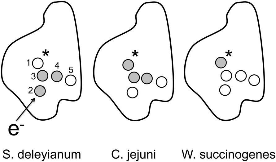 | ||
| Fig. 3 Cartoon representation of the energetics of the heme cofactors in NrfA of three organisms. White circles represent hemes that show a low free energy and that act as preferential sites of electron storage. Grey circles depict high-energy hemes. The asterisk marks the active site, an arrow the flow of charge into the system. The enumeration follows Table 1. | ||
To study the influence of long-range electron–electron interactions, we have computed reaction free energies for (i) the transport of one excess electron (i.e. one Fe2+ heme and four Fe3+ hemes) and (ii) a single hole transferred in a system carrying four excess charges. In the absence of long-range correlations, the corresponding reaction free energies should only differ in sign. Within the statistical errors of our calculations, this relation is fulfilled, as evident from Fig. 4. In the absence of correlation effects, the thermodynamic potentials can be compared to electrochemical midpoint potentials. To our knowledge, these quantities are not available for the NrfA proteins studied here. For proteobacteria—such as the organisms under review here—midpoint potentials are spread over a range from 259–297 mV (E. coli, S. oneidensis, D. vulgaris) over 470 mV (T. nitratireducens) to 630 mV (D. desulfuricans).10 This compares well to the 8 kcal mol−1 (=350 meV) to 16 kcal mol−1 (=700 meV) scale observed here.
 | ||
| Fig. 4 Hole vs. electron free energy differences for charge transfer reactions between hemes in the NrfA protein of S. deleyianum. The electron reaction free energies are also listed in Table 2. The straight line represents ideal particle–hole symmetry. | ||
Typical statistical errors in the reaction ΔG values amount to 1–3 kcal mol−1 for the linear regression analysis, they increase slightly for the trapezoid rule integration. Both methods differ by 1 kcal mol−1 or less. Systematic errors are more difficult to access. The lack of polarization degrees of freedom inherent to the force fields used here is likely to play a role. For simple model systems, characteristic charge transfer energies seem to be reduced upon the introduction of polarizable force fields,33 although effects of the order 22% reported in that study are not dramatic once biological systems are concerned. A more serious problem arises from the reduction of the protein complex structure (consisting of NrfH and a NrfA dimer) to a single monomer. Heme cofactors close to protein interfaces may now become exposed to water and thus experience a model environment considerably more polarizable than within the complex. From a mean-field perspective of dielectrics, this increases the 1 − ε−1 prefactor characteristic of classical reaction field approaches, e.g. of the Onsager type. In our computations, the entry and the interface hemes, 2 and 5, may be affected most and show ΔG values that are too low.
The reorganization energies, λ, lie within a comparatively narrow range of 25–36 kcal mol−1 for the linear regression analysis. Statistical errors are even smaller than those computed for the driving forces, they amount to 1–2 kcal mol−1. Whereas ΔG is a well-defined thermodynamic state function, dynamic effects have an influence on the magnitude of λ, which is usually overestimated in a straightforward application of the TI scheme. For the outer sphere reorganization energy of a donor–acceptor charge transfer within a simple model of two hard spheres of diameter σ and separation R dispersed in a polarizable dielectric medium, Marcus has given the expression
 | (13) |
3.2. Kinetics
We now turn to the kinetic analysis involving a system of five hemes and an electron trap coupled to the active site. Interheme charge transfer rates are computed using Marcus' expression for nonadiabatic charge transfer, eqn (2). Two of the characteristic energies, the driving force ΔG and the reorganization energy λ have been calculated using the thermodynamic integration scheme, as detailed in the preceding section. The total rate including the distance-dependence electronic coupling, i.e. tDA, has been estimated using the empirical Dutton–Moser rule,34,35| log10kDA(rij) = 15 − αrij − 3.1(ΔG + λ)2/λ | (14) |
The thus computed interheme charge transfer rates enter a kinetic scheme, as described in Section 2.4. Results of the semi-analytical integration of the kinetic eqn (10) are presented in Fig. 5 and 6 with different initial conditions. In Fig. 5, only the entry heme 2 is initially occupied. This implies that an electron has just been passed from NrfH to NrfA, while an electron acceptor is present at the active site. For NrfA from S. deleyianum and W. succinogenes, the entry site is rapidly depopulated, while the electron acceptor carries half of its maximum charge on a time scale of ∼10−7 s. Taking into account that six electrons are required to produce one ammonia cation, this time scale is considerably faster and thus compatible with turnover data from Clarke et al.,39 which amount to 962 s−1 for NrfA from S. deleyianum. A time scale of 10−3 s required to transfer an electron to the acceptor—as encountered for NrfA from C. jejuni—seems, however, to be slightly too slow. This effect may be attributed to the ‘sticky’ sites 2 and 5, which show a particularly low ΔG. As discussed above, solvent polarization effects may lead to an underestimate of the free energies on these sites, thus reducing the charge transfer rate considerably, while other types of free energy landscape are less sensitive to this effect.
 | ||
| Fig. 5 NrfA heme and trap populations as a function of the decadic logarithm of time for (a) S. deleyianum, (b) C. jejuni (b) and (c) W. succinogenes. Solid line: entry site heme population, dotted line: trap population, dashed line: sum of all reaction intermediates. Initially, the entry heme cofactor 2 is populated. | ||
 | ||
| Fig. 6 NrfA heme and trap populations as a function of the decadic logarithm of time for (a) S. deleyianum, (b) C. jejuni and (c) W. succinogenes. Solid line: interfacial heme population, dotted line: trap population, dashed line: sum of all reaction intermediates. Initially, the interfacial heme cofactor 5 is populated. | ||
On a time scale comparable with the charge transfer process from the entry site to the final acceptor, other hemes can be populated. The sum of these populations is shown as a dashed line in Fig. 5. Whereas the charge transfer chain can readily transfer an electron to the active site (conducting mode) it is able to redistribute and store an electron on the same time scale once the acceptor is absent (storage mode).
In Fig. 6, we present the kinetics with the interfacial heme 5 populated initially. Here, we have a situation where an electron had been transferred to NrfA in the absence of a substrate, giving it sufficient time to localize on one of the storage sites. At this stage, the trap is now coupled to the system. We find similar time scales as above, with reaction intermediates essentially missing for NrfA from S. deleyianum and C. jejuni. This is not surprising, as the heme 5 initially populated here usually constitutes one of the dominant intermediates in the conducting mode. For NrfA from W. succinogenes, the decharging pattern is almost indistinguishable from that of the conducting mode. Here, the electron is shuffled within a pool of four storage sites prior to a transfer to the trap.
To simplify the remaining part of the kinetic analysis, we define a characteristic time τi at which the trap population equals one half, starting from a given low-energy or entry heme i. To make sure that the irreversible trapping reaction is not the rate-limiting step, the rate populating the trap is arbitrarily set to a value exceeding all other rates, here k1g = 1.0 × 10¹³ s−1 is used. For NrfA from W. succinogenes, the hemes 2–5 form basins of electron attraction, and we find τi = 1.6 × 10⁻⁷ s for all of them. Regardless of their initial center of localization, all electrons have to pass the kinetic bottleneck 3→1. A similar phenomenon can be observed for charge transfer through the C. jejuni nitrite reductase with preferential sites 2 and 5 as centers of electron attraction. Here, τ2 = τ5 = 1.3 × 10⁻⁴ s is observed. For NrfA from S. deleyianum, the low-energy heme 1 doubles as the exit site, so τ1 depends on k1g. Here, we find τ5 = 6.3 × 10⁻⁸ s for the site exhibiting the lowest ΔG value. Switching on the trapping path, this site is exactly as swiftly depopulated as the entry site, and we have τ2 = τ5. For NrfA from S. deleyianum, we have also inspected the kinetics of heme 1 being depopulated with the initial charge residing on one of the hemes of its counterpart within a nitrite reductase dimer. Characteristic time scales 2.5 × 10⁻⁷ s (initial localization on the interfacial heme) and 4.0 × 10⁻⁷ s (initial localization on the active site) are close to each other and slightly larger than those observed for charge transfer within a monomer. On-site Coulomb blockade effects have not been considered in our analysis, they become important once a heme population approaches unity.
4. Conclusions
In this work, we applied thermodynamic integration computations to analyze charge transfer processes in the pentaheme NrfA protein of three anaerobic bacteria from a theoretical and computational perspective. The calculated thermodynamic driving forces can be grouped into high-energy hemes and an even number of low-energy cofactors. In this manner, the entire NrfA enzyme stores electrons as multiples of two with each charge residing on a different heme. The actual number of electrons stored and the free energy landscape of charge transfer may differ from organism to organsim, and hemes may double as storage and entry or active sites. Regardless of the organism, a heme located at the interface of the NrfA dimer always exhibits the lowest ΔG, a fact already suggesting that charge transfer between the monomers may play an important role. Reorganization energies are notably uniform, they are rescaled by an argument based on dielectric continuum theory. The scaled reorganization energies are larger than those reported for experiments heme-based systems in the literature.9 As we see this effect not only for the NrfA proteins, but also for different systems containing hemes or other centers of charge localization, we suspect that this systematic overestimate may be an artefact of the Amber force field. The overall depopulation kinetics of NrfA from S. deleyianum and W. succinogenes are compatible with experimental turnover numbers, whereas C. jejuni NrfA rates are considerably slower. This exceptional behaviour can be traced back to an underestimate of the free energies of the entry and the interfacial heme cofactor, which in turn slows down charge transfer processes involving these sites as a donor. Other arrangements of storage sites much less sensitive to this problem. It can only be overcome by simulating the entire NrfA dimer plus NrfHA complex, a task currently out of reach of our computational capabilities. Concerning the complexity of the system and the polarization issues discussed above, the dielectric continuum approach of Ullmann and coworkers40 may still provide an interesting alternative to full atomistic simulations.While only a single excess electron can populate each heme, the kinetic analysis suggests that electrons are not only stored in pairs, but that two electrons can also be released almost simultaneously from the enzyme towards the active site, hence avoiding the production of reactive oxidizing species as reaction intermediates. These are findings are compatible with the two-electron nature of the reduction process at the active site of NfrA from E. coli, as observed by Angove et al.,41 but at variance with the observations of Judd et al. made for NrfA from S. oneidensis,42 who found a one-electron character. Fast charge transfer across the boundary of a monomer is possible via a pair of interfacial hemes not only from a thermodynamic, but also from a kinetic perspective. This picture of a functional dimer is in accord with the interpretation of the protein structure by Einsle and coworkers.20,21
From our point of view, the NrfA heme cofactors show a remarkable versatility: they can act as an initial electron acceptor, active site, electron storage site and participate as conducting elements in a charge transfer chain, often doubling in function. This behaviour is in notable contrast to the findings of Breuer et al.,43 who studied charge transfer phenomena in the MtrF decaheme protein of Shewanella oneidensis using a combination of molecular dynamics and density functional theory. These authors conclude that driving forces and electronic couplings in this enzyme are tuned to enable a maximum transport rate, with each heme solely acting as a stepping stone in a complex charge transfer chain. These views on multiheme proteins are, however, not mutually exclusive. MtrF is part of a long-range electron transport chain of six proteins with the main task of transferring electrons over long distances as efficiently as possible. NrfA, on the other hand, has to store and deliver six electrons over a comparatively small distance, and one of its cofactors also doubles as the active site.44 Combined, these findings add to the current perspective on multi-heme proteins as versatile tools suited to a multitude of biochemical tasks.45
Acknowledgements
We thank F. Burggraf and T. Steinbrecher for their help and assistance with the Amber program in the initial stage of this work. Fruitful discussions with O. Einsle, D. Gnandt and B. Hermann are gratefully acknowledged. We are particularly indebted to O. Einsle and B. Hermann for making their X-ray analysis of C. jejuni NrfA available.References
- O. Einsle and P. M. H. Kroneck, Structural basis of denitrification, Biol. Chem., 2004, 385, 875–883 CrossRef CAS PubMed.
- J. A. Brandes, N. Z. Boctor, G. D. Cody, B. A. Cooper, R. M. Hazen and H. S. Jr. Yoder, Abiotic nitrogen reduction on the early Earth, Nature, 1998, 395, 365–367 CrossRef CAS PubMed.
- G. Wächterhäuser, On the chemistry and evolution of the pioneer organism, Chem. Biodiversity, 2007, 4, 584–602 Search PubMed.
- Y. L. Yung and M. B. McElroy, Fixation of nitrogen in the prebiotic atmosphere, Science, 1979, 203, 1002–1004 CAS.
- R. L. Mancinelli and C. P. McKay, The evolution of nitrogen cycling, Origins Life Evol. Biospheres, 1988, 18, 311–325 CrossRef CAS.
- J. F. Kasting, Earths early atmosphere, Science, 1993, 259, 920–926 CrossRef CAS PubMed.
- R. Navarro-González, C. P. McKay and D. N. Mvondo, A possible nitrogen crisis for Archaeanlife due to reduced nitrogen fixation by lightning, Nature, 2001, 412, 61–64 CrossRef PubMed.
- J. E. T. McLain and D. A. Martens, Nitrous oxide flux from soil amino acid mineralization, Soil Biol. Biochem., 2005, 37, 289–299 CrossRef CAS.
- C. A. Bortolotti, M. E. Siwko, E. Castellini, A. Ranieri, M. Sola and S. Corni, The reorganization energy in cytochrome c is controlled by the accessibility of the heme to the solvent, J. Phys. Chem. Lett., 2011, 2, 1761–1765 CrossRef CAS.
- R.-M. A. S. Doyle, S. J. Marritt, F. D. Gwyer, T. G. Lowe, T. V. Tikhonova, V. O. Popov, M. R. Cheesman and J. N. Butt, Contrasting catalytic profiles of multiheme nitrite reductases containing CxxCK heme-binding motifs, JBIC, J. Biol. Inorg. Chem., 2013, 18, 655–667 CrossRef CAS PubMed and references therein.
- D. Bykov and F. Neese, Substrate binding and activation in the active site of cytochrome c nitrite reductase. A density functional study, JBIC, J. Biol. Inorg. Chem., 2011, 16, 417–430 CrossRef CAS PubMed.
- D. Bykov, M. Plog and F. Neese, Heme-bound nitroxyl, hydroxylamine, and ammonia ligands as intermediates in the reaction cycle of cytochrome c nitrite reductase: a theoretical study, JBIC, J. Biol. Inorg. Chem., 2014, 19, 97–112 CrossRef CAS PubMed.
- B. C. Berks, S. J. Ferguson, J. W. B. Moir and D. J. Richardson, Enzymes and associated electron transport systems that catalyse the respiratory reduction of nitrogen oxides and oxyanions, Biochim. Biophys. Acta, 1995, 1232, 97–173 CrossRef.
- D. J. Richardson, J. M. Wehrfritz, A. Keech, L. C. Crossman, M. D. Roldan, H. J. Sears, C. S. Butler, A. Reilly, J. W. Moir, B. C. Berks, S. J. Ferguson, A. J. Thompson and S. Spiro, The diversity of redox proteins involved in bacterial heterotrophic nitrification and aerobic denitrification, Biochem. Soc. Trans., 1998, 26, 401–408 CrossRef CAS PubMed.
- J. Simon, Enzymology and bioenergetics of respiratory nitrite ammonification, FEMS Microbiol. Rev., 2002, 26, 285–309 CrossRef CAS PubMed.
- O. Einsle, Structure and function of formate-dependent cytochrome c nitrite reductase, NrfA, Methods Enzymol., 2011, 496, 399–422 CAS.
- J. Simon, R. Gross, O. Einsle, P. M. H. Kroneck, A. Kroeger and O. Klimmek, A NapC/NirT-type cytochrome c (NrfH) is the mediator between the quinone pool and the cytochrome c nitrite reductase of Wolinella succinogenes, Mol. Microbiol., 2000, 35, 686–696 CrossRef CAS PubMed.
- J. Simon, R. Pisa, T. Stein, R. Eichler, O. Klimmek and R. Gross, The tetraheme cytochrome c NrfH is required to anchor the cytochrome c nitrite reductase (NrfA) in the membrane of Wolinella succinogenes, Eur. J. Biochem., 2001, 268, 5776–5782 CrossRef CAS PubMed.
- O. Einsle, Structure and function of cytochrome c nitrite reductase, Dr. rer. nat. thesis, University of Konstanz, 1999, p. 101 Search PubMed.
- O. Einsle, A. Messerschmidt, P. Stach, G. P. Bourenkov, H. D. Bartunik, R. Huber and P. M. H. Kroneck, Structure of cytochrome c nitrite reductase, Nature, 1999, 400, 476–480 CrossRef CAS PubMed.
- O. Einsle, P. Stach, A. Messerschmidt, J. Simon, A. Kröger, R. Huber and P. M. H. Kroneck, Cytochrome c nitrite reductase from Wolinella succinogenes-Structure at 1.6 angstrom resolution, inhibitor binding, and heme-packing motifs, J. Biol. Chem., 2000, 275, 39608–39616 CrossRef CAS PubMed.
- R. A. Marcus, On the theory of oxidation-reduction reactions involving electron transfer, J. Chem. Phys., 1956, 24, 966–978 CrossRef CAS.
- R. A. Marcus, Chemical and electrochemical electron transfer, Annu. Rev. Phys. Chem., 1964, 15, 155–196 CrossRef CAS.
- B. Hermann and O. Einsle, private communication, 2013.
- B. Herrmann, Crystallographic characterization of multiheme enzymes: cytochrome c nitrite reductase from Campylobacter jejuni and octaheme sulfite reductase from Wolinella succinogenes, Dr. rer. nat. thesis, University of Freiburg, 2014 Search PubMed.
- D. A. Case, V. Babin, J. T. Berryman, R. M. Betz, Q. Cai, D. S. Cerutti, T. E. Cheatham, III, T. A. Darden, R. E. Duke, H. Gohlke, A. W. Goetz, S. Gusarov, N. Homeyer, P. Janowski, J. Kaus, I. Kolossvry, A. Kovalenko, T. S. Lee, S. LeGrand, T. Luchko, R. Luo, B. Madej, K. M. Merz, F. Paesani, D. R. Roe, A. Roitberg, C. Sagui, R. Salomon-Ferrer, G. Seabra, C. L. Simmerling, W. Smith, J. Swails, R. C. Walker, J. Wang, R. M. Wolf, X. Wu and P. A. Kollman, AMBER 14, University of California, San Francisco, 2014 Search PubMed.
- D. A. Giammona, An examination of conformational flexibility in porphyrins and bulky-ligand binding in myoglobin, PhD thesis, University of California, Davis, 1984 Search PubMed.
- F. Burggraf and T. Koslowski, Charge transfer through a cytochrome multiheme chain: Theory and simulation, Biochim. Biophys. Acta, 2014, 1837, 186–192 CrossRef CAS PubMed.
- M. J. Frisch, G. W. Trucks, H. B. Schlegel, G. E. Scuseria, M. A. Robb, J. R. Cheeseman, G. Scalmani, V. Barone, B. Mennucci, G. A. Petersson, H. Nakatsuji, M. Caricato, X. Li, H. P. Hratchian, A. F. Izmaylov, J. Bloino, G. Zheng, J. L. Sonnenberg, M. Hada, M. Ehara, K. Toyota, R. Fukuda, J. Hasegawa, M. Ishida, T. Nakajima, Y. Honda, O. Kitao, H. Nakai, T. Vreven, J. A. Montgomery, Jr., J. E. Peralta, F. Ogliaro, M. Bearpark, J. J. Heyd, E. Brothers, K. N. Kudin, V. N. Staroverov, T. Keith, R. Kobayashi, J. Normand, K. Raghavachari, A. Rendell, J. C. Burant, S. S. Iyengar, J. Tomasi, M. Cossi, N. Rega, J. M. Millam, M. Klene, J. E. Knox, J. B. Cross, V. Bakken, C. Adamo, J. Jaramillo, R. Gomperts, R. E. Stratmann, O. Yazyev, A. J. Austin, R. Cammi, C. Pomelli, J. W. Ochterski, R. L. Martin, K. Morokuma, V. G. Zakrzewski, G. A. Voth, P. Salvador, J. J. Dannenberg, S. Dapprich, A. D. Daniels, O. Farkas, J. B. Foresman, J. V. Ortiz, J. Cioslowski and D. J. Fox, Gaussian 09, Revision B.01, Gaussian, Inc., Wallingford CT, 2010 Search PubMed.
- S. Krapf, T. Koslowski and T. Steinbrecher, The thermodynamics of charge transfer in DNA photolyase: using thermodynamic integration calculations to analyse the kinetics of electron transfer reactions, Phys. Chem. Chem. Phys., 2010, 12, 9516–9525 RSC.
- J. Kirkwood, Statistical mechanics of fluid mixtures, J. Chem. Phys., 1935, 3, 300–313 CrossRef CAS.
- T. Steinbrecher and A. Labahn, Towards accurate free energy calculations in ligand-proteinbinding studies, Curr. Med. Chem., 2010, 17, 767–785 CrossRef CAS PubMed.
- J. Blumberger and G. Lamoureux, Reorganization free energies and quantum corrections for a model electron self-exchange reaction: comparison of polarizable and non-polarizable solvent models, Mol. Phys., 2008, 106, 1597–1611 CrossRef CAS.
- C. C. Moser, J. M. Keske, K. Warncke, R. S. Farid and P. L. Dutton, Nature of biological electron transfer, Nature, 1992, 355, 796–802 CrossRef CAS PubMed.
- C. C. Page, C. C. Moser, X. Chen and P. L. Dutton, Natural engineering principles of electron tunnelling in biological oxidation–reduction, Nature, 1999, 402, 47–52 CrossRef CAS PubMed.
- S. Krapf, S. Weber and T. Koslowski, The road not taken: a theoretical view of an unexpected cryptochrome electron transfer path, Phys. Chem. Chem. Phys., 2012, 14, 11518 RSC.
- D. N. LeBard and D. V. Matyushov, Proteinwater electrostatics and principles of bioenergetics, Phys. Chem. Chem. Phys., 2010, 12, 15335–15348 RSC.
- D. V. Matyushov, Protein electron transfer: dynamics and statistics, J. Chem. Phys., 2013, 139, 02512 CrossRef PubMed.
- T. A. Clarke, A. M. Hennings, B. Burlat, J. N. Butt, J. A. Cole and D. J. Richardson, Respiratory nitrate and nitrite pathway in the denitrifier haloarchaeon Haloferax mediterranei, Biochem. Soc. Trans., 2006, 34(part 1), 143–145 CrossRef CAS PubMed.
- E. Bombarda and G. M. Ullmann, Continuum electrostatic investigations of charge transfer processes in biological molecules using a microstate description, Faraday Discuss., 2011, 148, 173–179 RSC.
- H. C. Angove, J. A. Cole, D. J. Richardson and J. N. Butt, Protein film voltammetry reveals distinctive fingerprints of nitrite and hydroxylamine reduction by a cytochrome c nitrite reductase, J. Biol. Chem., 2002, 277, 23374–23381 CrossRef CAS PubMed.
- E. T. Judd, M. Youngblut, A. A. Pacheco and S. J. Elliott, Direct electrochemistry of Shewanella oneidensis cytochrome c nitrite reductase: evidence of interactions across the dimeric interface, Biochemistry, 2012, 51, 10175–10185 CrossRef CAS PubMed.
- M. Breuer, K. M. Rosso and J. Blumberger, Electron flow in multiheme bacterial cytochromes is a balancing act between heme electronic interaction and redox potentials, Proc. Natl. Acad. Sci. U. S. A., 2014, 111(2), 611–616 CrossRef CAS PubMed.
- O. Einsle, A. Messerschmidt, R. Huber, P. M. H. Kroneck and F. Neese, Mechanism of the six-electron reduction of nitrite to ammonia by cytochrome c nitrite reductase, J. Am. Chem. Soc., 2002, 124, 11737–11745 CrossRef CAS PubMed.
- K. D. Bewley, K. E. Ellis, M. A. Firer-Sherwood and S. J. Elliott, Multi-heme proteins: Nature's electronic multi-purpose tool, Biochim. Biophys. Acta, 2013, 1827, 938–948 CrossRef CAS PubMed.
Footnote |
| † Electronic supplementary information (ESI) available. See DOI: 10.1039/c4cp04383a |
| This journal is © the Owner Societies 2015 |