 Open Access Article
Creative Commons Attribution 3.0 Unported Licence
Manufacture of dense CAU-10-H coatings for application in adsorption driven heat pumps: optimization and characterization†
M. F.
de Lange
*ab,
T.
Zeng
ac,
T. J. H.
Vlugt
b,
J.
Gascon
a and
F.
Kapteijn
*a
aCatalysis Engineering, Chemical Engineering Department, Delft University of Technology, Julianalaan 136, 2628 BL Delft, The Netherlands. E-mail: m.f.delange@tudelft.nl, f.kapteijn@tudelft.nl
bEngineering Thermodynamics, Process & Energy Laboratory, Delft University of Technology, Leeghwaterstraat 39, 2628 CB Delft, The Netherlands
cDepartment Thermo-chemical Conversion, Deutsches Biomasse-forschungszentrum gemeinnützige GmbH, Torgauer Straße 116, 04347 Leipzig, Germany
First published on 12th May 2015
Abstract
CAU-10-H displays a highly suitable step-wise water adsorption behaviour for application in adsorption driven heat pumps and chillers. For actual application, manufacturing of coatings of this material on thermally conductive surfaces is highly desired. Direct, single-step, crystallization of CAU-10-H on either metallic or anodized aluminium yields a significant amount of by-product(s) and an inhomogeneous substrate coverage. Although adequate pretreatment of the substrates before crystallization improves the quality of obtained coatings, significant improvements are achieved only when crystal nucleation and growth are separated. More specifically, application of a reactive seeding approach with anodized aluminium leads to full coverage of the substrate surface, high MOF loading and high purity of the crystalline phase, homogeneous layer thickness, narrow crystal size distribution, and good stability in repeated water adsorption–desorption cycles.
Introduction
Adsorption driven heat pumps and chillers, AHP/ADC's, have great potential for reducing primary energy consumption and mitigating associated CO2 emissions and anthropogenic climate change.1 Devices based on this principle can potentially employ low grade thermal energy, e.g. solar or industrial waste heat, to sustainably supply cooling and heating, making use of the reversible ad- and desorption of, preferably, water. Compared to commercially applied adsorbents, the Metal–Organic Framework (MOF) CAU-10-H shows a higher volumetric adsorption capacity and thermodynamic efficiency for water as a working fluid.1,2 CAU-10-H contains isophthalic acid as organic linker and cis-connected AlO6-polyhedra, forming helical chains. The resulting structure has unidirectional pores. This MOF consists of abundantly available aluminium and isophthalic acid, both of which are produced industrially on a large scale,3 placing this MOF among the most commercially viable ones. Furthermore, its synthesis does not require an expensive sacrificial template, in contrast to e.g. the zeotype structures of the AQSOA-series4–6 used in commercially available devices of Mitsubishi.7–13 The potential of CAU-10-H is further strengthened by the fact that the material is perfectly stable towards water and has not shown any sign of degradation over 700 repeated adsorption/desorption cycles,14 a feature not commonly encountered for MOFs when exposed to water.1 Altogether, these features confirm CAU-10-H as a commercially viable adsorbent for application in adsorption driven heat pumps and chillers. For successful implementation however, heat and mass transport should be fast enough to allow for high volume-specific power output. A promising way to achieve this is by coating a thermally conductive surface with the adsorbent of choice. E.g., the AQSOA-series are coated on a heat exchanger by using a binder.6,7 Furthermore, as mentioned by Ferey et al., MOFs show improved efficiency for air dehumidification, an application that shows similarities with AHP/ADC's, compared to zeolitic materials, when they are coated on honeycomb shaped rotors.15 To create such a coating, ideally, a binderless method is preferred as the binder does not only add to the cost of a device, but also dilutes the active material, decreasing the overall efficiency of the system. When MOFs are considered specifically, (organic) binders cannot be removed by combustion after coating, as this would also cause oxidation of the ligand of the MOF. Therefore, a coating by directly crystallizing the MOF on a thermally conductive surface is preferred.16 Previous results already indicated that CAU-10-H coatings can be formed directly on metallic aluminium (m-Al) supports.17 By addition of HCl to the reaction mixture, a higher surface loading was achieved, but an incomplete surface coverage and a broad range of crystal sizes were observed. Furthermore, HCl addition induced the formation of unidentified by-product(s).17 The aim of this study is to optimize the properties of the formed crystalline layer of CAU-10-H on aluminium substrates. Desired properties for this layer are: (i) full coverage of the surface, (ii) high MOF loading, (iii) homogeneous layer thickness, (iv) narrow crystal size distribution, (v) sufficient stability under working conditions and (vi) high purity of the crystalline phase. Here results of a systematic study of different synthesis parameters and an optimized protocol for the synthesis of homogeneous CAU-10-H coatings are presented.Experimental
Materials
Two different types of substrates were applied. Metallic aluminium (m-Al) substrates with a thickness of 0.5 mm and a purity of 99.9999% were purchased from Mateck GmbH. Anodized aluminium (a-Al) substrates (Durapor 15) with a thickness of 0.5 mm were purchased from Polychromal B.V. According to the manufacturer's specification, the aluminium oxide layer is 15 μm thick. For all syntheses, substrates were cut into squares of 20 × 20 mm with corners cut-off. Typically, the sample mass was ~0.54 g and ~0.58 g for metallic and anodized aluminium substrates, respectively. The substrates were used either as received or after specified pretreatment. Isophthalic acid, 1,3-H2BDC (99%), aluminium sulfate octadecahydrate, Al2(SO4)3·18H2O (ACS reagent ≥ 99.8%), N,N-dimethylformamide for synthesis, DMF (anhydrous 99.8%), N,N-dimethylformamide for post-processing, DMF (puriss p.a., ACS reagent ≥ 99.8%), hydrochloric acid, HCl (ACS reagent, 37% in water), acetone (ACS reagent, ≥ 99.5%) and methanol (anhydrous 99.8%) were purchased from Sigma-Aldrich and used without further purification. Deionized water with a conductivity of 0.12 μS cm−1 was prepared using a MILIPORE MILI-Q.Powder synthesis CAU-10-H
CAU-10-H powder was synthesized using two different ways, by conventional heating and microwave irradiation. The main difference in synthesis protocols lies in the employed reaction time, which is generally significantly shorter when microwave irradiation is used.18–20 The molar ratios of reactants are identical in both approaches, as is the sample post-processing.Formation of CAU-10-H on substrates
Three synthesis protocols have been followed in order to optimize the formation of CAU-10-H on aluminium substrates: (i) the single-step direct synthesis, adopted from previous work,17 and two multi-step procedures in order to separate crystal nucleation and growth, (ii) reactive21 and (iii) thermal seeding.22 All substrates and possible solids obtained in the reaction solution (i.e. filtration residue) were activated following an identical protocol.For the reactive seeding step, pretreated substrates were placed in a Teflon insert with a capacity of 45.0 ml. Subsequently, 1,3-H2BDC (5.2 mmol, 0.86 g), DMF (4.2 ml), HCl (37% in water, 1.7 ml) and deionized water (17.0 ml) were added. For a-Al, no HCl was added and the amount of deionized water was adjusted to keep the total amount of water constant. The Teflon insert was closed with a lid, sealed in an autoclave, and heated in a convection oven (Heraeus T6, 5 °C min−1) to the required reaction temperature (135 °C). Stirring was not applied during synthesis. The time allowed for reactive seeding, trs was varied from 1 to 4 h. After reaction, the autoclave was removed from the oven and allowed to cool to ambient temperature. The seeded substrate was thoroughly rinsed with DMF and deionized water and subsequently dried in an oven (Heraeus, T5042) at 100 °C for 1 h. This seeded substrate was weighed and stored in a sample vial, until used in the second step.
For secondary growth, the seeded substrates were placed once more in a Teflon insert with a capacity of 45.0 ml. Either of two different precursor solutions, without added acidity, were used keeping volume of water constant, employing a dilution ratio (DR) of either 2 or 5 for the other reactants, relative to conventional synthesis. E.g. for a dilution ratio of 2, the following was added: 1,3-H2BDC (2.6 mmol, 0.43 g), Al2(SO4)3·18H2O (2.6 mmol, 1.7 g), DMF (2.2 ml), deionized water (17.0 ml). For a ratio of 5, this becomes: 1,3-H2BDC (1.0 mmol, 0.17 g), Al2(SO4)3·18H2O (1.0 mmol, 0.69 g), DMF (0.84 ml, 0.80 g), deionized water (17.0 ml). The Teflon insert was closed with a lid, sealed in an autoclave, and heated in a convection oven (Heraeus T6, 5 °C min−1) to the required reaction temperature (135 °C). After a reaction time of 12 h, the autoclave was removed from the oven and allowed to cool to ambient temperature. The reaction mixture with the substrate was post-processed as described previously.
The used seeds are created with microwave heating. Three different seed solutions are employed. Solution 1 is the reaction mixture, after cooling down and without further treatment (for a yield of ~65%, as commonly observed for conventional synthesis,2 this would be roughly 3 wt.% CAU-10-H). For the other solutions, CAU-10-H powder was processed after synthesis as before. Seed solutions 2 and 3 contain CAU-10-H seeds dispersed in deionized water, respectively with 2.5 and 5 wt.% MOF. Prior to the seeding experiments, the selected seed solution was sonicated in an ultrasonic bath (VGT-1730QT, 100 W, 40 kHz) for 1 min to break down agglomerates.
For the attachment of seeds, pretreated substrates were placed in a petri dish and heated in a convection oven (Heraeus T6, 5 °C min−1) at 200 °C for 15 min. While the substrates were still inside the oven, a seed solution was dropped on the surface of the hot substrates using a pipette until the surface was completely covered with the solution (2–6 ml, roughly). The substrates were kept inside the oven for 15 min to allow for complete evaporation of the solvent. To obtain a complete coverage of the substrate surface with seed crystals, this procedure had to be repeated two more times when seed solution 1 was used. In contrast, only one thermal seeding step was required when either solution 2 or 3, only containing CAU-10-H seeds in water, was used. The seeded substrates were then rinsed with deionized water, to remove excess material and not attached seeds, and subsequently dried in an oven (Heraeus T5042) at 100 °C for 1 h. The secondary growth step is the same for thermal and reactive seeding (vide supra).
All methods and procedures for characterization of powder samples and substrates can be found in detail in section S2.†
Results and discussion
The results of bulk (powder) synthesis of CAU-10-H are discussed as reference in comparison with CAU-10-H coated on substrates. The crystals formed are used as seeds in the thermal seeding approach. Subsequently, coatings obtained by direct synthesis are discussed briefly. The main focus of this article, the benefits of employing two multi-step approaches, reactive and thermal seeding are discussed next. Finally, selected substrates are characterized and compared in detail.Powder synthesis
From both conventional and microwave synthesis, pure CAU-10-H is obtained (Fig. S1, S2†). The adsorption capacity of N2 and H2O is seemingly somewhat larger for the material obtained by microwave synthesis (Fig. S3†). As the difference in N2 adsorption capacity (which is determined at significantly lower temperatures) is larger, this can be attributed to diffusional limitations in the material obtained from conventional synthesis. This can be further made plausible by the fact that for N2 the adsorption hysteresis is not fully closed at p/po ≤ 0.4 for the material from conventional synthesis (Fig. S3†), another indication for possible diffusional limitations.25,26 The fact that microwave synthesis, on average, results in smaller particle sizes is commonly observed for MOF crystals.18–20,27,28 SEM images reveal that the size of the smaller crystals present in both samples is roughly of the same order of magnitude, but after conventional synthesis, more and larger crystal agglomerates exist, likely causing the observed diffusional limitations (Fig. S4†).Water adsorption measured at two temperatures for CAU-10-H(MW), see Fig. 1, allows for the calculation of the isosteric enthalpy of adsorption. As previously noted,1,17 the reversible step in uptake, at p/po ~ 0.15 makes CAU-10-H a suitable candidate for adsorption driven allocation of cold especially. The isosteric enthalpy of adsorption at the steep step in water uptake, 1 < q < 16 mmol g−1, is nearly constant (about −53.5 kJ mol−1) and only slightly higher than the condensation enthalpy of water (~−41 kJ mol−1 at measurement temperature), making regeneration in adsorption driven heat pumps and chillers relatively energy efficient.1 Because only two isotherms were used, the uncertainty in the isosteric heat could not be calculated. However, with water as the adsorptive, this turns out to be only 3–4 kJ mol−1, when additional isotherms are available.29
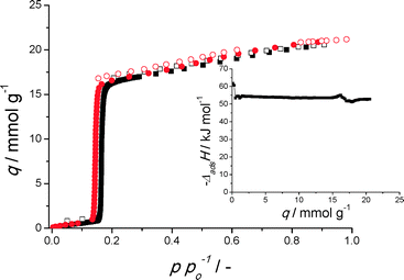 | ||
Fig. 1 Water adsorption isotherms of CAU-10-H obtained from microwave synthesis at 298 (■) and 288 K ( ). Closed symbols indicate adsorption, open symbols desorption. (inset) Isosteric enthalpy of adsorption (calculated with eqn (S1†)). ). Closed symbols indicate adsorption, open symbols desorption. (inset) Isosteric enthalpy of adsorption (calculated with eqn (S1†)). | ||
Formation of CAU-10-H on substrates
As metallic supports display higher thermal conductivity and are desired for the actual application, it was evident to employ aluminium supports with an (anodized) aluminium-oxide layer. The oxide layer is 15 μm thick in case of a-Al, whereas on metallic aluminium a native oxidic skin layer of only 4 nm is present.31 Furthermore, anodized oxide layers are composed of amorphous alumina, if not calcined thoroughly,32 which might further increase reactivity compared to γ-alumina. No XRD reflections were observed for the anodized layer itself (Fig. S5†), confirming the amorphous structure of the alumina. Because of the anodization, a-Al substrates display mesoporosity and have a small water adsorption capacity, features absent for m-Al (Fig. S6†).
Reducing the amount of hydrochloric acid added by 50% for m-Al (Fig. S9†) results in a slightly lower coverage. When the amount of HCl is doubled (Fig. S9†), coverage is greatly reduced and crystals apparently appear only along grooves, likely created by the preferential dissolution of Al3+ ions from local aluminium crystal boundaries in the metallic support, as was observed in a previous study.17 Using HCl for syntheses on a-Al is detrimental for the integrity of the support itself and leads to the formation of an amorphous phase (Fig. S10–S12†). The added isophthalic acid linker is thus more than sufficient to extract Al3+-ions from the support (a-Al), though HCl by-product formation and incomplete surface coverage are observed (Fig. S10, S12†). The utilization of additional acids thus is not necessary, having an adverse effect on the formation of MOF crystals (and will further not be used on a-Al substrates).
When the amount of DMF is significantly reduced (this has e.g. a positive effect on the crystallization of MIL-53(Al)–NH2 (ref. 33)) for syntheses on m-Al, no CAU-10-H is formed and instead a large amount of recrystallized isophthalic acid is found (Fig. S13–S15†). For a-Al, crystallization apparently becomes more homogeneous with decreasing amounts of DMF, though for all experiments large fractions of the crystals formed on the surface consist of by-product(s) (Fig. S14, S16†).
The reduction of temperature or prolongation of reaction time might yield more controlled crystal growth.34–37 Unfortunately, when synthesis is performed at a lower temperature (115 °C), no satisfactory crystal growth is achieved (Fig. S17†). Longer reaction times (at 135 °C) result in larger crystals on the surface (Fig. S18†), but coverage becomes more inhomogeneous and by-product formation is increased (Fig. S19†). Apparently, undesired Ostwald-ripening38 occurs, limiting the use of longer crystallization times.
In summary, using direct synthesis methods, it has been found nearly impossible to obtain coatings of improved quality by means of varying synthesis conditions. Therefore separating crystal nucleation and growth is concluded to be a more feasible strategy. To this end, the reactive and thermal seeding approaches, from Hu et al.21 and Guerrero et al.,22 respectively, are adopted here.
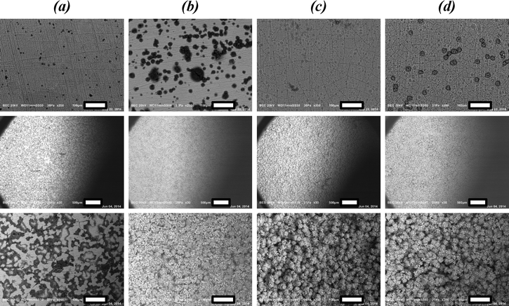
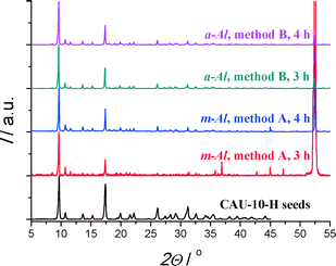
Remarkably, layers formed on anodized aluminium after 4 h of synthesis exhibit an excellent quality. A dense, homogeneous coverage of phase-pure CAU-10-H is created (Fig. 2d). The obtained quality is far better than that from syntheses performed in one step, indicating the potential of separating crystal nucleation and growth for the creation of MOF coatings on substrates.
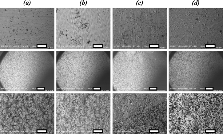
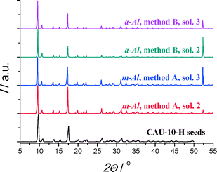
Compared to the coverage obtained with reactive seeding, the crystal size distribution seems slightly less homogeneous and there appear to be some areas with lower coverage. This might be attributed to the less intimate contact of seeds with the support in this method, than using reactive seeding. Nonetheless, also in this approach coverage, crystal homogeneity and phase purity are superior to those obtained via direct synthesis, once again underlining that separating crystal nucleation and growth is extremely suited for the creation of MOF coatings on substrates.
Comparison of coated substrates
These advancements have been achieved by proper substrate pretreatment, employment of anodized alumina on the surface layer, and the separation of crystal nucleation and growth. Especially, reactive seeding on pretreated a-Al has been shown to be a promising route, based on SEM microscopy and X-ray diffraction patterns. These techniques however, do not yield any information on adsorption capacity and (cyclic) stability, nor on the chemical composition of the coating. To elucidate this, further characterization has been performed for a selection of samples. Specifically, CAU-10-H obtained by direct synthesis (DS.) on untreated (UT.) a-Al and m-Al and on pretreated a-Al (method B, M.B.) and m-Al (method A, M.A.) are compared with the samples obtained by the reactive seeding (RS.) approach on both pretreated a-Al and m-Al.
IR spectra of CAU-10-H coated substrates after secondary synthesis (Fig. S40†) show similarity with the recorded spectrum for pure CAU-10-H (Fig. S39†), confirming once more the presence of CAU-10-H. However, there are notable differences as well, attributed primarily to the presence of by-product(s). Comparison of these IR spectra (Fig. S39, S40†) tends to indicate that the by-product contains Al–OH groups but hardly, if any, isophthalic acid (section S7†).
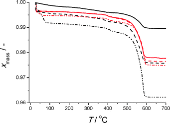
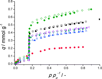
Thermo-gravimetric analysis (Fig. 6) is congruent with the qualitative indications by SEM analysis. The decrease in mass between 500 and 600 °C, which represents exothermic oxidation of the organic ligand, is largest for reactive seeding on a-Al. This is also observed in the SDTA profile (Fig. S41†). Notable exception is the profile for the direct synthesis on pretreated a-Al, for which seemingly significant amounts of isophthalic acid are present (section S7†). Water adsorption isotherms on the selected coated substrates are shown in Fig. 7.
Clearly, for all but direct synthesis on untreated a-Al, the desired step of CAU-10-H (Fig. 1) is mimicked on these substrates at the same relative pressure, demonstrating that coatings indeed behave like the bulk material. The a-Al substrate coated with CAU-10-H by reactive seeding shows the highest water adsorption capacity, displaying a significantly improved capacity compared to the other substrates and previous work.17 Nitrogen adsorption isotherms reveal strong diffusional limitations and henceforth do not offer a solid basis for detailed interpretation (Fig. S42†).
In the preceding conclusions regarding purity, surface coverage and crystal size distribution and adsorption capacity have been drawn. Ideally one would like to supplement this with a quantification of the amount of CAU-10-H present for selected samples. This desire is not so easily fulfilled, as e.g. methods based on quantitative elemental analysis cannot differentiate between aluminium present in the support and in the MOF structure. Hence further assumptions would be necessary, e.g. that all carbon atoms present in the sample belong to CAU-10-H on the substrate. As aluminium is predominantly present in the sample, because of the thickness of the dense support with respect to the porous coated layer, the uncertainty in the quantity of carbon present is anticipated to be large. Furthermore, weighing (dried) substrates before and after coating synthesis gives a skewed image as a-Al substrates are seemingly more prone to leaching and thus, for the same synthesis method, always display a lower weight of CAU-10-H (Table S1†). This method thus does not yield a clear indication on the amount of MOF present. Here, it is chosen to display trends in CAU-10-H based on two simple and rather unsophisticated methods, all with inherent drawbacks.
• First, one could estimate the amount of CAU-10-H on the substrate by the weight loss observed between 450 and 700 °C, assuming that all the loss observed (Fig. 6) is caused by burning the organic ligand and subsequently that all decomposed ligands were incorporated in the CAU-10-H structure.
• Second, by stating that the step in water adsorption (Fig. 7) is solely caused by CAU-10-H on the substrate surface and assuming that this has the same specific adsorption capacity as bulk MOF powder (Fig. 1), one can calculate the amount of MOF present on the substrate surface.
This intrinsically means however that substrates need to be cut to smaller proportions be able to fit a sample holder for water adsorption (~8 × 20 mm) or TGA analysis (~8 × 8 mm). This procedure might thus cause some loss of MOF material on the cutting edges and underestimate the actual loading. Nonetheless, estimated MOF loadings of these analyses are shown in Table 1, per unit of substrate surface.
| Synthesis method | Substrate | Loading/mg cm−2 | |
|---|---|---|---|
| TGA | H2O ads. | ||
| a Without HCl. b Method A. c Method B. d With pretreatment, seed reaction time 4 h. n.d. means not determinable. | |||
| Direct, no pretreatment | m-Al | 2.4 | 4.0 |
| a-Ala | 1.0 | n.d. | |
| Direct, with pretreatment | m-Alb | 2.6 | 2.8 |
| a-Alc | 2.8 | 3.6 | |
| Reactive seedingd | m-Alb | 2.8 | 3.3 |
| a-Alc | 4.4 | 5.0 | |
The MOF loadings determined by TGA and by water adsorption show similar trends and a fair agreement, although the quantity obtained by analysing TGA is always lower than for H2O adsorption. This could well be because of the necessity to cut these plates to manageable sizes. If this is the case, the loading indicated by H2O adsorption also underestimates the actual MOF loading, as the substrates have to be cut, but to lesser extent (vide supra). Nonetheless, based on water adsorption, a 25% increase in capacity has been achieved with reactive seeding on pretreated a-Al compared to the direct synthesis on untreated m-Al, the protocol used in previous work.17 This means that up to 48 kJ of heat can be withdrawn in the evaporator of an AHP/ADC per square meter of coated anodized aluminium surface (for metallic aluminium this is only 38 kJ (ref. 17)). On top of that, reactive seeding leads to a more homogenous coverage of crystals and a significantly narrower crystal size distribution as well as enhanced purity of CAU-10-H.
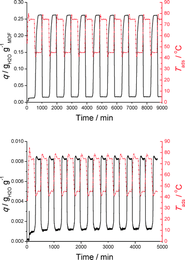
Clearly both bulk CAU-10-H and the substrate do not lose adsorption capacity over nine cycles. For the bulk powder this is expected as Fröhlich et al. already demonstrated that adsorption capacity of CAU-10-H is retained over 700 cycles.14 Clearly, stability is not compromised when this MOF is coated on a substrate, a feature indispensable for application in adsorption driven heat pumps and chillers. No loss of coated CAU-10(Al)-H was observed (in powder form) after these cyclic measurements, a first indication that these coatings are indeed mechanically robust enough to withstand cyclic ad- and desorption measurements. Furthermore, the response of the amount adsorbed on a temperature step change is significantly more rapid for the coated sample, indicating that heat and mass transport are enhanced when a coated substrate is employed, in comparison to the powder sample. The loading, however, expressed per unit mass of sample, is significantly lower for the substrate than for the bulk powder. This is because the aluminium substrate has a thickness of ~0.5 mm, and its coating has only a thickness in the order of 60–120 μm (SEM images), so most of the sample mass comes from the bulk aluminium. For application in AHP/ADC devices a thermodynamic optimization analysis of the coating thickness with respect to the support thickness should be performed, considering not only capacity, but also heat and mass transport.
The optimal coating method found for CAU-10-H on metallic aluminium substrates requires a number of necessary steps starting from metallic aluminium: (i) anodization, (ii) pretreatment, (iii) reactive seeding and (iv) secondary growth, which may hamper scalability of these coatings. In this sense, it might be beneficial to integrate some of the steps, especially merging anodization and pretreatment should be feasible. Additionally, the employed anodized layer was selected because of commercial availability, not because it necessarily holds optimal properties for MOF attachment. Optimizing anodization conditions and combining this step with the seeding step might thus further improve the manufacture of CAU-10-H coatings.
Conclusions
For manufacturing of CAU-10-H coatings on aluminium substrates, syntheses on metallic aluminium (m-Al) with varying manufacture conditions did not result in a notable improved coating quality. Any deviation from the standard synthesis protocol (SSP) leads to worse coatings.The porous amorphous aluminium oxide layer of anodized aluminium (a-Al) is more reactive and thus crystallization on the surface is easier. However, a significant amount of by-product(s) is formed, attributed to the higher content of extracted aluminium ions near the surface.
Substrate pretreatment improves both reproducibility and coating quality of CAU-10-H on both m-Al and a-Al substrates. For m-Al substrates cleaning with acetone (method A) yields optimal results. For a-Al, additionally the substrate should be contacted with a diluted HCl solution (6% in water) (method B) for optimal results. Despite the improvement achieved, obtained coatings are still suboptimal in coverage, homogeneity of crystal sizes and purity. Separation of crystal nucleation and growth yields significantly improved quality, showcased by the high purity and homogeneous crystal size distribution obtained by both thermal and reactive seeding on pretreated substrates. Especially reactive seeding in conjunction with pretreated a-Al (method B) yields full coverage of the substrate surface, a homogeneous layer thickness, narrow crystal size distribution, and high purity of the crystalline phase, fulfilling every requirement for application in adsorption driven heat pumps and chillers, namely: full coverage of the substrate surface, high MOF loading, homogeneous layer thickness, narrow crystal size distribution, sufficient stability and high purity of the crystalline phase. Coatings created with this method do not lose capacity upon repeated water adsorption–desorption cycles and respond much faster to temperature changes than bulk CAU-10-H powder.
Acknowledgements
Financial support from the Advanced Dutch Energy Materials (ADEM) program of the Dutch Ministry of Economic Affairs, Agriculture and Innovation is gratefully acknowledged.Notes and references
- M. F. De Lange, K. J. F. M. Verouden, T. J. H. Vlugt, J. Gascon and F. Kapteijn, Chem. Rev., 2015 Search PubMed , (Submitted).
- H. Reinsch, M. A. van der Veen, B. Gil, B. Marszalek, T. Verbiest, D. de Vos and N. Stock, Chem. Mater., 2012, 25, 17–26 CrossRef.
- R. J. Sheehan, Ullmann's Encyclopedia of Industrial Chemistry, Wiley-VCH Verlag GmbH & Co., 2000 Search PubMed.
- H. Kakiuchi, S. Shimooka, M. Iwade, K. Oshima, M. Yamazaki, S. Terada, H. Watanabe and T. Takewaki, Kagaku Kogaku Ronbunshu, 2005, 31, 361–364 CrossRef CAS.
- H. Kakiuchi, S. Shimooka, M. Iwade, K. Oshima, M. Yamazaki, S. Terada, H. Watanabe and T. Takewaki, Kagaku Kogaku Ronbunshu, 2005, 31, 273–277 CrossRef CAS.
- S. Shimooka, K. Oshima, H. Hidaka, T. Takewaki, H. Kakiuchi, A. Kodama, M. Kubota and H. Matsuda, J. Chem. Eng. Jpn., 2007, 40, 1330–1334 CrossRef.
- MITSUBISHI PLASTICS, Zeolitic Water Vapor Adsorbent: AQSOA, http://www.aaasaveenergy.com/products/001/pdf/AQSOA_1210E.pdf, Accessed 17–01, 2015.
- G. Liu, P. Tian, Y. Zhang, J. Li, L. Xu, S. Meng and Z. Liu, Microporous Mesoporous Mater., 2008, 114, 416–423 CrossRef CAS PubMed.
- Y. Xu, P. J. Maddox and J. W. Couves, J. Chem. Soc., Faraday Trans., 1990, 86, 425–429 RSC.
- A. M. Prakash and S. Unnikrishnan, J. Chem. Soc., Faraday Trans., 1994, 90, 2291–2296 RSC.
- R. D. Gougeon, E. B. Brouwer, P. R. Bodart, L. Delmotte, C. Marichal, J.-M. Chézeau and R. K. Harris, J. Phys. Chem. B, 2001, 105, 12249–12256 CrossRef CAS.
- F. Jiang, Z. Tang, J. Zhai, J. Ye and J. Han, Microporous Mesoporous Mater., 2006, 92, 129–133 CrossRef CAS PubMed.
- Y. Wan, C. D. Williams, C. V. Duke and J. J. Cox, J. Mater. Chem., 2000, 10, 2857–2862 RSC.
- D. Fröhlich, S. K. Henninger and C. Janiak, Dalton Trans., 2014, 43, 15300–15304 RSC.
- Y. K. Seo, J. W. Yoon, J. S. Lee, Y. K. Hwang, C. H. Jun, J. S. Chang, S. Wuttke, P. Bazin, A. Vimont and M. Daturi, Adv. Mater., 2012, 24, 806–810 CrossRef CAS PubMed.
- T. A. Nijhuis, A. E. Beers, T. Vergunst, I. Hoek, F. Kapteijn and J. A. Moulijn, Catal. Rev.: Sci. Eng., 2001, 43, 345–380 CAS.
- M. De Lange, C. Ottevanger, M. Wiegman, T. Vlugt, J. Gascon and F. Kapteijn, CrystEngComm, 2015, 17, 281–285 RSC.
- T. Ahnfeldt and N. Stock, CrystEngComm, 2012, 14, 505–511 RSC.
- S.-N. Kim, J. Kim, H.-Y. Kim, H.-Y. Cho and W.-S. Ahn, Catal. Today, 2013, 204, 85–93 CrossRef CAS PubMed.
- N. A. Khan, I. J. Kang, H. Y. Seok and S. H. Jhung, Chem. Eng. J., 2011, 166, 1152–1157 CrossRef CAS PubMed.
- Y. Hu, X. Dong, J. Nan, W. Jin, X. Ren, N. Xu and Y. M. Lee, Chem. Commun., 2010, 47, 737–739 RSC.
- V. V. Guerrero, Y. Yoo, M. C. McCarthy and H.-K. Jeong, J. Mater. Chem., 2010, 20, 3938–3943 RSC.
- M. Arnold, P. Kortunov, D. J. Jones, Y. Nedellec, J. Kärger and J. Caro, Eur. J. Inorg. Chem., 2007, 2007, 60–64 CrossRef PubMed.
- H. Bux, A. Feldhoff, J. Cravillon, M. Wiebcke, Y.-S. Li and J. Caro, Chem. Mater., 2011, 23, 2262–2269 CrossRef CAS.
- F. Schüth, K. S. W. Sing and J. Weitkamp, Handbook of porous solids, Wiley-VCH, 2002 Search PubMed.
- M. F. De Lange, T. J. H. Vlugt, J. Gascon and F. Kapteijn, Microporous Mesoporous Mater., 2014, 200, 199–215 CrossRef CAS PubMed.
- A. García Márquez, A. Demessence, A. E. Platero-Prats, D. Heurtaux, P. Horcajada, C. Serre, J.-S. Chang, G. Férey, V. A. de la Peña-O'Shea, C. Boissière, D. Grosso and C. Sanchez, Eur. J. Inorg. Chem., 2012, 2012, 5165–5174 CrossRef PubMed.
- H.-Y. Cho, D.-A. Yang, J. Kim, S.-Y. Jeong and W.-S. Ahn, Catal. Today, 2012, 185, 35–40 CrossRef CAS PubMed.
- H. Furukawa, F. Gándara, Y.-B. Zhang, J. Jiang, W. L. Queen, M. R. Hudson and O. M. Yaghi, J. Am. Chem. Soc., 2014, 136, 4369–4381 CrossRef CAS PubMed.
- J. Reboul, S. Furukawa, N. Horike, M. Tsotsalas, K. Hirai, H. Uehara, M. Kondo, N. Louvain, O. Sakata and S. Kitagawa, Nat. Mater., 2012, 11, 717–723 CrossRef CAS PubMed.
- T. Campbell, R. K. Kalia, A. Nakano, P. Vashishta, S. Ogata and S. Rodgers, Phys. Rev. Lett., 1999, 82, 4866–4869 CrossRef CAS.
- P. P. Mardilovich, A. N. Govyadinov, N. I. Mukhurov, A. M. Rzhevskii and R. Paterson, J. Membr. Sci., 1995, 98, 131–142 CrossRef CAS.
- E. Stavitski, M. Goesten, J. Juan-Alcañiz, A. Martinez-Joaristi, P. Serra-Crespo, A. V. Petukhov, J. Gascon and F. Kapteijn, Angew. Chem., Int. Ed., 2011, 50, 9624–9628 CrossRef CAS PubMed.
- E. Biemmi, S. Christian, N. Stock and T. Bein, Microporous Mesoporous Mater., 2009, 117, 111–117 CrossRef CAS PubMed.
- H. Reinsch and N. Stock, Microporous Mesoporous Mater., 2013, 171, 156–165 CrossRef CAS PubMed.
- Y.-B. Dong, Y.-Y. Jiang, J. Li, J.-P. Ma, F.-L. Liu, B. Tang, R.-Q. Huang and S. R. Batten, J. Am. Chem. Soc., 2007, 129, 4520–4521 CrossRef CAS PubMed.
- Y. X. Sun and W. Y. Sun, Chin. Chem. Lett., 2014, 25, 823–828 CrossRef CAS PubMed.
- J. W. Muller, Crystallization, Butterworth-Heinemann Ltd, Oxford, Revised edn., 2001, vol. 4 Search PubMed.
- H. Guo, G. Zhu, I. J. Hewitt and S. Qiu, J. Am. Chem. Soc., 2009, 131, 1646–1647 CrossRef CAS PubMed.
- R. Makiura, S. Motoyama, Y. Umemura, H. Yamanaka, O. Sakata and H. Kitagawa, Nat. Mater., 2010, 9, 565–571 CrossRef CAS PubMed.
- K. Yusenko, M. Meilikhov, D. Zacher, F. Wieland, C. Sternemann, X. Stammer, T. Ladnorg, C. Wöll and R. A. Fischer, CrystEngComm, 2010, 12, 2086–2090 RSC.
- F. Jeremias, D. Frohlich, C. Janiak and S. K. Henninger, RSC Adv., 2014, 4, 24073–24082 RSC.
- S. Hermes, D. Zacher, A. Baunemann, C. Wöll and R. A. Fischer, Chem. Mater., 2007, 19, 2168–2173 CrossRef CAS.
- I. Bezverkhyy, G. Ortiz, G. Chaplais, C. Marichal, G. Weber and J.-P. Bellat, Microporous Mesoporous Mater., 2014, 183, 156–161 CrossRef CAS PubMed.
- K. L. Nagy and A. C. Lasaga, Geochim. Cosmochim. Acta, 1992, 56, 3093–3111 CrossRef CAS.
- J. Y. Bottero, J. M. Cases, F. Fiessinger and J. E. Poirier, J. Phys. Chem., 1980, 84, 2933–2939 CrossRef CAS.
- A. Boumaza, L. Favaro, J. Lédion, G. Sattonnay, J. B. Brubach, P. Berthet, A. M. Huntz, P. Roy and R. Tétot, J. Solid State Chem., 2009, 182, 1171–1176 CrossRef CAS PubMed.
Footnote |
| † Electronic supplementary information (ESI) available: Characterization methods and additional characterization on powder samples, bare supports and coatings obtained using either direct synthesis, reactive or thermal seeding. See DOI: 10.1039/c5ce00789e |
| This journal is © The Royal Society of Chemistry 2015 |

