Halogen-bonded halide networks from chiral neutral spacers†
Julien
Lieffrig
,
Arnode G.
Niassy
,
Olivier
Jeannin
and
Marc
Fourmigué
*
Institut des Sciences Chimiques de Rennes, Université Rennes 1, CNRS UMR 6226, Campus de Beaulieu, 35042 Rennes, France. E-mail: marc.fourmigue@univ-rennes1.fr
First published on 14th October 2014
Abstract
Chiral, ditopic, halogen bond donor molecules are prepared from the reaction of C6F5I with three different enantiopure chiral diols, namely, (R,R)-2,3-butanediol, (R,R)-hydrobenzoin and S-binaphthol, with displacement of the fluorine atom para to the iodine atom in C6F5I, to give (R,R)-1, (R,R)-2 and (S)-3, respectively. Chiral, halogen-bonded networks with halide anions are investigated upon co-crystallisation of (R,R)-1 with (Et3S+, I−), (Et4N+, Br−), (n-Bu4N+, Br−) and (n-Pe4N+, Br−). In the first three salts with 1![[thin space (1/6-em)]](https://www.rsc.org/images/entities/char_2009.gif) :
:![[thin space (1/6-em)]](https://www.rsc.org/images/entities/char_2009.gif) 1 stoichiometry, the halide anions are coordinated by two iodine atoms with short I⋯X− (X− = I−, Br−) distances and acute (75–80°) I⋯X−⋯I angles, leading to the formation of chains, eventually organized into helices around twofold screw axes as in [(R,R)-1]·[Bu4NBr]. Co-crystallisation with tetrapentylammonium bromide affords a 2
1 stoichiometry, the halide anions are coordinated by two iodine atoms with short I⋯X− (X− = I−, Br−) distances and acute (75–80°) I⋯X−⋯I angles, leading to the formation of chains, eventually organized into helices around twofold screw axes as in [(R,R)-1]·[Bu4NBr]. Co-crystallisation with tetrapentylammonium bromide affords a 2![[thin space (1/6-em)]](https://www.rsc.org/images/entities/char_2009.gif) :
:![[thin space (1/6-em)]](https://www.rsc.org/images/entities/char_2009.gif) 1 stoichiometry salt, [(R,R)-1]2·[Pe4NBr], with a fourfold coordination around the Br− anion and the formation of a square lattice network built out of interconnected helices.
1 stoichiometry salt, [(R,R)-1]2·[Pe4NBr], with a fourfold coordination around the Br− anion and the formation of a square lattice network built out of interconnected helices.
Introduction
In the context of crystal engineering, the controlled formation of helical crystalline structures remains an attractive challenge as such structures play a crucial role in biological1 as well as organic or inorganic systems.2 Accordingly, different intermolecular interactions such as metal coordination, hydrogen bonding3 or π–π interactions4 have been used to generate such helical supramolecular assemblies. Besides, halogen bonding5–7 has also been recently established as a powerful intermolecular interaction8 for the elaboration of complex supramolecular architectures.9 Halogen bonding describes an attractive interaction between a Lewis base acting as a halogen bond acceptor and a polarizable covalently bound halogen atom acting as a halogen bond donor through the so-called σ-hole, which develops on the halogen atom, in the prolongation of the C–X bond. This interaction is thus essentially of electrostatic nature albeit charge-transfer contributions start to play a role in the strongest halogen bonds.10 For example, halide anions (Cl−, Br−, I−) act as very efficient halogen bond acceptors in solution11 as in the solid state.12 Many examples of extended anionic networks were reported incorporating neutral iodinated spacers as halogen bond donors,13 (Scheme 1) with two, three or four halogen atoms, such as diiodoacetylene or tetraiodoethylene.14,15 Tetrahedral CBr4 is known to form diamond-type structures.16 Many other ditopic and linear molecules were used, such as α,ω-diiodoperfluoroalkanes or 1,4-diiodoperfluorobenzene.17 Honeycomb lattices were isolated with tritopic spacers such as 1,3,5-triiodotrifluorobenzene,18 or an extended tris(iodoacetylene) analog;19 thus the possibility is opened for interpenetrated halide networks.20 Besides halide anions, one can also mention thiocyanate,21 perchlorate22 or halometallate anions.23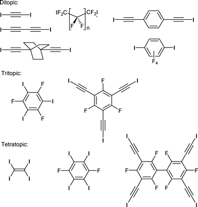 | ||
| Scheme 1 Examples of di-, tri-, and tetratopic neutral molecules acting as halogen bond donors toward halide anions. | ||
By comparison with other intermolecular interactions mentioned above, the use of halogen bonding as a crystal engineering tool in the formation of chiral, eventually helical structures has been only rarely mentioned. An earlier beautiful example is provided by the resolution of a racemic 1,2-dibromohexafluoropropane through its crystallization with (−)-sparteine hydrobromide into supramolecular helices stabilised by C–Br⋯Br− halogen bond interactions.24 Halogen bonds were also mentioned to favour the bundling of hydrogen-bonded chiral helices made out of halogen-substituted carboxylate salts of chiral amines.3b More recently, a chiral iodinated tetrathiafulvalene has been electro-crystallised in the presence of chloride or bromide anions to afford infinite halogen-bonded chains in the chiral C222 space group.25 In other reported examples of such networks built out of neutral di- or tetratopic halogen bond donors, the chirality or helical supramolecular organisation is most often derived from the presence of helices of opposite chirality organized around 21 screw axes,3,26 or from the spontaneous resolution of halogen-bonded systems into a conglomerate of both enantiomeric crystals,27 not only in 3D crystals but also on 2D monolayers grown on graphite.28 Note also the formation of a chiral nematic phase from halogen-bonded, bent-core achiral mesogen.29 In order to favour the formation of intrinsically chiral structures without relying only on serendipity, we decided to investigate neutral iodinated spacers with a built-in chirality, taking advantage of the availability of numerous chiral molecules in their enantiopure form. From this chiral pool, we selected appropriate precursors easily transformable into ditopic halogen bond donors and explored their ability to crystallise with halide anions as halogen bond acceptors toward the formation of helical halogen-bonded anionic chains.
Results and discussion
Neutral chiral spacers
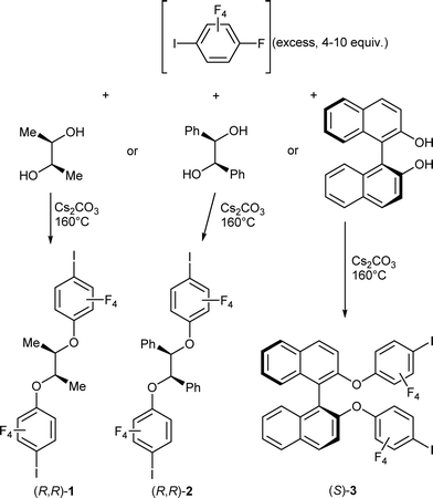
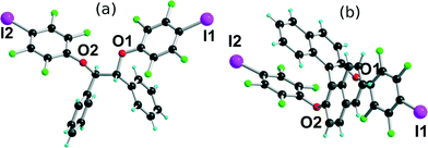
Our synthetic approach to the different chiral spacers described here is based on a reaction path described earlier for achiral diols.30,31 The SNAr between oxygen nucleophiles and iodopentafluorobenzene displaces the fluorine atom located para to the iodine atom, affording a variety of telechelic α,ω-di-(2,3,5,6-tetrafluoro-4-iodophenyl) derivatives. It was also demonstrated that despite the presence of a +M alkoxy substituent in the para position to iodine, these resulting derivatives were still effective as halogen bond donors toward neutral pyridine derivatives. We have accordingly expanded the scope of this reaction to three commercially available chiral enantiopure diols, namely, (R,R)-2,3-butanediol, (R,R)-hydrobenzoin and S-binaphthol, as described in Scheme 2. The reaction proceeds without solvent at high temperatures (160 °C), with Cs2CO3 as base, and provides the three enantiopure compounds in good to excellent yields (60–85%).Besides the usual characterization (see the Experimental section), the three neutral molecules were also investigated by single-crystal X-ray diffraction. Repeated recrystallizations of (R,R)-1 in different solvents did not afford any good-quality crystals. (R,R)-2 crystallises in the orthorhombic system, chiral space group P212121, with one molecule in the general position (Fig. 1a). The central CPh–C–C–CPh part adopts a gauche conformation, while the iodine atoms are not engaged in any specific intermolecular interactions. The binaphthol derivative (S)-3 crystallises in the orthorhombic system, space group P21ca, also with one molecule in the general position (Fig. 1b). Note also the almost face-to-face π–π interactions between the electron-deficient iodotetrafluorophenyl and the electron-rich naphthol rings. Such π–π interactions between aryl and fluoroaryl rings are well documented as a strongly stabilizing tool in crystal engineering.32,33 It should be stressed also here that in the two structures, the two iodine atoms are almost at opposite ends of the molecules, giving them a close-to-linear ditopic character.
Halogen-bonded halide salts
Halogen-bonded networks involving halide anions as XB acceptors were successfully isolated with the butanediol derivative (R,R)-1. Good-quality crystals were obtained with four different alkyl sulfonium and ammonium salts, namely, (Et3S+, I−), (Et4N+, Br−), (n-Bu4N+, Br−) and (n-Pe4N+, Br−), from the smallest triethylsulfonium to the largest tetrapentylammonium cation. They will be described successively, with specific attention to their halogen bond characteristics as well as their supramolecular organization.[(R,R)-1]·(Et3S+, I−) crystallises in the orthorhombic system, space group P22121, with the Et3S+ cation in the general position while two iodide anions and two (R,R)-1 molecules are located on twofold axes, hence the resulting 1![[thin space (1/6-em)]](https://www.rsc.org/images/entities/char_2009.gif) :
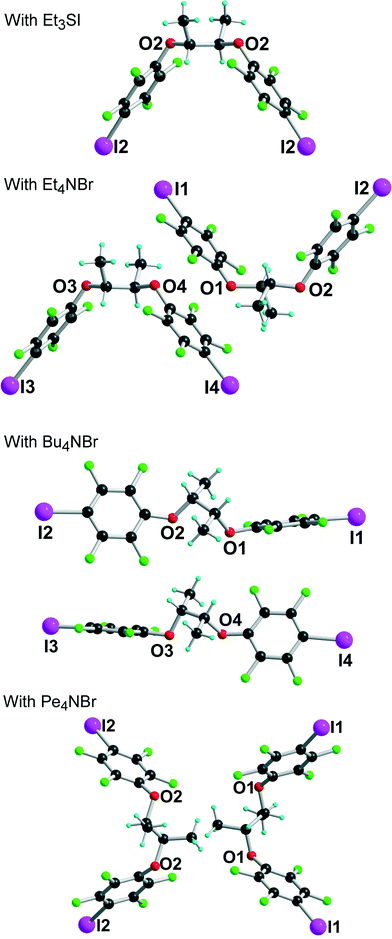
:![[thin space (1/6-em)]](https://www.rsc.org/images/entities/char_2009.gif) 1 stoichiometry. Considering the rotation along the central C–C bond, the two organic molecules each adopt an anti conformation, which gives them a V-shape (Fig. 2), while the pyramidal SEt3+ cation is disordered on two positions. The layered structure (Fig. 3) shows an alternation along c of cationic (SEt3+) and halogen-bonded [(R,R)-1]·I− anionic slabs. A projection view of one of these layers (Fig. 4) shows the very acute I⋯I−⋯I angles (74–76°) adopted by this structure. Such acute angles are not uncommon9–17,34 and are probably also stabilized by the existence of important dispersion forces between the iodine atoms coming into contact.
1 stoichiometry. Considering the rotation along the central C–C bond, the two organic molecules each adopt an anti conformation, which gives them a V-shape (Fig. 2), while the pyramidal SEt3+ cation is disordered on two positions. The layered structure (Fig. 3) shows an alternation along c of cationic (SEt3+) and halogen-bonded [(R,R)-1]·I− anionic slabs. A projection view of one of these layers (Fig. 4) shows the very acute I⋯I−⋯I angles (74–76°) adopted by this structure. Such acute angles are not uncommon9–17,34 and are probably also stabilized by the existence of important dispersion forces between the iodine atoms coming into contact.
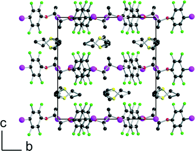 | ||
| Fig. 3 Projection view along the a axis of the unit cell of [(R,R)-1]·(Et3SI) showing the segregation between the disordered SEt3+ cations and the complex anionic layers. | ||
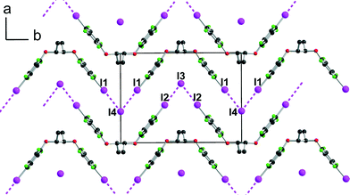 | ||
| Fig. 4 Projection view along c of one anionic layer in [(R,R)-1]·(Et3SI) showing the XB interactions between the iodine atoms I(1) and I(2) of [(R,R)-1] and the iodide anions I(3) and I(4). | ||
Geometrical characteristics of the I⋯I− halogen bonds collected in Table 1 confirm the important shortening when compared with the sum of van der Waals (I) and ionic (I−) radii, as well as the strong directionality of the interactions.
| Interaction | X | I⋯X− (Å) | Reduction parameter | C–I⋯X− (°) | I⋯X−⋯I (°) |
|---|---|---|---|---|---|
| [(R,R)-1]·Et3SI | |||||
| I(1)⋯I(4) | I | 3.484(1) | 0.862 | 178.2(2) | 75.59(1) |
| I(2)⋯I(3) | I | 3.475(1) | 0.860 | 173.1(2) | 74.43(1) |
| [(R,R)-1]·Et4NBr: | |||||
| I(1)⋯Br(1) | Br | 3.298(6) | 0.868 | 173.2(4) | 80.25(5) |
| I(2)⋯Br(1) | Br | 3.297(6) | 0.867 | 176.1(4) | |
| I(3)⋯Br(2) | Br | 3.266(6) | 0.859 | 177.6(4) | 79.73(5) |
| I(4)⋯Br(2) | Br | 3.250(6) | 0.855 | 179.4(4) | |
| [(R,R)-1]·Bu4NBr: | |||||
| I(1)⋯Br(1) | Br | 3.214(1) | 0.846 | 174.1(4) | 144.37(5) |
| I(2)⋯Br(1) | Br | 3.181(1) | 0.837 | 173.4(3) | |
| I(3)⋯Br(2) | Br | 3.273(2) | 0.861 | 175.4(3) | 150.24(5) |
| I(4)⋯Br(2) | Br | 3.232(2) | 0.850 | 172.7(3) | |
| [(R,R)-1]·Pe4NBr: | |||||
| I(1)⋯Br(1) | Br | 3.319(1) | 0.873 | 174.3(3) | 77.67(2), 120.80(2) |
| I(2)⋯Br(2) | Br | 3.301(1) | 0.869 | 175.5(3) | 78.08(2), 122.74(2) |
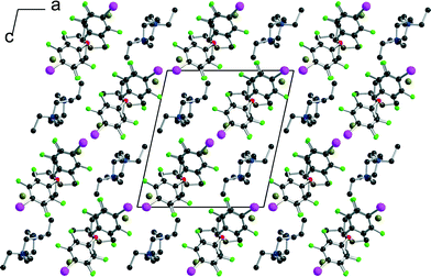
[(R,R)-1]·(Et4N+,Br−) crystallises in the monoclinic system, space group P21, with two crystallographically independent molecules (R,R)-1 and two crystallographically independent Et4NBr salts. A projection view of the unit cell along b (Fig. 5) again shows a segregation of halogen-bonded [(R,R)-1]·Br− anionic layers separated from each other along the (a + c) direction by the Et4N+ cation.
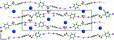
Within one anionic layer (Fig. 6) the neutral molecules adopt the anti conformation as above (see Fig. 2) and are linked to the Br− anion to form, by translation, halogen-bonded chains running along the b-axis with the same acute I⋯Br−⋯I angles. The two crystallographically independent chains are slightly different, with shorter and more linear interactions with the Br(2) anion (see Table 1).
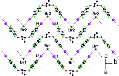 | ||
| Fig. 6 Projection view of one anionic layer in [(R,R)-1]·Et4NBr showing the XB interactions (pink dotted lines) with the bromide anions. | ||
The crystal structure of the 1![[thin space (1/6-em)]](https://www.rsc.org/images/entities/char_2009.gif) :
:![[thin space (1/6-em)]](https://www.rsc.org/images/entities/char_2009.gif) 1 adduct with Bu4NBr offers another structural organization, associated now with a gauche conformation (see Fig. 2) along the central C–C axis of [(R,R)-1]. Indeed, [(R,R)-1]·Bu4NBr crystallises in the orthorhombic system, space group P212121, again with two crystallographically independent molecules and two crystallographically independent Bu4NBr salts. The salt organizes into mixed layers incorporating the [(R,R)-1]·Br− halogen-bonded chains and the Bu4N+ cations (Fig. 7). The gauche conformation of the [(R,R)-1] molecule favours now an extended linear shape and results in a close to linear coordination around the Br− anions, with I⋯Br−⋯I angles of 144.37(5)° and 150.24(5)° around Br(1) and Br(2), respectively. The XB chains then develop along the twofold screw axis running along c, providing the first example within these series of a helical shape given to these chains from the combination of the neutral chiral iodinated molecules and the halogen bonding to the anions.
1 adduct with Bu4NBr offers another structural organization, associated now with a gauche conformation (see Fig. 2) along the central C–C axis of [(R,R)-1]. Indeed, [(R,R)-1]·Bu4NBr crystallises in the orthorhombic system, space group P212121, again with two crystallographically independent molecules and two crystallographically independent Bu4NBr salts. The salt organizes into mixed layers incorporating the [(R,R)-1]·Br− halogen-bonded chains and the Bu4N+ cations (Fig. 7). The gauche conformation of the [(R,R)-1] molecule favours now an extended linear shape and results in a close to linear coordination around the Br− anions, with I⋯Br−⋯I angles of 144.37(5)° and 150.24(5)° around Br(1) and Br(2), respectively. The XB chains then develop along the twofold screw axis running along c, providing the first example within these series of a helical shape given to these chains from the combination of the neutral chiral iodinated molecules and the halogen bonding to the anions.
Finally, the tetrapentylammonium bromide salt crystallises in the orthorhombic P222 space group with two crystallographically independent bromide anions and two crystallographically independent cations, all of them on 222 positions, while two crystallographically independent neutral XB donor molecules (R,R)-1 are located on a twofold axis, hence the formulation [(R,R)-1]2·[Pe4NBr], that is now two di-iodinated molecules (R,R)-1 for one bromide anion. The two (R,R)-1 molecules adopt an anti conformation with the now characteristic V shape (Fig. 2). As a consequence of this 2![[thin space (1/6-em)]](https://www.rsc.org/images/entities/char_2009.gif) :
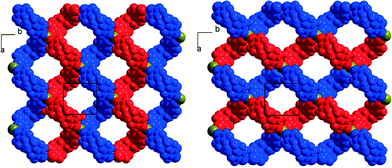
:![[thin space (1/6-em)]](https://www.rsc.org/images/entities/char_2009.gif) 1 stoichiometry, each anion is now surrounded by four iodine atoms, forming a distorted tetrahedron with I⋯Br−⋯I angles [around Br(1)] of 77.67(2)° and 120.80(2)° (see Table 1). The halogen-bonded network develops into layers alternating along the c axis. A projection view of one such layer (Fig. 8) shows a topological square lattice structure within the (a, b) plane. These layers can also be described as parallel sets of helices interconnected through the bromide anion by halogen bonding. As shown in Fig. 9, both “red” and “blue” helices running along a have the same left-handed (M) helicity, while those running along b have the same but right-handed (P) helicity. Note that the helicity observed here does not find its origin in the presence of a crystallographic 21 (or higher level) screw axis, but in the molecular chirality brought by the enantiopure iodinated linker.
1 stoichiometry, each anion is now surrounded by four iodine atoms, forming a distorted tetrahedron with I⋯Br−⋯I angles [around Br(1)] of 77.67(2)° and 120.80(2)° (see Table 1). The halogen-bonded network develops into layers alternating along the c axis. A projection view of one such layer (Fig. 8) shows a topological square lattice structure within the (a, b) plane. These layers can also be described as parallel sets of helices interconnected through the bromide anion by halogen bonding. As shown in Fig. 9, both “red” and “blue” helices running along a have the same left-handed (M) helicity, while those running along b have the same but right-handed (P) helicity. Note that the helicity observed here does not find its origin in the presence of a crystallographic 21 (or higher level) screw axis, but in the molecular chirality brought by the enantiopure iodinated linker.
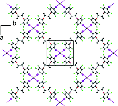 | ||
| Fig. 8 Projection view along c of one halogen-bonded plane in [(R,R)-1]2·[Pe4NBr]. The tetrapentylammonium cations and hydrogen atoms have been omitted for clarity. | ||
In conclusion, we have prepared original chiral, halogen bond donor, neutral molecules bearing two iodine atoms. Their conformational flexibility allows them, when co-crystallized with halide anions, to act as linear or bent bidentate spacers, allowing for the formation of chains with the Et3S+, Et4N+ and Bu4N+ cations, with the halide anion coordinated by two iodine atoms from two different molecules. In the tetrapentylammonium salt, a different stoichiometry with two linkers for one bromide anion leads to a fourfold coordination around the halide, which connects helical structures running along two perpendicular directions within layers. Such anionic polymeric networks, particularly those exhibiting supramolecular helical organisation, are now being investigated as a counter-ion in the electrocrystallization of π-type donor molecules such as tetrathiafulvalene derivatives,14b,c in order to favour the formation of chiral conducting salts,35 of current strong interest for the observation of rare magneto-chiral anisotropy effects.36
Experimental section
(1R,2R)-1,2-Dimethyl-1,2-bis(2,3,5,6-tetrafluoro-4-iodophenoxy)ethane
(R,R)-1. Pentafluoroiodobenzene (7.1 g, 24.1 mmol) is added to a mixture of (R,R)-2,3-butanediol (0.52 g, 5.8 mmol) and Cs2CO3 (3.6 g, 11.0 mmol), and the whole paste is heated without solvent under Ar at 160° for 20 h. After dilution with hexane and filtration on Celite®, the concentrated solution is purified by chromatography on silica gel with hexane as the eluent. Recrystallization from hexane afforded (R,R)-1 as white crystals (2.23 g). Yield: 61%. M.p. 116 °C. 1H NMR (CDCl3, TMS, ppm) δ: 1.43 (d, 3H, CH3), 4.60 (q, 1H, CH). 19F NMR (CDCl3, ppm) δ: −121.1, −153.4. 13C NMR (d6-DMSO, ppm) δ: 15.43, 67.91, 82.90, 135.99, 139.05, 142.34, 145.14, 148.30. Elem. anal. calcd. for C16H8F8I2O2: C, 30.12; H, 1.26%. Found: C, 30.25; H, 1.28%.(1R,2R)-1,2-Diphenyl-1,2-bis(2,3,5,6-tetrafluoro-4-iodophenoxy)ethane
(R,R)-2 is prepared as above from (R,R)-hydrobenzoin (0.51 g, 2.4 mmol), Cs2CO3 (1.54 g, 4.7 mmol) and C6F5I (3 mL, 22.4 mmol) and purified by chromatography on silica gel with CH2Cl2/hexane (1![[thin space (1/6-em)]](https://www.rsc.org/images/entities/char_2009.gif) :
:![[thin space (1/6-em)]](https://www.rsc.org/images/entities/char_2009.gif) 3) as the eluent. Recrystallization from hexane affords (R,R)-2 as white crystals (1.48 g). Yield: 82%. M.p. 118 °C. 1H NMR (CDCl3, TMS, ppm) δ: 5.61 (s, 2H, CH), 7.09–7.21 (m, 10H, Ar). 19F NMR (CDCl3, ppm) δ: −121.4, −152.2. 13C NMR (CDCl3, ppm) δ: 77.36, 88.84, 127.80, 128.53, 139.37, 134.75. Elem. anal. calcd. for C26H12F8I2O2: C, 40.97; H, 1.59%. Found: 41.24; H, 1.66%.
3) as the eluent. Recrystallization from hexane affords (R,R)-2 as white crystals (1.48 g). Yield: 82%. M.p. 118 °C. 1H NMR (CDCl3, TMS, ppm) δ: 5.61 (s, 2H, CH), 7.09–7.21 (m, 10H, Ar). 19F NMR (CDCl3, ppm) δ: −121.4, −152.2. 13C NMR (CDCl3, ppm) δ: 77.36, 88.84, 127.80, 128.53, 139.37, 134.75. Elem. anal. calcd. for C26H12F8I2O2: C, 40.97; H, 1.59%. Found: 41.24; H, 1.66%.
(S)-2,2′-Bis(2,3,5,6-tetrafluoro-4-iodophenoxy)-1,1′-binaphthyl
(S)-3 is prepared as above from S-binaphthol (0.3 g, 1.0 mmol), Cs2CO3 (0.70 g, 2.1 mmol) and pentafluoroiodobenzene (3.2 g, 10.9 mmol). Silica gel chromatography and recrystallization from hexane afforded (S)-3 as white crystals (0.55 g). Yield: 86%. M.p. 168 °C. 1H NMR (CDCl3, TMS, ppm) δ: 7.15 (d, 2H, Ar), 7.25–7.4 (m, 6H, Ar), 7.83 (d, 2H, Ar), 7.92 (d, 2H, Ar). 19F NMR (CDCl3, ppm) δ: −121.1, −150.9. 13C NMR (CDCl3, ppm) δ: 77.36, 117.65, 118.92, 125.29, 125.62, 127.34, 128.27, 130.55, 130.69, 133.44. Elem. anal. calcd. for C32H12F8I2O2: C; 46.07; H, 1.45. Found: C, 46.79; H, 1.67.X-ray diffraction studies
Colourless crystals of the four halide salts with (R,R)-1 were obtained as small rods by slow evaporation of mixed solutions, as detailed below. [(R,R)-1]·Et3SI: a solution of (R,R)-1 (10.8 mg, 16.9 μmol) in a 1![[thin space (1/6-em)]](https://www.rsc.org/images/entities/char_2009.gif) :
:![[thin space (1/6-em)]](https://www.rsc.org/images/entities/char_2009.gif) 1 CH2Cl2/hexane solution (1.5 mL) is mixed with a solution of Et3SI (4.4 mg , 17.9 μmol) in the same solvent mixture (1.5 mL). [(R,R)-1]·Et4NBr: as above with Et4NBr (7.0 mg, 22.8 μmol) in pure CH2Cl2. [(R,R)-1]·Bu4NBr: as above with (n-Bu)4NBr (7.0 mg, 21.7 μmol) in a 1
1 CH2Cl2/hexane solution (1.5 mL) is mixed with a solution of Et3SI (4.4 mg , 17.9 μmol) in the same solvent mixture (1.5 mL). [(R,R)-1]·Et4NBr: as above with Et4NBr (7.0 mg, 22.8 μmol) in pure CH2Cl2. [(R,R)-1]·Bu4NBr: as above with (n-Bu)4NBr (7.0 mg, 21.7 μmol) in a 1![[thin space (1/6-em)]](https://www.rsc.org/images/entities/char_2009.gif) :
:![[thin space (1/6-em)]](https://www.rsc.org/images/entities/char_2009.gif) 3 CH2Cl2/hexane solution. [(R,R)-1]2·Pe4NBr: as above with (n-Pe)4NBr (9.5 mg, 25 μmol) in hexane solution. When collected at low temperature, single crystals were taken in a loop in oil and put directly under a N2 stream at 150 K. Otherwise, they were glued at the end of a glass tip. Data were collected using a Bruker SMART II diffractometer with graphite-monochromated Mo-Kα radiation (λ = 0.71073 Å). Structures were solved by direct methods (SHELXS-97, SIR97)37 and refined (SHELXL-97) by full-matrix least-squares methods38 as implemented in the WinGX software package.39 Absorption corrections were applied. Hydrogen atoms were introduced at calculated positions (riding model), included in structure factor calculations, and not refined. Restraints were introduced for the refinement of the disordered Et3S+ cation in [(R,R)-1]·Et3SI as well as for the ends of the pentyl substituents in the Pe4N+ cation in [(R,R)-1]2·Pe4NBr. Crystallographic data are summarized in Table 2. The CIF files for each structure can be retrieved from the Cambridge Crystallographic Data Centre (CCDC) with deposition numbers CCDC 1025195–1025200 for (R,R)-2, (S)-3, [(R,R)-1]·Et3SI, [(R,R)-1]·Et4NBr, [(R,R)-1]·Bu4NBr and [(R,R)-1]2·Pe4NBr, respectively.
3 CH2Cl2/hexane solution. [(R,R)-1]2·Pe4NBr: as above with (n-Pe)4NBr (9.5 mg, 25 μmol) in hexane solution. When collected at low temperature, single crystals were taken in a loop in oil and put directly under a N2 stream at 150 K. Otherwise, they were glued at the end of a glass tip. Data were collected using a Bruker SMART II diffractometer with graphite-monochromated Mo-Kα radiation (λ = 0.71073 Å). Structures were solved by direct methods (SHELXS-97, SIR97)37 and refined (SHELXL-97) by full-matrix least-squares methods38 as implemented in the WinGX software package.39 Absorption corrections were applied. Hydrogen atoms were introduced at calculated positions (riding model), included in structure factor calculations, and not refined. Restraints were introduced for the refinement of the disordered Et3S+ cation in [(R,R)-1]·Et3SI as well as for the ends of the pentyl substituents in the Pe4N+ cation in [(R,R)-1]2·Pe4NBr. Crystallographic data are summarized in Table 2. The CIF files for each structure can be retrieved from the Cambridge Crystallographic Data Centre (CCDC) with deposition numbers CCDC 1025195–1025200 for (R,R)-2, (S)-3, [(R,R)-1]·Et3SI, [(R,R)-1]·Et4NBr, [(R,R)-1]·Bu4NBr and [(R,R)-1]2·Pe4NBr, respectively.
| Compound | (R,R)-2 | (S)-3 | [(R,R)-1]·Et3SI | [(R,R)-1]·Et4NBr | [(R,R)-1]·Bu4NBr | [(R,R)-1]2·Pe4NBr |
|---|---|---|---|---|---|---|
| Formula | C26H12F8I2O2 | C32H12F8I2O2 | C22H23F8I3O2S | C48H56Br2F16I4N2O4 | C32H44BrF8I2NO2 | C52H60BrF16I4NO4 |
| FW (g mol−1) | 762.16 | 834.22 | 884.16 | 1696.37 | 960.39 | 1654.51 |
| Crystal color | Colourless | Colourless | Colourless | Colourless | Colourless | Colourless |
| Crystal size (mm) | 0.87, 0.43, 0.38 | 0.26, 0.16, 0.03 | 0.31, 0.14, 0.12 | 0.40, 0.38, 0.23 | 0.42, 0.28, 0.17 | 0.27, 0.11, 0.01 |
| Crystal system | Orthorhombic | Orthorhombic | Orthorhombic | Monoclinic | Orthorhombic | Orthorhombic |
| Space group | P212121 | P21ca | P22121 | P21 | P212121 | P222 |
| T (K) | 293(2) | 293(2) | 150(2) | 293(2) | 150(2) | 150(2) |
| a (Å) | 8.0352(2) | 8.9564(3) | 11.5706(4) | 13.2765(2) | 12.0074(10) | 9.9519(3) |
| b (Å) | 16.1215(3) | 13.3787(4) | 15.5144(5) | 15.9187(2) | 15.2998(13) | 10.6977(3) |
| c (Å) | 20.0537(4) | 23.5539(7) | 16.0571(6) | 14.6917(2) | 41.115(3) | 30.4347(10) |
| α (°) | 90.00 | 90.00 | 90.00 | 90.00 | 90.00 | 90.00 |
| β (°) | 90.00 | 90.00 | 90.00 | 102.437(8) | 90.00 | 90.00 |
| γ (°) | 90.00 | 90.00 | 90.00 | 90.00 | 90.00 | 90.00 |
| V (Å3) | 2597.75(10) | 2822.35(15) | 2882.42(17) | 3032.15(7) | 7553.4(11) | 3240.15(17) |
| Z | 4 | 4 | 4 | 2 | 8 | 2 |
| D calc (g cm−3) | 1.949 | 1.963 | 2.037 | 1.858 | 1.689 | 1.696 |
| μ (mm−1) | 2.501 | 2.312 | 3.395 | 3.463 | 2.791 | 2.625 |
| Total refls. | 10![[thin space (1/6-em)]](https://www.rsc.org/images/entities/char_2009.gif) 107 107 |
25![[thin space (1/6-em)]](https://www.rsc.org/images/entities/char_2009.gif) 892 892 |
25![[thin space (1/6-em)]](https://www.rsc.org/images/entities/char_2009.gif) 659 659 |
58![[thin space (1/6-em)]](https://www.rsc.org/images/entities/char_2009.gif) 725 725 |
37![[thin space (1/6-em)]](https://www.rsc.org/images/entities/char_2009.gif) 334 334 |
14![[thin space (1/6-em)]](https://www.rsc.org/images/entities/char_2009.gif) 071 071 |
| Abs. corr. | Multi-scan | Multi-scan | Multi-scan | Multi-scan | Multi-scan | Multi-scan |
| T min, Tmax | 0.286, 0.387 | 0.648, 0.933 | 0.571, 0.665 | 0.273, 0.451 | 0.407, 0.622 | 0.714, 0.974 |
| Unique refls. | 5860 | 6435 | 6604 | 13![[thin space (1/6-em)]](https://www.rsc.org/images/entities/char_2009.gif) 706 706 |
17![[thin space (1/6-em)]](https://www.rsc.org/images/entities/char_2009.gif) 353 353 |
6357 |
| R int | 0.040 | 0.0602 | 0.0301 | 0.0370 | 0.0495 | 0.0265 |
| Unique refls. (I > 2σ(I)) | 5226 | 3973 | 5063 | 8986 | 14![[thin space (1/6-em)]](https://www.rsc.org/images/entities/char_2009.gif) 397 397 |
5040 |
| Refined parameter | 343 | 397 | 339 | 685 | 812 | 335 |
| R 1 (I > 2σ(I)) | 0.0475 | 0.0433 | 0.0518 | 0.0367 | 0.0823 | 0.0568 |
| wR2 (all data) | 0.1269 | 0.1089 | 0.1641 | 0.0888 | 0.1856 | 0.1711 |
| Flack parameter | 0.06(3) | 0.03(2) | 0.17(7) | 0.00(2) | 0.10(2) | 0.13(4) |
| Goodness of fit | 1.069 | 1.021 | 1.134 | 1.128 | 1.172 | 1.162 |
| Res. dens (e Å−3) | 1.131, −0.821 | 0.465, −0.653 | 0.937, −1.616 | 0.899, −0.979 | 1.508, −3.200 | 1.339, −1.240 |
Acknowledgements
We thank the CDIFX (Rennes) for access to the X-ray diffractometers.References
- (a) L. Pauling, R. B. Corey and H. R. Branson, Proc. Natl. Acad. Sci. U. S. A., 1951, 37, 205 CrossRef CAS; (b) J. D. Watson and F. H. C. Crick, Nature, 1953, 171, 737 CrossRef CAS; (c) A. Rich and F. H. C. Crick, Nature, 1955, 176, 915 CrossRef CAS; (d) K. P. Meurer and F. P. Vögtle, Top. Curr. Chem., 1985, 127, 1 CrossRef CAS.
- (a) I. Sato, R. Yamashima, K. Kadowaki, J. Yamamoto, T. Shibata and K. Soai, Angew. Chem., 2001, 113, 1130 CrossRef; (b) J. L. Zhou, Y. X. Wang, Y. Wang, Y. L. Song, H. G. Zheng, Y. Z. Li, L. P. Yang and X. Q. Xin, CrystEngComm, 2003, 5, 62 RSC; (c) M. Reggelin, S. Doerr, M. Klussmann, M. Schultz and M. Holbach, Proc. Natl. Acad. Sci. U. S. A., 2004, 101, 5461 CrossRef CAS PubMed.
- (a) S. Krishnaswamy, R. G. Gonnade, M. S. Shashidhar and M. M. Bhadbhade, CrystEngComm, 2010, 12, 4184 RSC; (b) T. Sasaki, I. Hisaki, S. Tsuzuki, N. Tohnaia and M. Miyata, CrystEngComm, 2012, 14, 5749 RSC.
- (a) V. K. Praveen, S. S. Babu, C. Vijayakumar, R. Varghese and A. Ajayaghosh, Bull. Chem. Soc. Jpn., 2008, 81, 1196 CrossRef CAS; (b) J.-C. Xiao, J.-L. Xu, S. Cui, H.-B. Liu, S. Wang and Y.-L. Li, Org. Lett., 2008, 10, 645 CrossRef CAS PubMed; (c) F. Dumitru, Y.-M. Legrand, A. V. Lee and M. Barboiu, Chem. Commun., 2009, 2667 RSC.
- For the IUPAC definition of halogen bond, see: G. R. Desiraju, P. Shing Ho, L. Kloo, A. C. Legon, R. Marquardt, P. Metrangolo, P. Politzer, G. Resnati and K. Rissanen, Pure Appl. Chem., 2013, 85, 1711 CrossRef CAS.
- (a) Halogen Bonding: Fundamentals and Applications, ed. P. Metrangolo and G. Resnati, Structure and Bonding Springer-Verlag, Berlin, 2008, vol. 126 Search PubMed; (b) G. Cavallo, P. Metrangolo, T. Pilati, G. Resnati, M. Sansotera and G. Terraneo, Chem. Soc. Rev., 2010, 39, 3772 RSC; (c) P. Politzer, J. S. Murray and T. Clark, Phys. Chem. Chem. Phys., 2010, 12, 7748 RSC.
- G. Cavallo, P. Metrangolo, T. Pilati, G. Resnati and G. Terraneo, Cryst. Growth Des., 2014, 14, 2697 CAS.
- W. T. Pennington, G. Resnati and M. S. Taylor, CrystEngComm, 2013, 15, 3057 RSC.
- (a) P. Metrangolo, T. Pilati, G. Terraneo, S. Biella and G. Resnati, CrystEngComm, 2009, 11, 1187 RSC; (b) G. Cavallo, P. Metrangolo, T. Pilati, G. Resnati, M. Sansotera and G. Terraneo, Chem. Soc. Rev., 2010, 39, 3772 RSC; (c) F. Meyer and P. Dubois, CrystEngComm, 2013, 15, 3058 RSC; (d) A. Mukherjee, S. Tothadi and G. R. Desiraju, Acc. Chem. Res., 2014, 47, 2514 CrossRef CAS PubMed.
- (a) R. Cabot and C. A. Hunter, Chem. Commun., 2009, 2005 RSC; (b) M. G. Sarwar, B. Dragisic, L. J. Salsberg, C. Gouliaras and M. S. Taylor, J. Am. Chem. Soc., 2010, 132, 1646 CrossRef CAS PubMed.
- (a) M. G. Chudzinski, C. A. McClary and M. S. Taylor, J. Am. Chem. Soc., 2011, 133, 10559 CrossRef CAS PubMed; (b) M. G. Sarwar, B. Dragisic, S. Sagoo and M. S. Taylor, Angew. Chem., Int. Ed., 2010, 49, 1674 CrossRef CAS PubMed.
- (a) G. Cavallo, P. Metrangolo, T. Pilati, G. Resnati, M. Sansotera and G. Terraneo, Chem. Soc. Rev., 2010, 39, 3772 RSC; (b) P. Metrangolo, T. Pilati, G. Terraneo, S. Biella and G. Resnati, CrystEngComm, 2009, 11, 1187 RSC.
- (a) R. Weiss, M. Rechinger, F. Hampel and A. Wolski, Angew. Chem., Int. Ed. Engl., 1995, 34, 441 CrossRef CAS; (b) M. Ghassemzadeh, K. Harms and K. Dehnicke, Chem. Ber., 1996, 129, 115 CrossRef CAS; (c) M. Ghassemzadeh, K. Harms and K. Dehnicke, Chem. Ber., 1996, 129, 259 CrossRef; (d) M. Ghassemzadeh, K. Harms and K. Dehnicke, Z. Naturforsch., B: J. Chem. Sci., 1997, 52, 772 CAS; (e) M. Ghassemzadeh, J. Magull, D. Fenske and K. Dehnicke, Z. Naturforsch., B: J. Chem. Sci., 1996, 51, 1579 CAS.
- (a) J. D. Dunitz, H. Gehrer and D. Britton, Acta Crystallogr., Sect. B, 1972, 28, 1989 CrossRef CAS; (b) H. M. Yamamoto, J.-I. Yamaura and R. Kato, J. Mater. Chem., 1998, 8, 15 RSC; (c) H. M. Yamamoto, Y. Kosaka, R. Maeda, J. Yamaura, A. Nakao, T. Nakamura and R. Kato, ACS Nano, 2008, 2, 143 CrossRef CAS PubMed; (d) C. Lemouchi, C. S. Vogelsberg, L. Zorina, S. Simonov, P. Batail, S. Brown and M. A. Garcia-Garibay, J. Am. Chem. Soc., 2011, 133, 13765 CrossRef.
- H. Bock and S. Holl, Z. Naturforsch., B: J. Chem. Sci., 2002, 57, 713 CAS.
- S. V. Lindeman, J. Hecht and J. K. Kochi, J. Am. Chem. Soc., 2003, 125, 11597 CrossRef CAS PubMed.
- (a) J. Grebe, G. Geiseler, K. Harms and K. Dehnicke, Z. Naturforsch., B: J. Chem. Sci., 1999, 54, 77 CAS; (b) A. Abate, S. Biella, G. Cavallo, F. Meyer, H. Neukirch, P. Metrangolo, T. Pilati, G. Resnati and G. Terraneo, J. Fluorine Chem., 2009, 130, 1171 CrossRef CAS PubMed.
- (a) S. Triguero, R. Llusar, V. Polo and M. Fourmigué, Cryst. Growth Des., 2008, 8, 2241 CrossRef CAS; (b) P. Metrangolo, F. Meyer, T. Pilati, G. Resnati and G. Terraneo, Chem. Commun., 2008, 1635 RSC.
- J. Lieffrig, O. Jeannin and M. Fourmigué, J. Am. Chem. Soc., 2013, 135, 6200 CrossRef CAS PubMed.
- J. Lieffrig, H. M. Yamamoto, T. Kusamoto, H. Cui, M. Fourmigué and R. Kato, Cryst. Growth Des., 2011, 11, 4267 CAS.
- (a) P. Cauliez, V. Polo, T. Roisnel, R. Llusar and M. Fourmigué, CrystEngComm, 2010, 12, 558 RSC; (b) S. V. Rosokha, C. L. Stern, A. Swartz and R. Stewart, Phys. Chem. Chem. Phys., 2014, 16, 12968 RSC.
- (a) A. Abate, J. Marti-Rujas, P. Metrangolo, T. Pilati, G. Resnati and G. Terraneo, Cryst. Growth Des., 2011, 11, 4220 CrossRef CAS; (b) K.-S. Shin, O. Jeannin, M. Brezgunova, S. Dahaoui, E. Aubert, E. Espinosa, P. Auban-Senzier, R. Świetlik, A. Frąckowiak and M. Fourmigué, Dalton Trans., 2014, 43, 5280 RSC.
- J. E. Ormond-Prout, P. Smart and L. Brammer, Cryst. Growth Des., 2012, 12, 205 CAS.
- A. Farina, S. V. Meille, M. T. Messina, P. Metrangolo, G. Resnati and G. Vecchio, Angew. Chem., Int. Ed., 1999, 38, 2433 CrossRef.
- J. Lieffrig, R. Le Pennec, O. Jeannin, P. Auban-Senzier and M. Fourmigué, CrystEngComm, 2013, 15, 4408 RSC.
- S. Muniappan, S. Lipstman and I. Goldberg, Chem. Commun., 2008, 1777 RSC.
- H. Neukirch, E. Guido, R. Liantonio, P. Metrangolo, T. Pilati and G. Resnati, Chem. Commun., 2005, 1534 RSC.
- R. Gutzler, O. Ivasenko, C. Fu, J. L. Brusso, F. Rosei and D. F. Perepichka, Chem. Commun., 2011, 47, 9453 RSC.
- C. Präsang, A. C. Whitwood and D. W. Bruce, Chem. Commun., 2008, 2137 RSC.
- C. Guardigli, R. Liantonio, M. L. Mele, P. Metrangolo, G. Resnati and T. Pilati, Supramol. Chem., 2003, 15, 177 CrossRef CAS.
- For other examples of this reaction, see also: (a) J. Xu, X. Liu, T. Lin, J. Huang and C. He, Macromolecules, 2005, 38, 3554 CrossRef CAS; (b) D. W. Bruce, P. Metrangolo, F. Meyer, T. Pilati, C. Präsang, G. Resnati, G. Terraneo, S. G. Wainwright and A. C. Whitwood, Chem. – Eur. J., 2010, 16, 9511 CrossRef CAS PubMed; (c) L.-Y. You, S.-G. Chen, X. Zhao, Y. Liu, W.-X. Lan, Y. Zhang, H.-J. Lu, C.-Y. Cao and Z.-T. Li, Angew. Chem., Int. Ed., 2012, 51, 1657 CrossRef CAS PubMed; (d) T. Caronna, R. Liantonio, T. A. Logothetis, P. Metrangolo, T. Pilati and G. Resnati, J. Am. Chem. Soc., 2004, 126, 4500 CrossRef CAS PubMed; (e) P. Metrangolo, F. Meyer, T. Pilati, D. M. Proserpio and G. Resnati, Chem. – Eur. J., 2007, 13, 5765 CrossRef CAS PubMed.
- A. Mori, in The Importance of pi- Interactions in Crystal Engineering: Frontiers in Crystal Engineering, ed. E. R. T. Tiekink and J. Zuckerman-Schpector, John Wileys & Sons, Ltd., 2012, ch. 7, pp. 163–185 Search PubMed.
- (a) C. R. Patrick and G. S. Grosser, Nature, 1960, 187, 1021 CrossRef CAS; (b) G. W. Coates, A. R. Dunn, L. M. Henling, D. A. Dougherty and R. H. Grubbs, Angew. Chem., Int. Ed. Engl., 1997, 36, 248 CrossRef CAS; (c) C. Dai, P. Nguyen, T. B. Marder, A. J. Scott, W. Clegg and C. Viney, Chem. Commun., 1999, 2493 RSC; (d) S. W. Watt, C. Dai, A. J. Scott, J. M. Burke, R. L. Thomas, J. C. Collings, C. Viney, W. Clegg and T. B. Marder, Angew. Chem., Int. Ed., 2004, 43, 3061 CrossRef CAS PubMed.
- (a) K. Raatikainen, G. Cavallo, P. Metrangolo, G. Resnati, K. Rissanen and G. Terraneo, Cryst. Growth Des., 2013, 13, 871 CrossRef CAS; (b) N. L. Kilah, M. D. Wise and P. D. Beer, Cryst. Growth Des., 2011, 11, 4565 CrossRef CAS.
- (a) F. Pop, P. Auban-Senzier, A. Frackowiak, K. Ptaszynski, I. Olejniczak, J. D. Wallis, E. Canadell and N. Avarvari, J. Am. Chem. Soc., 2013, 135, 17176 CrossRef CAS PubMed; (b) N. Avarvari and J. D. Wallis, J. Mater. Chem., 2009, 19, 4061 RSC; (c) C. Réthoré, N. Avarvari, E. Canadell, P. Auban-Senzier and M. Fourmigué, J. Am. Chem. Soc., 2005, 127, 5748 CrossRef PubMed; (d) S. Yang, F. Pop, C. Melan, A. C. Brooks, L. Martin, P. Horton, P. Auban-Senzier, G. L. J. A. Rikken, N. Avarvari and J. D. Wallis, CrystEngComm, 2014, 16, 3906 RSC.
- F. Pop, P. Auban-Senzier, E. Canadell, G. L. J. A. Rikken and N. Avarvari, Nat. Commun., 2014, 5, 3757 CrossRef PubMed.
- A. Altomare, M. C. Burla, M. Camalli, G. Cascarano, C. Giacovazzo, A. Guagliardi, A. G. G. Moliterni, G. Polidori and R. Spagna, J. Appl. Crystallogr., 1999, 32, 115 CrossRef CAS.
- SHELX97 - Programs for Crystal Structure Analysis (Release 97–2), G. M. Sheldrick, 1998 Search PubMed.
- L. J. Farrugia, J. Appl. Crystallogr., 1999, 32, 837 CrossRef CAS.
Footnote |
| † CCDC 1025195–1025200. For crystallographic data in CIF or other electronic format see DOI: 10.1039/c4ce01935k |
| This journal is © The Royal Society of Chemistry 2015 |

