Functionalization of robust Zr(IV)-based metal–organic framework films via a postsynthetic ligand exchange†
Honghan
Fei
a,
Sonja
Pullen
b,
Andreas
Wagner
b,
Sascha
Ott
*b and
Seth M.
Cohen
*a
aDepartment of Chemistry and Biochemistry, University of California, San Diego, La Jolla, CA, USA 92093. E-mail: scohen@ucsd.edu; Tel: +1-858-822-5596
bDepartment of Chemistry, Angstrom Laboratories, Uppsala University, Box 523, 751 20 Uppsala, Sweden. E-mail: sascha.ott@kemi.uu.se; Tel: +46-18-471 7340
First published on 23rd October 2014
Abstract
A facile and efficient fabrication approach for homogeneous, crack-free UiO-66 films with exceptionally high crystallinity and tunable thickness on a transparent and conductive glass substrate is reported. Two functionalized species, a catechol ligand and a Fe2 complex with structural resemblance to the active site of [FeFe] hydrogenase, were introduced into the MOF films via a postsynthetic exchange. Voltammetric studies show the [FeFe] complex in the thinner UiO-66 films (2–5 μm) can be reduced electrochemically.
Metal–organic frameworks (MOFs) are crystalline materials with exceptionally high surface area and porosity1 that have gathered extensive attention for applications in gas absorption,2,3 catalysis,4 and molecular separation/sensing.5,6 In recent years, many efforts were directed towards the growth of MOF films,7 which is important for utilizing MOF materials8 in functional electronic devices.9 Most of these technological applications require chemically “inert” MOFs that are robust under harsh chemical conditions.10 Except in some limited studies on MIL-53(Al)11 and MIL-101(Cr),12 functionalized robust MOFs have not been widely described in the realm of thin film MOF growth.7,13,14
Unlike zeolites and other porous materials, the organic components in MOFs allow for the introduction of a wide variety of functional groups through either direct synthesis15 or postsynthetic approaches.16 Compared with other functionalization methods, postsynthetic ligand exchange (PSE, also termed “SALE”, solvent-assisted ligand exchange) has been increasingly studied as a facile and efficient functionalization approach in robust MOFs.17,18 Compared with extensive studies on postsynthetic functionalization of bulk MOF materials, only a few examples of postsynthetic covalent modification (PSM) have been described on MOF thin films.19–22 Importantly, the synthetic conditions described for MOF films may preclude installation of different functionalities using a direct synthetic approach. For example, reports of using 2-amino-1,4-benzenedicarboxylic acid (NH2-bdc) posed difficulties in preparing a high-quality, amino-functionalized Cu-paddlewheel SURMOF (surface-mounted MOFs) film that had been readily obtained with naphthalenedicarboxylic acid.7,21
Herein, we report a facile and efficient method to fabricate robust Zr(IV)-based UiO-66 (UiO = University of Oslo) films with adjustable thickness on fluoride-doped tin oxide (FTO) glass substrates via solvothermal growth. The resultant uniform and crack-free films strongly adhere to the substrate and exhibit high stability comparable to bulk UiO-66. More importantly, this study is a rare example of PSE for the functionalization of MOF films. An open metal-binding functionality (catechol group) and a thermally labile Fe2 complex, reminiscent of the [FeFe] hydrogenase active site, were successfully incorporated into UiO-66 films.
UiO-66 films were solvothermally grown on an FTO substrate via a method similar to recently reported studies.23–25 FTO was chosen as a transparent and conducting glass substrate, and was pretreated with a 1 mM 1,4-benzenedicarboxylic acid (H2bdc) solution in DMF to generate a self-assembled monolayer (SAM) of carboxylic acid-terminated organic ligands. The H2bdc concentration for the pretreatment was found to be important for producing optimal films as higher concentrations (5–10 mM) led to thicker MOF films with weaker film adhesion to the substrate. The SAM-decorated FTO was introduced to a DMF solution containing ZrCl4, H2bdc, and benzoic acid with a molar ratio of 1![[thin space (1/6-em)]](https://www.rsc.org/images/entities/char_2009.gif) :
:![[thin space (1/6-em)]](https://www.rsc.org/images/entities/char_2009.gif) 1
1![[thin space (1/6-em)]](https://www.rsc.org/images/entities/char_2009.gif) :
:![[thin space (1/6-em)]](https://www.rsc.org/images/entities/char_2009.gif) 60, which was heated to 120 °C for 24 h. It was found that the film thickness could be decreased by lowering the concentration of H2bdc during synthesis (e.g. ratio of 1
60, which was heated to 120 °C for 24 h. It was found that the film thickness could be decreased by lowering the concentration of H2bdc during synthesis (e.g. ratio of 1![[thin space (1/6-em)]](https://www.rsc.org/images/entities/char_2009.gif) :
:![[thin space (1/6-em)]](https://www.rsc.org/images/entities/char_2009.gif) 0.6
0.6![[thin space (1/6-em)]](https://www.rsc.org/images/entities/char_2009.gif) :
:![[thin space (1/6-em)]](https://www.rsc.org/images/entities/char_2009.gif) 60). The large excess of benzoic acid as a modulator was found to be necessary to control crystal growth on FTO glass.
60). The large excess of benzoic acid as a modulator was found to be necessary to control crystal growth on FTO glass.
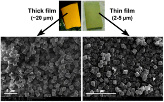
The MOF films are homogeneous and crack-free throughout the FTO glass substrate with sizes ranging from 0.5 to 2 cm2. The top-view field-emission scanning electron microscopy (FE-SEM) images showed the MOF films were stacked in compact arrays with crystalline particles over a long range, and exhibited monodisperse UiO-66 microcrystals with an octahedral morphology and particle size of ∼2 μm or ∼0.5 μm for thicker or thinner films, respectively (Fig. 1 and Fig. S1 and S2, ESI†). A cross-sectional SEM image indicates that the films consist of layers of MOF particles. The total thickness of the films obtained from a 1![[thin space (1/6-em)]](https://www.rsc.org/images/entities/char_2009.gif) :
:![[thin space (1/6-em)]](https://www.rsc.org/images/entities/char_2009.gif) 1 ratio of ZrCl4 and H2bdc were ∼20 μm. Thinner films made with less H2bdc were of a thickness of 2–5 μm and showed less uniform substrate coverage. The composition and crystallinity of the MOF films was further confirmed using powder X-ray diffraction (PXRD), indicating a phase-pure UiO-66 topology (Fig. 2 and 3, and Fig. S3, ESI†). Importantly, both the thicker and the thinner UiO-66 films were stable in water (including treatment with dilute HCl, pH = 3) and a variety of organic solvents (MeOH, CHCl3, CH3CN, etc.).
1 ratio of ZrCl4 and H2bdc were ∼20 μm. Thinner films made with less H2bdc were of a thickness of 2–5 μm and showed less uniform substrate coverage. The composition and crystallinity of the MOF films was further confirmed using powder X-ray diffraction (PXRD), indicating a phase-pure UiO-66 topology (Fig. 2 and 3, and Fig. S3, ESI†). Importantly, both the thicker and the thinner UiO-66 films were stable in water (including treatment with dilute HCl, pH = 3) and a variety of organic solvents (MeOH, CHCl3, CH3CN, etc.).
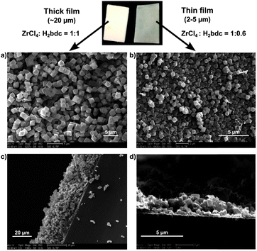 | ||
| Fig. 1 Film morphologies: top-view SEM image of (a) thicker (∼20 μm) and (b) thinner (∼2–5 μm) UiO-66 film. Cross-sectional SEM image of (c) thicker and (d) thinner films. | ||
Recently, PSE has been employed as an efficient tool to functionalize MOFs under mild conditions.26 The use of this methodology for MOF-films has however been highly limited to date. To the best of our knowledge, there is only one report of a MOF film (based on a more labile Zn-paddlewheel secondary building unit) to undergo PSE and, in this example, PSE was confined to the external surface of the film.20 Herein, we demonstrate that the UiO-66 films allow for the PSE with two different functional groups, which cannot be directly incorporated during solvothermal film growth.
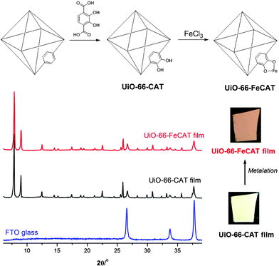
In an initial proof-of-concept study, a catechol ligand was introduced into the 20 μm UiO-66 film using PSE as an approach to incorporate open metal-chelating groups into MOF films (Fig. 2). PSE was carried out by carefully placing a UiO-66 film into a dilute, neutral (pH = 7) aqueous solution containing 2,3-dihydroxyl-1,4-benzenedicarboxylic acid (H2catbdc). Incubation for 24 h at room temperature was followed by washing of the film with water, water/ethanol (v/v = 1![[thin space (1/6-em)]](https://www.rsc.org/images/entities/char_2009.gif) :
:![[thin space (1/6-em)]](https://www.rsc.org/images/entities/char_2009.gif) 1), and ethanol. The resulting UiO-66-CAT film was uniform, off-white in colour, and strongly adhered to the substrate (Fig. 2). PXRD of the treated MOF film confirmed the high phase purity of UiO-66-CAT. Top-view SEM images showed no apparent change in microcrystalline particle size, but a slight decrease in crystallinity after PSE (Fig. S4, ESI†). The degree of H2catbdc functionalization in UiO-66-CAT film was ∼63% as determined by 1H NMR of HF/d6-DMSO digested films (Fig. S5, ESI†). The degree of functionality is thus significantly higher than that achieved with the bulk MOF (∼28%) under identical PSE conditions (room temperature for 24 h, see Table S1, ESI†).27
1), and ethanol. The resulting UiO-66-CAT film was uniform, off-white in colour, and strongly adhered to the substrate (Fig. 2). PXRD of the treated MOF film confirmed the high phase purity of UiO-66-CAT. Top-view SEM images showed no apparent change in microcrystalline particle size, but a slight decrease in crystallinity after PSE (Fig. S4, ESI†). The degree of H2catbdc functionalization in UiO-66-CAT film was ∼63% as determined by 1H NMR of HF/d6-DMSO digested films (Fig. S5, ESI†). The degree of functionality is thus significantly higher than that achieved with the bulk MOF (∼28%) under identical PSE conditions (room temperature for 24 h, see Table S1, ESI†).27
The highly robust UiO-66-CAT films with open metal-chelating sites allowed for efficient metalation to introduce an accessible metal centre into the MOF material. Treatment of UiO-66-CAT films with FeCl3 in aqueous solution results in films with a brown colour, indicative of the formation of the Fe-catecholato species. The film remains highly uniform, and both PXRD and SEM confirm the preservation of phase purity and identical particle morphology, respectively (Fig. 2, Fig. S6, ESI†). EDX indicated an atomic ratio of 1![[thin space (1/6-em)]](https://www.rsc.org/images/entities/char_2009.gif) :
:![[thin space (1/6-em)]](https://www.rsc.org/images/entities/char_2009.gif) 0.16 (Zr
0.16 (Zr![[thin space (1/6-em)]](https://www.rsc.org/images/entities/char_2009.gif) :
:![[thin space (1/6-em)]](https://www.rsc.org/images/entities/char_2009.gif) Fe), confirming that ∼26% of catechol sites were metalated with Fe (Fig. S7, ESI†).
Fe), confirming that ∼26% of catechol sites were metalated with Fe (Fig. S7, ESI†).
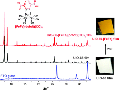
Having established a viable procedure for PSE in UiO-66 films on FTO, attempts were made to introduce a known proton reduction catalyst with structural features of the [FeFe] hydrogenase active site into films of different thicknesses. PSE was carried out by placing UiO-66 films in an aqueous solution of 20 mM [FeFe](dcbdt)(CO)6 (dcbdt = 2,3-dithiolato-1,4-benzene dicarboxylic acid, Fig. 3) at room temperature for 24–72 h, followed by extensive washing with MeOH, and drying in air.28 The treated MOF (UiO-66-[FeFe](dcbdt)(CO)6) films remain homogenous and crack-free, and exhibit particles with an identical size (∼2 μm or 0.5–1 μm) and shape as the UiO-66 films prior to PSE as evidenced by top-view SEM (Fig. 4).
The phase purity of the UiO-66-[FeFe](dcbdt)(CO)6 films was confirmed using PXRD, demonstrating a highly crystalline UiO-66 structure (Fig. 3, Fig. S3, ESI†). Diffuse reflectance UV-Vis spectroscopy of post-exchanged films confirmed the incorporation of [FeFe](dcbdt)(CO)6 with its characteristic absorption at 350 nm (Fig. S8, ESI†). The orange-yellow colour of the films after PSE is even visible to the eye (Fig. 3, Fig. S3, ESI†). The MOF particles could be liberated from the FTO substrate via sonication, which allowed for additional characterization of the material. The FTIR spectra of UiO-66-[FeFe](dcbdt)(CO)6 particles removed from FTO showed three bands at 2078 cm−1, 2038 cm−1, and 2001 cm−1, characteristic of the CO stretching of the [FeFe] complex (Fig. S9, ESI†). The degree of [FeFe] functionality was found to be between ∼32% and 35% for both film thicknesses, as evidenced by energy-dispersed X-ray spectroscopy (EDX) and/or C/H/N/S combustion analysis (Fig. S10 and Table S2, ESI†). Similar to H2catbdc, the incorporation of [FeFe](dcbdt)(CO)6 into the UiO-66 film is also increased when compared to previous studies on bulk UiO-66 (∼14% incorporation),28 which is likely due to an expanded liquid–solid interface. Generally, the procedures we have used when performing PSE on bulk UiO-66, the powdered solid is not stirred in order to reduce damage to the particles. The lack of stirring likely limits particle exposure to the solution; therefore, when formulated into the films described here, the particle–solution interface should be increased substantially. Particle size does not seem to contribute to the different rates of PSE, as MOF crystal sizes in the bulk (∼200 to 500 nm) are comparable to those in the thinner UiO-66 films used for PSE here.
Control experiments performed with [FeFe](bdt)(CO)6 (bdt = benzene-1,2-dithiolate), which has the same metal cluster, but lacks the coordinating carboxylates on the dithiolate ligand, support that incorporation of [FeFe](dcbdt)(CO)6 occurred via a PSE process. Exposing the UiO-66 film to identical PSE conditions using [FeFe](bdt)(CO)6 showed no substantial incorporation of [FeFe](bdt)(CO)6 after rinsing with MeOH. The lack of colour change of the film and the absence of CO bands in the FTIR spectrum (Fig. S9, ESI†) confirmed that this complex was not incorporated into the material. This negative control supports our contention that [FeFe](dcbdt)(CO)6 is incorporated into the UiO-66 films via a PSE process and not simply encapsulated within the MOF pores.
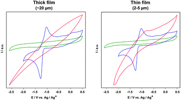
The electrochemical behaviour of UiO-66-[FeFe](dcbdt)(CO)6 was investigated using cyclic voltammetry (CV). In homogeneous DMF solution, Fe2(dcbdt)(CO)6 exhibits a quasi-reversible two-electron reduction at E1/2 = −1.18 V vs. Ag/Ag+ (E1/2 = (Epa − Epc)/2; Fig. 5), thus at a similar potential to that of previously reported Fe2(bdt)(CO)6.29 The relatively large difference between cathodic and anodic peak potentials in the CV of [FeFe](dcbdt)(CO)6 is not yet fully understood, but is presumably caused by processes that involve the COOH groups.
The UiO-66-[FeFe](dcbdt)(CO)6 films show a varying electrochemical response that depends on the thickness of the film (Fig. 5). CVs of thinner films (2–5 μm) show cathodic and anodic features at −1.45 V and −0.8 V, respectively, giving rise to a formal E1/2 = −1.13 V, which is very similar to that of [FeFe](dcbdt)(CO)6 in solution. The larger peak separation and peak broadening is not unexpected and is attributed to slow electron transfer kinetics. Importantly, neither blank FTO nor SAM-FTO electrodes when pre-treated under PSE conditions display any voltammetric features that could be assigned to the Fe2 complex (Fig. S11, ESI†). This clearly demonstrates that the observed reduction is a result of Fe2(dcbdt)(CO)6 that is incorporated into the MOF particles close to the electrode surface. CVs of thicker UiO-66-[FeFe](dcbdt)(CO)6 films show no detectable electrochemical response that could be assigned to the Fe2 complex, even though PSE has been evidenced in both films as described above. These electrochemical results suggest that only a negligible amount of Fe2(dcbdt)(CO)6 is present close to the FTO surface in the 20 μm films.
In conclusion, we have discovered a solvothermal growth of uniform, crack-free UiO-66 films with high crystallinity and robustness. The film thickness can be tuned by varying the ratio between ZrCl4 and H2bdc that is added during synthesis. Two distinct functional groups, which cannot be directly incorporated using conventional MOF film growth approaches, were incorporated into the film with high efficiency under mild reaction conditions. Electrochemical analysis showed that 20 μm thick UiO-66-[FeFe](dcbdt)(CO)6 films are not electrochemically active, but in thinner 2–5 μm films, the Fe2 complex shows a comparable electrochemical response as the free complex in solution. The strong adhesion of the MOF films and the robust nature of UiO-66 provide a versatile platform to synthesize a variety of functional, solid-state thin film materials.
This work was supported by grants from the National Science Foundation, Division of Materials Research (DMR-1262226, H.F., S.M.C.), the Swedish Research Council, Knut and Alice Wallenberg Foundation, and the Swedish Energy Agency (S.P., A.W., S.O.).
Notes and references
- M. O'Keeffe and O. M. Yaghi, Chem. Rev., 2012, 112, 675 CrossRef PubMed.
- K. Sumida, D. L. Rogow, J. A. Mason, T. M. McDonald, E. D. Bloch, Z. R. Herm, T.-H. Bae and J. R. Long, Chem. Rev., 2012, 112, 724 CrossRef CAS PubMed.
- M. P. Suh, K. S. Park, T. K. Prasad and D. Lim, Chem. Rev., 2012, 112, 782 CrossRef CAS PubMed.
- M. Yoon, R. Srirambalaji and K. Kim, Chem. Rev., 2012, 112, 1196 CrossRef CAS PubMed.
- L. E. Kreno, K. Leong, O. K. Farha, M. Allendorf, R. P. Van Duyne and J. T. Hupp, Chem. Rev., 2012, 112, 1105 CrossRef CAS PubMed.
- J.-R. Li, J. Sculley and H.-C. Zhou, Chem. Rev., 2012, 112, 869 CrossRef CAS PubMed.
- A. Betard and R. A. Fischer, Chem. Rev., 2012, 112, 1055 CrossRef CAS PubMed.
- P. Falcaro, R. Ricco, C. M. Doherty, K. Liang, A. J. Hill and M. J. Styles, Chem. Soc. Rev., 2014, 43, 5513 RSC.
- V. Stavila, A. A. Talin and M. D. Allendorf, Chem. Soc. Rev., 2014, 43, 5994 RSC.
- J. J. Low, A. I. Benin, P. Jakubczak, J. F. Abrahamian, S. A. Faheem and R. R. Willis, J. Am. Chem. Soc., 2009, 131, 15834 CrossRef CAS PubMed.
- Y. Hu, X. Dong, J. Nan, W. Jin, X. Ren, N. Xu and Y. M. Lee, Chem. Commun., 2010, 47, 737 RSC.
- A. Demessence, P. Horcajada, C. Serre, C. Boissiere, D. Grosso, C. Sanchez and G. Ferey, Chem. Commun., 2009, 7149 RSC.
- D. Zacher, O. Shekhah, C. Woll and R. A. Fischer, Chem. Soc. Rev., 2009, 38, 1418 RSC.
- O. Shekhah, J. Liu, R. A. Fischer and C. Woll, Chem. Soc. Rev., 2011, 40, 1081 RSC.
- H. Deng, C. J. Doonan, H. Furukawa, R. B. Ferreira, J. Towne, C. B. Knobler, B. Wang and O. M. Yaghi, Science, 2010, 327, 846 CrossRef CAS PubMed.
- S. M. Cohen, Chem. Rev., 2012, 112, 970 CrossRef CAS PubMed.
- P. Deria, J. E. Mondloch, O. Karagiaridi, W. Bury, J. T. Hupp and O. K. Farha, Chem. Soc. Rev., 2014, 43, 5896 RSC.
- C. K. Brozek and M. Dinca, Chem. Soc. Rev., 2014, 43, 5456 RSC.
- T. Gadzikwa, G. Lu, C. L. Stern, S. R. Wilson, J. T. Hupp and S. T. Nguyen, Chem. Commun., 2008, 5493 RSC.
- M. Kondo, S. Furakawa, K. Hirai and S. Kitagawa, Angew. Chem., Int. Ed., 2010, 49, 5327 CrossRef CAS PubMed.
- B. Liu, M. Ma, D. Zacher, A. Betard, K. Yusenko, N. Metzler-Nolte, C. Woll and R. A. Fischer, J. Am. Chem. Soc., 2011, 133, 1734 CrossRef CAS PubMed.
- Z. Wang, J. Liu, H. K. Arslan, S. Grosjean, T. Hagendorn, H. Gliemann, S. Brase and C. Woll, Langmuir, 2013, 29, 15958 CrossRef CAS PubMed.
- C. R. Wade, M. Li and M. Dinca, Angew. Chem., Int. Ed., 2013, 125, 13619 CrossRef.
- C.-W. Kung, T. C. Wang, J. E. Mondloch, D. Fairen-Jimenez, D. M. Gardner, W. Bury, J. M. Klingsporn, J. C. Barnes, R. Van Duyne, J. F. Stoddard, M. R. Wasielewski, O. K. Farha and J. T. Hupp, Chem. Mater., 2013, 25, 5012 CrossRef CAS.
- W. A. Maza, S. R. Ahrenholtz, C. C. Epley, C. S. Day and A. J. Morris, J. Phys. Chem. C, 2014, 118, 14200 CAS.
- O. Karagiaridi, W. Bury, J. E. Mondloch, J. T. Hupp and O. K. Farha, Angew. Chem., Int. Ed., 2014, 53, 4530 CrossRef CAS PubMed.
- H. Fei, J. Shin, Y. S. Meng, M. Adelhardt, J. Sutter, K. Meyer and S. M. Cohen, J. Am. Chem. Soc., 2014, 136, 4965 CrossRef CAS PubMed.
- S. Pullen, H. Fei, A. Orthaber, S. M. Cohen and S. Ott, J. Am. Chem. Soc., 2013, 135, 16997 CrossRef CAS PubMed.
- D. Streich, M. Karnahl, Y. Astuti, C. W. Cady, L. Hammarström, R. Lomoth and S. Ott, Eur. J. Inorg. Chem., 2011, 1106 CrossRef CAS.
Footnote |
| † Electronic supplementary information (ESI) available: Experimental details and additional characterization of MOF films. See DOI: 10.1039/c4cc08218d |
| This journal is © The Royal Society of Chemistry 2015 |

